

3D Shapes
workaround without |
|
the same result with |
||||||
status code 2: |
|
|
status code 2: |
|||||
ROTY -90 |
|
|
|
ROTY -90 |
|
|||
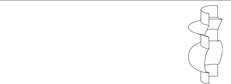
REVOLVE 26, 180, 16+32, |
REVOLVE 18, 180, 48, |
|||||||
7, |
1, 0, |
1, |
1, |
|
7, |
1, |
0, |
|
6.0001, |
|
6, |
1, |
2, |
2, |
|||
6, |
1, 0, |
1.0002, |
1, |
5.5, |
2, |
|||
5.9999, |
5, |
1, |
2, |
|
||||
5.5001, |
1.9998, |
1, |
4, |
1, |
2, |
|
||
5.5, |
2, |
0, |
|
1, |
3+COS(15), |
1+SIN(15), |
1, |
|
5.4999, |
1.9998, |
3+COS(30), |
1+SIN(30), |
1, |
||||
5.0001, |
1.0002, |
1, |
3+COS(45), |
1+SIN(45), |
1, |
|||
5, |
1, 0, |
1, |
1, |
|
3+COS(60), |
1+SIN(60), |
1, |
|
4.9999, |
|
3+COS(75), |
1+SIN(75), |
1, |
||||
4.0001, |
1, |
1, |
|
3, |
2, |
1, |
1+SIN(105), |
1, |
|
4, |
1, 0, |
|
1+SIN(15), |
1, |
3+COS(105), |
||||
3+COS(15), |
3+COS(120), |
1+SIN(120), |
1, |
||||||
3+COS(30), |
1+SIN(30), |
1, |
3+COS(135), |
1+SIN(135), |
1, |
||||
3+COS(45), |
1+SIN(45), |
1, |
3+COS(150), |
1+SIN(150), |
1, |
||||
3+COS(60), |
1+SIN(60), |
1, |
3+COS(165), |
1+SIN(165), |
1, |
||||
3+COS(75), 1+SIN(75), 1, |
2, |
1, |
2, |
|
|
||||
3, |
2, 1, |
|
1+SIN(105), |
1, |
1, |
0 |
|
|
|
3+COS(105), |
1, |
|
|
|
|
||||
3+COS(120), |
1+SIN(120), |
1, |
|
|
|
|
|||
3+COS(135), |
1+SIN(135), |
1, |
|
|
|
|
|||
3+COS(150), |
1+SIN(150), |
1, |
|
|
|
|
|||
3+COS(165), |
1+SIN(165), |
1, |
|
|
|
|
|||
2, |
1, 0, |
1, |
0, |
|
|
|
|
|
|
1.9999, |
|
|
|
|
|
|
|||
1, |
1, 0 |
|
|
|
|
|
|
|
|
RULED
RULED n, mask,
u1, v1, s1, ... un, vn, sn, x1, y1, z1, ... xn, yn, zn
72 |
ArchiCAD 11 GDL Reference Guide |
3D Shapes
RULED{2}
RULED{2} n, mask,
u1, v1, s1, ... un, vn, sn, x1, y1, z1, ... xn, yn, zn
RULED is a surface based on a planar curve and a space curve having the same number of nodes. Straight segments connect the corresponding nodes of the two polylines.
This is the only GDL element allowing the neighboring nodes to overlap.
The second version, RULED {2}, checks the direction (clockwise or counterclockwise) in which the points of both the top polygon and base polygon were defined, and reverses the direction if necessary. (The original RULED command takes only the base polygon into account, which can lead to errors.)
n: number of polyline nodes in each curve.
mask: controls the existence of the bottom, top and side polygon and the visibility of the edges on the generator polylines. The side polygon connects the first and last nodes of the curves, if any of them are not closed.
ui, vi: coordinates of the planar curve nodes. si: status of the lateral edges.
xi, yi, zi: coordinates of the space curve nodes.
Parameter restriction: n > 1
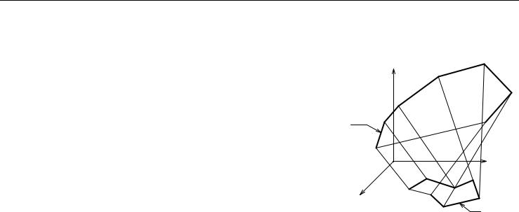
Masking:
mask = j1 + 2*j2 + 4*j3 + 16*j5 + 32*j6 + 64*j7 where j1, j2, j3, j5, j6, j7 can be 0 or 1.
j1 (1): base surface is present.
j2 (2): top surface is present (not effective if the top surface is not planar). j3 (4): side surface is present (a planar quadrangle or two triangles).
j5 (16): edges on the planar curve are visible.
j6 (32): edges on the space curve are visible.
j7 (64): edges on the surface are visible, surface is not smooth.
Status values:
0:lateral edges starting from the node are all visible.
1:lateral edges starting from the node are used for showing the contour.
Z
2
|
|
j2 |
|
j6 |
|
|
1 |
|
|
|
|
|
n |
j3 |
|
|
|
|
|
|
|
|
Y |
|
|
n |
j1 |
X |
|
1 |
|
|
|
||
|
|
2 |
j5 |
|
|
|
ArchiCAD 11 GDL Reference Guide |
73 |
3D Shapes
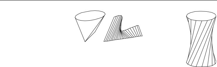
Examples:
R=3
RULED 16, 1+2+4+16+32, COS(22.5)*R, SIN(22.5)*R, 0, COS(45)*R, SIN(45)*R, 0, COS(67.5)*R, SIN(67.5)*R, 0, COS(90)*R, SIN(90)*R, 0,
COS(112.5)*R, SIN(112.5)*R, 0, COS(135)*R, SIN(135)*R, 0, COS(157.5)*R, SIN(157.5)*R, 0, COS(180)*R, SIN(180)*R, 0, COS(202.5)*R, SIN(202.5)*R, 0, COS(225)*R, SIN(225)*R, 0, COS(247.5)*R, SIN(247.5)*R, 0, COS(270)*R, SIN(270)*R, 0, COS(292.5)*R, SIN(292.5)*R, 0, COS(315)*R, SIN(315)*R, 0, COS(337.5)*R, SIN(337.5)*R, 0, COS(360)*R, SIN(360)*R, 0, COS(112.5)*R, SIN(112.5)*R, 1, COS(135)*R, SIN(135)*R, 1, COS(157.5)*R, SIN(157.5)*R, 1, COS(180)*R, SIN(180)*R, 1, COS(202.5)*R, SIN(202.5)*R, 1, COS(225)*R, SIN(225)*R, 1, COS(247.5)*R, SIN(247.5)*R, 1, COS(270)*R, SIN(270)*R, 1, COS(292.5)*R, SIN(292.5)*R, 1, COS(315)*R, SIN(315)*R, 1, COS(337.5)*R, SIN(337.5)*R, 1, COS(360)*R, SIN(360)*R, 1, COS(22.5)*R, SIN(22.5)*R, 1, COS(45)*R, SIN(45)*R, 1, COS(67.5)*R, SIN(67.5)*R, 1, COS(90)*R, SIN(90)*R, 1
74 |
ArchiCAD 11 GDL Reference Guide |

3D Shapes
SWEEP
SWEEP n, m, alpha, scale, mask, u1, v1, s1, ... un, vn, sn, x1, y1, z1, ... xm, ym, zm
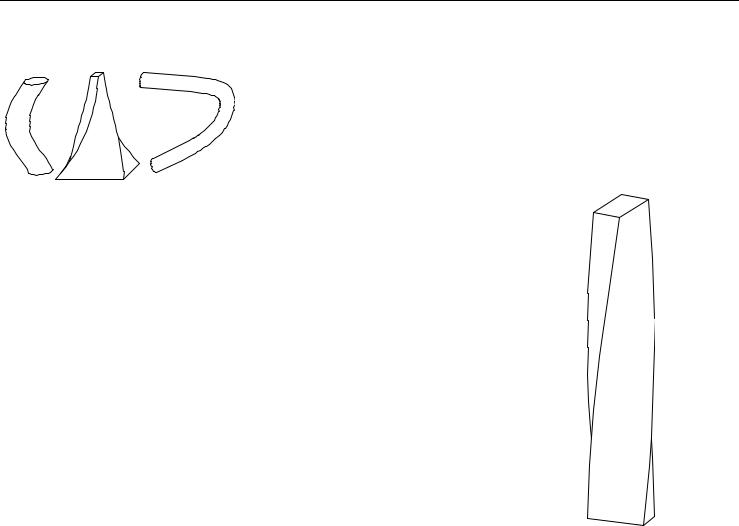
Surface generated by a polyline sweeping along a polyline space curve path.
The plane of the polyline follows the path curve. The space curve has to start from the x-y plane. If this condition is not met, it is moved along the z axis to start on the x-y plane.
The cross-section at point (xi, yi, zi) is perpendicular to the space curve segment between points (xi-1, yi-1, zi-1) and (xi, yi, zi). SWEEP can be used to model the spout of a teapot and other complex shapes.
n: number of polyline nodes. m: number of path nodes.
alpha: incremental polyline rotation on its own plane, from one path node to the next one. scale: incremental polyline scale factor, from one path node to the next one.
mask: controls the existence of the bottom and top polygons’ surfaces and edges. ui, vi: coordinates of the base polyline nodes.
si: status of the lateral edges.
xi, yi, zi: coordinates of the path curve nodes.
Parameter restrictions:
n |
> 1 |
|
m |
> |
1 |
z1 |
< |
z2 |
ArchiCAD 11 GDL Reference Guide |
75 |

3D Shapes
Masking:
mask = j1 + 2*j2 + 4*j3 + 16*j5 + 32*j6 + 64*j7 where j1, j2, j3, j5, j6, j7 can be 0 or 1.
j1 (1): base surface is present.
j2 (2): top surface is present.
j3 (4): side surface is present.
j5 (16): base edges are visible.
j6 (32): top edges are visible.
j7 (64): cross-section edges are visible, surface is articulated.
Status values:
0:lateral edges starting from the node are all visible.
1:lateral edges starting from the node are used for showing the contour.
|
Z |
|
|
|
|
|
|
|
j2 |
|
|
|
|
j6 |
|
|
|
|
m |
|
|
|
2 |
|
|
|
|
|
Y |
|
|
j3 |
|
|
|
n |
1 |
|
j1 |
|
|
|
||
X |
|
1 |
|
|
|
|
|
||
|
|
|
2 |
j5 |
|
|
|
|
76 |
ArchiCAD 11 GDL Reference Guide |
3D Shapes
Additional status codes allow you to create segments and arcs in the planar polyline using special constraints.
See “Additional Status Codes” on page 141 for details. Examples:
SWEEP 4, 12, 7.5, 1, 1+2+4+16+32,
-0.5, |
-0.25, 0, |
||
0.5, -0.25, 0, |
|||
0.5, |
0.25, |
0, |
|
-0.5, |
0.25, 0, |
||
0, |
0, |
0.5, |
|
0, |
0, |
1, |
|
0, |
0, |
1.5, |
|
0, |
0, |
2, |
|
0, |
0, |
2.5, |
|
0, |
0, |
3, |
|
0, |
0, |
3.5, |
|
0, |
0, |
4, |
|
0, |
0, |
4.5, |
|
0, |
0, |
5, |
|
0, |
0, |
5.5, |
|
0, |
0, |
6 |
|
ArchiCAD 11 GDL Reference Guide |
77 |