

6.8. Instrument Transformers
Instruments transformers are made for use with control devices and measuring instruments to extend their range and for isolation of these devices and instruments from high-voltage current-carrying parts. They are of two kinds, namely, voltage (potential) transformers and current transformers.
Voltage transformers do not differ in design from ordinary low-power transformers. The primary (HV) winding of such a transformer is connected to two line wires of the circuit the voltage of which is to be measured or controlled, while the secondary (LV) winding is connected to a voltmeter, or to the parallel coil of a wattmeter, watthour meter, etc. The turn ratio of a voltage transformer is chosen such that the secondary voltage is equal to 100 V at the rated primary voltage.
The operation of this transformer is similar to
the no-load operation of an ordinary transformer because the
resistance of a voltmeter or the resistance of the parallel coil
of a wattmeter or a watt-hour meter is high and the current in the
secondary can he neglected. It is u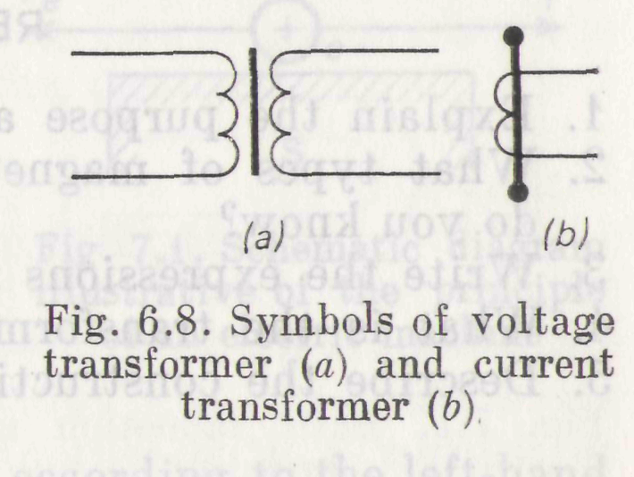 ndesirable
to connect many meters to the secondary. If we connect one more
voltmeter in parallel with the voltmeter placed across the secondary
or connect the parallel coil of a wattmeter or a watthour meter, the
current in the secondary will grow and the subsequent voltage
drop across the secondary terminals will decrease the accuracy
of readings of the meters.
ndesirable
to connect many meters to the secondary. If we connect one more
voltmeter in parallel with the voltmeter placed across the secondary
or connect the parallel coil of a wattmeter or a watthour meter, the
current in the secondary will grow and the subsequent voltage
drop across the secondary terminals will decrease the accuracy
of readings of the meters.
Current transformers serve to convert a high current in the primary to a low secondary current such that its value is equal to 5 A. The primary is placed in series with the metered circuit, namely, at the break of the line wire the current of which is to be measured, while the secondary is connected in series with an ammeter or with the series coil of a wattmeter or a watthour meter, i.e. with a meter of low impedance.
The operation of a current transformer differs substantially from that of an ordinary transformer. In the latter, a change in the load does not practically cause a change in the magnetic flux through the core if the impressed voltage remains stable. As the secondary current in the ordinary transformer decreases, so does the primary current. If the secondary carries no load (the circuit is open), the primary current drops to an open-circuit current I0.
In a current instrument transformer, the secondary carries a load (meter coil) of low impedance and the transformer operates in almost short-circuit conditions. Therefore, the magnetic flux in the transformer magnetic circuit is small. If we disconnect the instrument from the secondary, the secondary current will disappear, whereas the primary current will remain invariable.
Thus, when the secondary of a current transformer is open, the core flux set up by the primary current does not encounter the opposing action produced by the secondary current and increases greatly. The secondary voltage that rises correspondingly may break down the insulation of the secondary and offer a hazard to the operating personnel. For this reason, the secondary winding should be short-circuited before the load on the secondary is removed.
A large number of instruments connected to the secondary of a current transformer decreases the accuracy of measurement.
Current transformers greatly vary in design and can be stationary and portable depending on the purpose they have to serve.
High voltages on the primary side of voltage and current transformers may break down the primary winding insulation and cause the electrical connection between primary and core or between primary and secondary. To ensure safety for operators, the cores and secondaries of instrument transformers must be grounded. The symbols of instrument transformers appear in Fig. 6.8.
REVIEW QUESTIONS
1. Explain the purpose and operation principle of a transformer.
2. What types of magnetic circuits for single-phase transformers do you know?
3. Write the expressions for the effective emfs of a transformer.
4. What is the transformation ratio?
5. Describe the construction and operation of an autotransformer.
Chapter 7
Alternating-Current Machines