

Servis-manual_Nokia_N8_sborka_razborka
.pdfNokia N8-00
RM-596
Service Manual Level 1&2
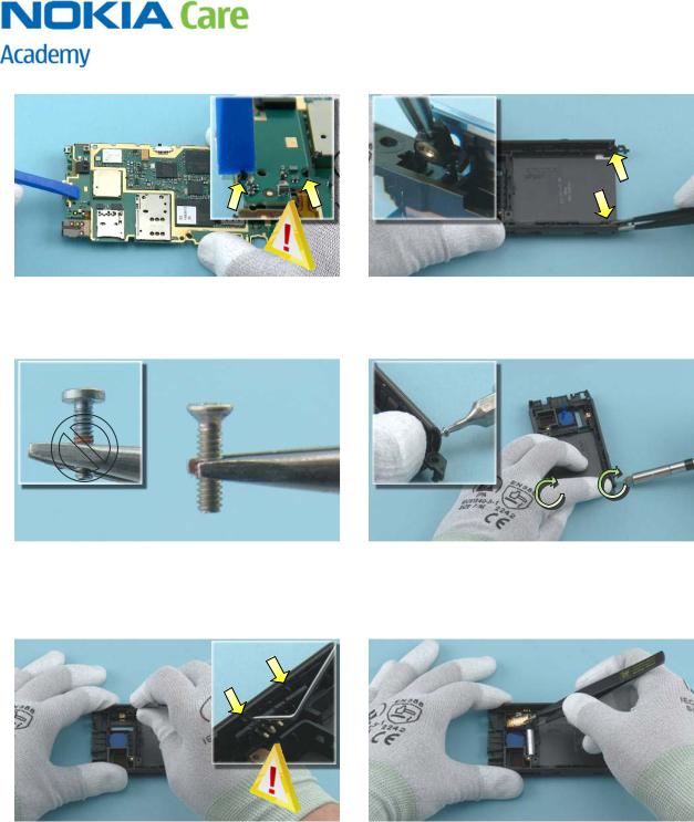
49) Remove the FLASH MODULE with the tweezers.
50) Release the SIDE SWITCH with the denta Remove it with the tweezers.
51) Unscrew the Torx+ size 4 screw to release the FIXING NUT.
52) Remove the screw and the FIXING NUT tweezers.
53) To release the second FIXING NUT, unscrew the |
54) Remove the screw with the tweezers. |
Torx+ size 4 screw. |
|
21 |
Confidential | Copyright © 2010 Nokia | All rights reserved |
Version 1.0 |

Nokia N8-00
RM-596
Service Manual Level 1&2
55) Remove the FIXING NUT. |
56) The Nokia N8-00 disassembly is now co |
-END OF DISASSEMBLY-
22 |
Confidential | Copyright © 2010 Nokia | All rights reserved |
Version 1.0 |
10. ASSEMBLY INSTRUCTIONS
1) Nokia N8-00 assembly.
3) When inserting the CAMERA MODULE, check that the shown clip is on the same side as the guiding notch. Press the CAMERA MODULE carefully to attach the camera retaining clips.
5) Press the SUB PWB SUPPORT along the edges with the SS-93 to activate the adhesive.
Nokia N8-00
RM-596
Service Manual Level 1&2
2) For assembling you need the Nokia Standard Toolkit version 2.
4) Place a new SUB PWB SUPPORT to the ENGINE BOARD by using the shown guiding pin.
6) Place the SUB PWB on top of the SUB PWB SUPPORT. Be careful not to damage the flex!
7) Press the SUB PWB carefully with the SS-93. Make sure the two clips shown are locked.
9) Note that there are two different TORX+ size 4 screw heads used in this device. The first two screws are countersunk heads.
Nokia N8-00
RM-596
Service Manual Level 1&2
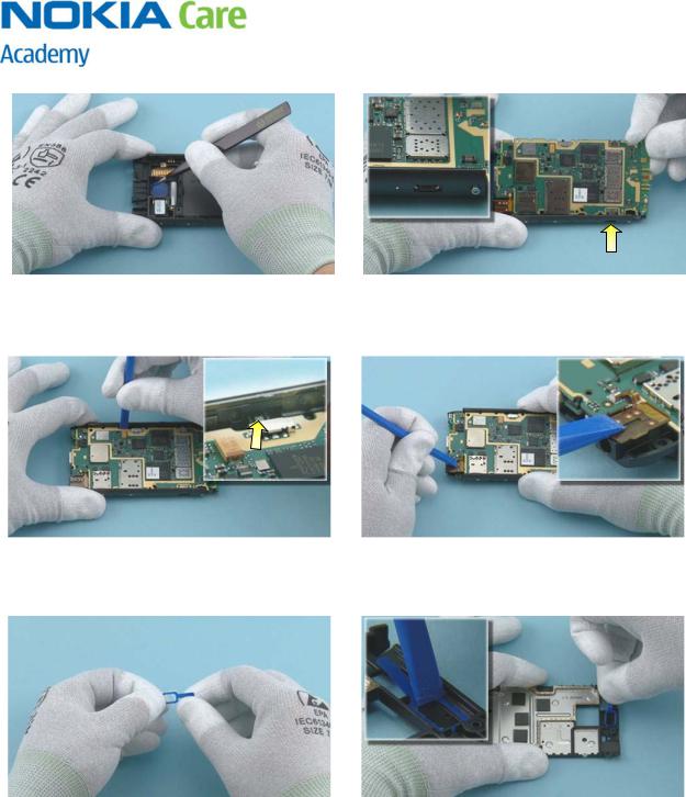
8) Insert the two FIXING NUTS.
10) Hold the FIXING NUTS in place with your finger. Tighten the two TORX + size 4 screws until the FIXING NUTS stay in place. Do not tighten them completely! If the screws are tightened too much the BOTTOM COVER cannot be assembled.
11) Place the SIDE SWITCH with the tweezers. Use the dental tool to lever the SIDE SWITCH under the two shown clips. Be careful not to injure yourself with the sharp end of the dental tool!
12) Place the FLASH MODULE with the tweezers.

Nokia N8-00
RM-596
Service Manual Level 1&2
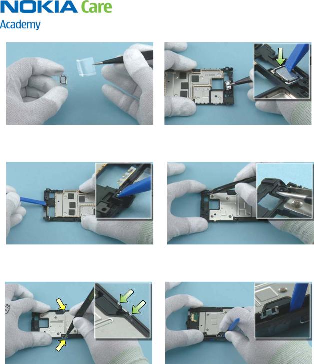
13) Push down the FLASH MODULE with the SS-93 to attach the three clips.
15) Insert the SD CARD HATCH by using the same procedure as with the SIM CARD HATCH.
17) Place the IHF GASKET with the tweezers. Press it down carefully with the SS-93 to activate the adhesive.
14) Insert the SIM CARD HATCH fastener into the BODY ASSY cavity. Then press the SIM CARD HATCH into place.
16) Remove the IHF GASKET protective film.
18) Place the IHF SPEAKER. Make sure that the IHF SPEAKER springs point towards the FLASH MODULE. Press the speaker with the SS-93 to activate the adhesive.
Nokia N8-00
RM-596
Service Manual Level 1&2
19) Remove the camera lens protective film with the tweezers.
21) Lower down the other side of the ENGINE BOARD. Make sure the LOCK KEY is placed as shown in the small picture.
23) Remove the EARPIECE ADHESIVE protective film.
20) To insert the ENGINE BOARD to the BODY ASSY, first insert the side where the USB CONNECTOR is located.
22) Press the AV CONNECTOR with the SS-93 until it snaps into place.
24) Use the tweezers to place the EARPIECE ADHESIVE. Activate the adhesive by carefully pressing down on it with the SS-93. Remove the blue EARPIECE ADHESIVE protective film.
Nokia N8-00
RM-596
Service Manual Level 1&2
25) Remove the new EARPIECE from the protective film.
27) Insert the DC JACK with the tweezers and firmly press down on it with the SS-93 until it moves into its socket.
29) When placing the two WINDOW FRAME FIXING SPRINGS, press down on the shown places to get the springs correctly in their place.
26) Place the EARPIECE and press it with the SS-93 to activate the adhesive.
28) Place the FRONT CAMERA BOOT ASSY.
30) Use the SS-93 to spread the sides of the BODY ASSY and push down the ENGINE CHASSIS ASSY to lock the springs.
Nokia N8-00
RM-596
Service Manual Level 1&2
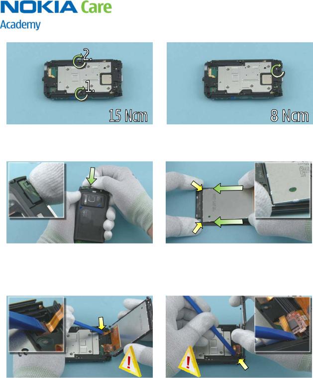
31) Tighten the two TORX + size 6 screws to the torque of 15 Ncm in the order shown.
33) Push the COMBO ANTENNA into place.
35) Hold the WINDOW ASSY as shown. Connect the DISPLAY CONNECTOR by pressing down on it carefully with the SS-93. Be careful not to damage the connector or components nearby!
32) Tighten the TORX + size 6 screw to the torque of 8 Ncm.
34) Remove the display protective film and lower down the other end of the DISPLAY. Align the DISPLAY to the WINDOW ASSY according to the small edge on the WINDOW ASSY. Press and slide fingers along the sides of the DISPLAY to activate the adhesive.
36) Connect the WINDOW ASSY CONNECTOR by carefully pressing it down with the SS-93. Be careful not to damage the connector or components nearby!
Nokia N8-00
RM-596
Service Manual Level 1&2
37) Carefully place down the WINDOW ASSY. Make sure that the connectors remain connected!
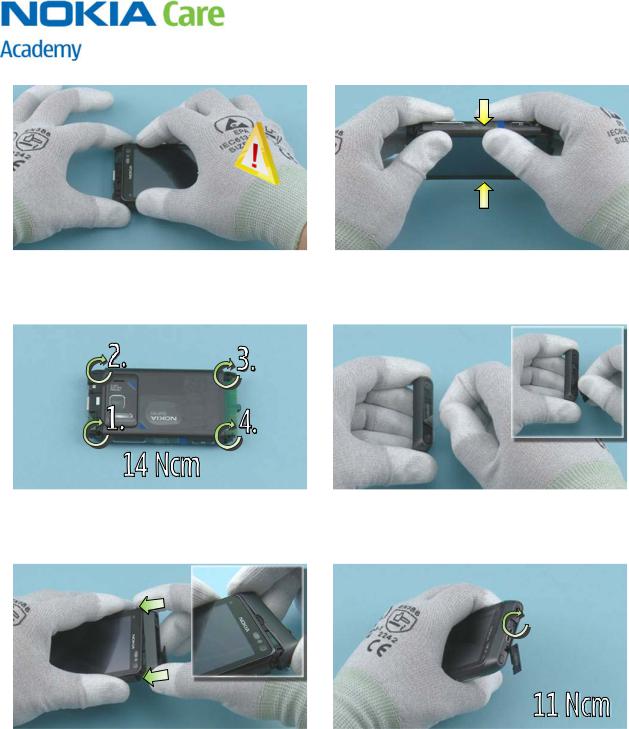
39) Tighten the four TORX + size 4 screws to the torque of 14 Ncm in the order shown.
41) Push the TOP COVER into place and close the HDMI HATCH. Make sure that the TOP COVER is in its place by firmly pressing on both corners of the TOP COVER.
38) Press the WINDOW ASSY from both sides to get the WINDOW FRAME FIXING SPRINGS locked.
40) Remove the protective film from the TOP COVER and open the HDMI HATCH.
42) Tighten the TORX + size 5 screw to the torque of 11 Ncm.
Nokia N8-00
RM-596
Service Manual Level 1&2
43) Close the HDMI HATCH and check that the TOP COVER edges are attached properly.
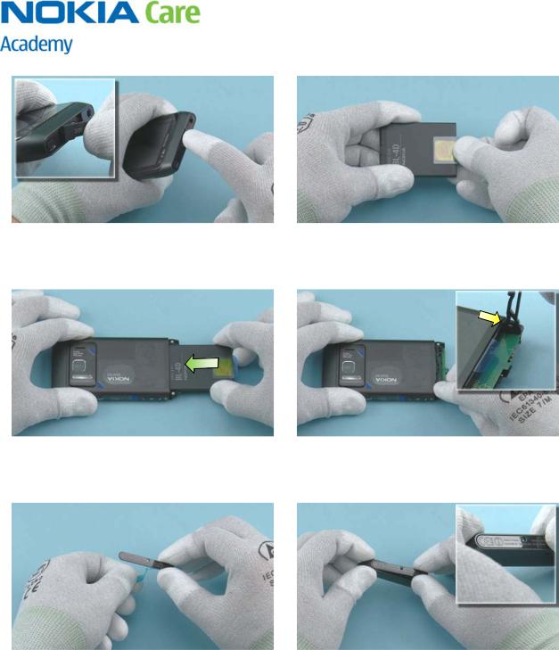
45) Insert the BATTERY as shown.
47) Remove the protective film of the BOTTOM DECO ASSY.
44) Place the BATTERY PULL-OUT TAPE to the BATTERY as shown. Press it down slightly to activate the adhesive.
46) Place the shown end of the BATTERY LID and then lower down the other end. Note that the BATTERY PULL-OUT TAPE is left under the BATTERY LID.
48) And attach it to the BOTTOM COVER.