


Package characteristics |
STM32F105xx, STM32F107xx |
|
|
6 Package characteristics
6.1Package mechanical data
In order to meet environmental requirements, ST offers these devices in different grades of ECOPACK® packages, depending on their level of environmental compliance. ECOPACK® specifications, grade definitions and product status are available at: www.st.com.
ECOPACK® is an ST trademark.
82/104 |
DocID15274 Rev 7 |

STM32F105xx, STM32F107xx |
Package characteristics |
|
|
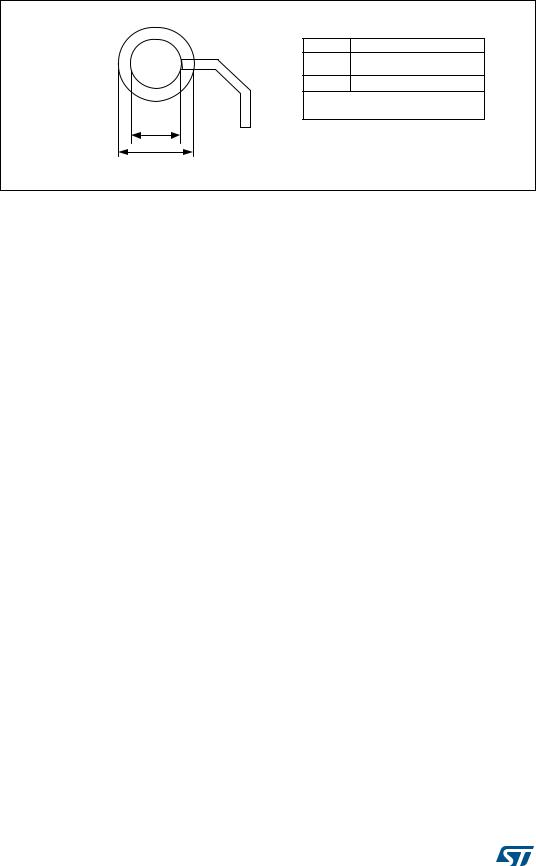
Figure 39. LFBGA100 - 10 x 10 mm low profile fine pitch ball grid array package outline
Table 58. LFBGA100 - 10 x 10 mm low profile fine pitch ball grid array package mechanical data
Dim. |
|
mm |
|
|
|
inches(1) |
|
Min |
Typ |
Max |
|
Min |
Typ |
Max |
|
|
|
||||||
|
|
|
|
|
|
|
|
A |
- |
- |
1.700 |
|
- |
- |
0.0026 |
|
|
|
|
|
|
|
|
A1 |
0.270 |
- |
- |
|
0.0004 |
- |
- |
|
|
|
|
|
|
|
|
A2 |
- |
1.085 |
- |
|
- |
0.0017 |
- |
|
|
|
|
|
|
|
|
A3 |
- |
0.30 |
- |
|
- |
0.0005 |
- |
|
|
|
|
|
|
|
|
A4 |
- |
- |
0.80 |
|
- |
- |
0.0012 |
|
|
|
|
|
|
|
|
b |
0.45 |
0.50 |
0.55 |
|
0.0007 |
0.0008 |
0.0009 |
|
|
|
|
|
|
|
|
D |
9.85 |
10.00 |
10.15 |
|
0.0153 |
0.0155 |
0.0157 |
|
|
|
|
|
|
|
|
D1 |
- |
7.20 |
- |
|
- |
0.0111 |
- |
|
|
|
|
|
|
|
|
E |
9.85 |
10.00 |
10.15 |
|
0.0153 |
0.0155 |
0.0157 |
|
|
|
|
|
|
|
|
E1 |
- |
7.20 |
- |
|
- |
0.0111 |
- |
|
|
|
|
|
|
|
|
e |
- |
0.80 |
- |
|
- |
0.0012 |
- |
|
|
|
|
|
|
|
|
F |
- |
1.40 |
- |
|
- |
0.0022 |
- |
|
|
|
|
|
|
|
|
ddd |
|
0.12 |
|
|
|
0.0002 |
|
|
|
|
|
|
|
|
|
eee |
|
0.15 |
|
|
|
0.0002 |
|
|
|
|
|
|
|
|
|
fff |
|
0.08 |
|
|
|
0.0001 |
|
|
|
|
|
|
|
|
|
N (number of balls) |
|
|
|
100 |
|
|
|
|
|
|
|
|
|
|
|
1. Values in inches are converted from mm and rounded to 4 decimal digits.
DocID15274 Rev 7 |
83/104 |
Package characteristics |
STM32F105xx, STM32F107xx |
|
|
Figure 40. Recommended PCB design rules (0.80/0.75 mm pitch BGA)
'SDG PP
'VP PP W\S GHSHQGV RQ VROGHU PDVN UHJLVWUDWLRQ WROHUDQFH
6ROGHU SDVWH PP DSHUWXUH GLDPHWHU
1RQ VROGHU PDVN GHILQHG SDGV DUH UHFRPPHQGHG
WR PLOV VFUHHQ SULQW
'SDG
'VP
06 9
84/104 |
DocID15274 Rev 7 |
STM32F105xx, STM32F107xx |
Package characteristics |
|
|
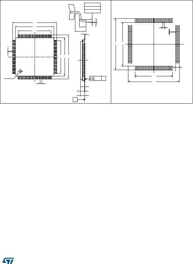
Figure 41. LQFP100, 100-pin low-profile quad flat package outline(1)
Figure 42. Recommended footprint(1)(2)
|
|
|
|
|
0.25 mm |
|
|
|
|
|
|
|
|
0.10 inch |
|
|
|
|
|
|
|
|
GAGE PLANE |
|
|
|
|
|
|
|
|
k |
|
75 |
51 |
|
D |
|
|
|
|
|
|
|
|
D1 |
|
|
|
L |
|
76 |
50 |
|
|
|
|
|
|
|
|
0.5 |
|
D3 |
|
|
|
L1 |
|
|
|
|
|
|
|
|
|
|
|
|
|
75 |
51 |
|
|
C |
|
|
|
|
|
|
|
|
|
|
|
0.3 |
76 |
|
50 |
|
|
|
|
|
|
|
|
|
|
|
|
16.7 |
14.3 |
|
b |
|
|
|
|
|
|
|
|
|
|
E3 |
E1 |
E |
|
|
|
|
|
|
|
|
|
|
|
100 |
26 |
|
|
|
|
|
|
|
|
1.2 |
|
|
|
|
|
|
|
1 |
25 |
100 |
|
26 |
|
|
|
|
|
12.3 |
Pin 1 |
1 |
25 |
|
|
|
|
|
|
|
|
ccc |
C |
|
|
|||
identification |
|
|
|
|
|
|
||
|
|
|
|
|
|
|
16.7 |
|
|
|
|
|
|
|
|
|
|
|
|
e |
|
|
A1 |
|
|
|
|
|
|
|
|
|
|
ai14906 |
|
|
|
|
|
|
|
|
|
|
|
|
|
|
|
A2 |
|
|
|
|
|
|
|
|
A |
|
|
|
|
|
SEATING PLANE |
C |
|
|
|
||
|
|
|
|
|
|
|
|
|
|
|
|
|
|
|
1L_ME |
|
|
1.Drawing is not to scale.
2.Dimensions are in millimeters.
Table 59. LQPF100 – 100-pin low-profile quad flat package mechanical data
Symbol |
|
millimeters |
|
|
inches(1) |
|
|
Typ |
Min |
Max |
Typ |
Min |
Max |
||
|
|||||||
|
|
|
|
|
|
|
|
A |
- |
- |
1.60 |
- |
- |
0.063 |
|
|
|
|
|
|
|
|
|
A1 |
- |
0.05 |
0.15 |
- |
0.002 |
0.0059 |
|
|
|
|
|
|
|
|
|
A2 |
1.40 |
1.35 |
1.45 |
0.0551 |
0.0531 |
0.0571 |
|
|
|
|
|
|
|
|
|
b |
0.22 |
0.17 |
0.27 |
0.0087 |
0.0067 |
0.0106 |
|
|
|
|
|
|
|
|
|
c |
- |
0.09 |
0.20 |
- |
0.0035 |
0.0079 |
|
|
|
|
|
|
|
|
|
D |
16.00 |
15.80 |
16.20 |
0.6299 |
0.622 |
0.6378 |
|
|
|
|
|
|
|
|
|
D1 |
14.00 |
13.80 |
14.20 |
0.5512 |
0.5433 |
0.5591 |
|
|
|
|
|
|
|
|
|
D3 |
12.00 |
- |
- |
0.4724 |
- |
- |
|
|
|
|
|
|
|
|
|
E |
16.00 |
15.80 |
16.20 |
0.6299 |
0.622 |
0.6378 |
|
|
|
|
|
|
|
|
|
E1 |
14.00 |
13.80 |
14.20 |
0.5512 |
0.5433 |
0.5591 |
|
|
|
|
|
|
|
|
|
E3 |
12.00 |
- |
- |
0.4724 |
- |
- |
|
|
|
|
|
|
|
|
|
e |
0.50 |
- |
- |
0.0197 |
- |
- |
|
|
|
|
|
|
|
|
|
L |
0.60 |
0.45 |
0.75 |
0.0236 |
0.0177 |
0.0295 |
|
|
|
|
|
|
|
|
|
L1 |
1.00 |
- |
- |
0.0394 |
- |
- |
|
|
|
|
|
|
|
|
|
k |
3.5° |
0° |
7° |
3.5° |
0° |
7° |
|
|
|
|
|
|
|
|
|
ccc |
|
0.08 |
|
|
0.0031 |
|
|
|
|
|
|
|
|
|
1. Values in inches are converted from mm and rounded to 4 decimal digits.
DocID15274 Rev 7 |
85/104 |
Package characteristics |
STM32F105xx, STM32F107xx |
|
|
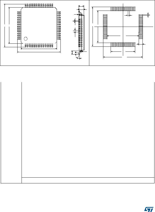
Figure 43. LQFP64 – 64 pin low-profile quad flat package outline(1)
Figure 44. Recommended footprint(1)(2)
|
|
A |
|
48 |
|
33 |
|
|
A2 |
|
|
|
|
|
|
A1 |
|
|
|
0.3 |
|
|
|
49 |
0.5 |
32 |
|
|
|
|
|
|||
E |
E1 |
b |
12.7 |
10.3 |
|
|
|
|
|
||||
|
|
e |
|
|
10.3 |
|
|
|
|
|
64 |
|
17 |
|
|
|
|
|
|
1.2 |
|
D1 |
|
|
1 |
|
16 |
|
L1 |
c |
|
7.8 |
|
|
|
D |
|
|
|
||
|
|
|
|
|
||
|
|
|
|
|
|
|
|
|
L |
|
|
12.7 |
|
|
|
|
|
|
|
|
|
|
ai14398b |
|
|
ai14909 |
|
1.Drawing is not to scale.
2.Dimensions are in millimeters.
Table 60. LQFP64 – 64 pin low-profile quad flat package mechanical data
Dim. |
|
mm |
|
|
inches(1) |
|
|
Min |
Typ |
Max |
Min |
Typ |
Max |
||
|
|||||||
|
|
|
|
|
|
|
|
A |
- |
- |
1.60 |
- |
- |
0.0630 |
|
|
|
|
|
|
|
|
|
A1 |
0.05 |
- |
0.15 |
0.0020 |
- |
0.0059 |
|
|
|
|
|
|
|
|
|
A2 |
1.35 |
1.40 |
1.45 |
0.0531 |
0.0551 |
0.0571 |
|
|
|
|
|
|
|
|
|
b |
0.17 |
0.22 |
0.27 |
0.0067 |
0.0087 |
0.0106 |
|
|
|
|
|
|
|
|
|
c |
0.09 |
- |
0.20 |
0.0035 |
- |
0.0079 |
|
|
|
|
|
|
|
|
|
D |
- |
12.00 |
- |
- |
0.4724 |
- |
|
|
|
|
|
|
|
|
|
D1 |
- |
10.00 |
- |
- |
0.3937 |
- |
|
|
|
|
|
|
|
|
|
E |
- |
12.00 |
- |
- |
0.4724 |
- |
|
|
|
|
|
|
|
|
|
E1 |
- |
10.00 |
- |
- |
0.3937 |
- |
|
|
|
|
|
|
|
|
|
e |
- |
0.50 |
- |
- |
0.0197 |
- |
|
|
|
|
|
|
|
|
|
θ |
0° |
3.5° |
7° |
0° |
3.5° |
7° |
|
|
|
|
|
|
|
|
|
L |
0.45 |
0.60 |
0.75 |
0.0177 |
0.0236 |
0.0295 |
|
|
|
|
|
|
|
|
|
L1 |
- |
1.00 |
- |
- |
0.0394 |
- |
|
|
|
|
|
|
|
|
Number of pins
N
64
1. Values in inches are converted from mm and rounded to 4 decimal digits.
86/104 |
DocID15274 Rev 7 |