


AT24C01C/AT24C02C
Revision History
11.Revision History
Revision A (November 2018)
Updated to the Microchip template. Microchip DS20006111 replaces Atmel document 8700. Corrected
tLOW typo from 400 ns to 500 ns. Corrected tAA typo from 550 ns to 450 ns. Updated Part Marking Information. Updated the "Software Reset" section. Added ESD rating. Removed lead finish designation.
Updated trace code format in package markings. Added a figure for “System Configuration Using Two Wire Serial EEPROMs”. Updated "Block Diagram" figure. Added POR recommendations section. Updated section content throughout for clarification. Updated the 8U3 1 VFBGA package drawing. Updated the PDIP, SOIC, TSSOP, SOT23 and UDFN package drawings to Microchip format.
Atmel Document 8700 Revision H (December 2016)
•Part marking SOT23:
–Moved backside mark (YMXX) to front side line2.
–Added @ = Country of Assembly
Atmel Document 8700 Revision G (January 2015)
•Add the UDFN extended quantity option.
•Update part markings, package drawings, ordering information, template, and reorganize.
Atmel Document 8700 Revision F (June 2012)
•Corrected ordering codes:
–AT24C01C-WWU11, Die Sale to AT24C01C-WWU11M, Wafer Sale.
–AT24C02C-WWU11, Die Sale to AT24C02C-WWU11M, Wafer Sale.
•Removed WDT from ordering code detail.
•Updated Atmel logos and disclaimer page.
Atmel Document 8700 Revision E (May 2012)
•Updated data sheet template.
•Added AT24C01C to document.
•Electrical performance improvements:
–Reduced all ISB from legacy values.
–Increased 1MHz frequency range to include 2.5V operation.
•Updated package drawings to latest versions (where applicable) and selected waveforms.
Atmel Document 8700 Revision D (August 2010)
Changed AT24C02C-XHM Part Marking from C02CM@ to 02CM @.
Atmel Document 8700 Revision C (July 2010)
•Ordering Information:
–Changed Atmel AT24C02C-TSUM-T to Atmel AT24C02C-STUM-T.
–Changed Atmel AT24C02CY6-MAHM-T to Atmel AT24C02C-MAHM-T.
–Changed Atmel AT24C02CU3-CUM-T to Atmel AT24C02C-CUM-T.
•Catalog numbering scheme, changed TS = SOT23 to ST = SOT23.
© 2018 Microchip Technology Inc. |
Datasheet |
DS20006111A-page 39 |

AT24C01C/AT24C02C
Revision History
•Part marking SOT23:
–Changed 2CMWU to 2CMBU.
–Changed W = Write Protection Feature to B = Write Protection.
•Part marking PDIP and SOIC: Added @ = Country of Assembly.
•Part marking TSSOP: Replaced and removed bottom mark.
•Part marking UDFN: Added HM@.
•Removed preliminary status.
•Changed tI Max 40 to 50 in Table AC Characteristics.
Atmel Document 8700 Revision B (February 2010)
Corrected catalog numbering scheme and ordering information.
Atmel Document 8700 Revision A (December 2009)
Initial release of this document.
© 2018 Microchip Technology Inc. |
Datasheet |
DS20006111A-page 40 |
AT24C01C/AT24C02C
The Microchip Web Site
Microchip provides online support via our web site at http://www.microchip.com/. This web site is used as a means to make files and information easily available to customers. Accessible by using your favorite Internet browser, the web site contains the following information:
•Product Support – Data sheets and errata, application notes and sample programs, design resources, user’s guides and hardware support documents, latest software releases and archived software
•General Technical Support – Frequently Asked Questions (FAQ), technical support requests, online discussion groups, Microchip consultant program member listing
•Business of Microchip – Product selector and ordering guides, latest Microchip press releases, listing of seminars and events, listings of Microchip sales offices, distributors and factory representatives
Customer Change Notification Service
Microchip’s customer notification service helps keep customers current on Microchip products. Subscribers will receive e-mail notification whenever there are changes, updates, revisions or errata related to a specified product family or development tool of interest.
To register, access the Microchip web site at http://www.microchip.com/. Under “Support”, click on “Customer Change Notification” and follow the registration instructions.
Customer Support
Users of Microchip products can receive assistance through several channels:
•Distributor or Representative
•Local Sales Office
•Field Application Engineer (FAE)
•Technical Support
Customers should contact their distributor, representative or Field Application Engineer (FAE) for support. Local sales offices are also available to help customers. A listing of sales offices and locations is included in the back of this document.
Technical support is available through the web site at: http://www.microchip.com/support
© 2018 Microchip Technology Inc. |
Datasheet |
DS20006111A-page 41 |
AT24C01C/AT24C02C
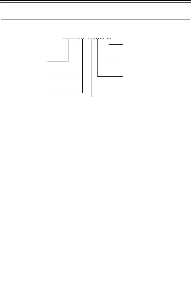
Product Identification System
To order or obtain information, e.g., on pricing or delivery, refer to the factory or the listed sales office.
A T 2 4 C 0 1 C - S S H M - T
Product Family
24C = Standard I2C-compatible
Serial EEPROM
Device Density
01 = 1 Kilobit
02 = 2 Kilobit
Device Revision
Examples
Shipping Carrier Option
T = Tape and Reel, Standard Quantity Option E = Tape and Reel, Extended Quantity Option B or Blank = Bulk (Tubes)
Operating Voltage
M = 1.7V to 5.5V
Device Grade or Wafer/Die Thickness
H or U = Industrial Temperature Range (-40°C to +85°C)
11 = 11mil Wafer Thickness
Package Option
SS |
= SOIC |
X |
= TSSOP |
MA |
= 2.0mm x 3.0mm UDFN |
P |
= PDIP |
ST |
= SOT23 |
C |
= VFBGA |
WWU= Wafer Unsawn
Device |
Package |
Package |
Package |
Shipping Carrier Option |
Device Grade |
|
|
|
Drawing |
Option |
|
|
|
|
|
Code |
|
|
|
|
AT24C01C PUM |
PDIP |
P |
P |
Bulk (Tubes) |
Industrial |
|
|
|
|
|
|
Temperature |
|
AT24C01C SSHM B |
SOIC |
SN |
SS |
Bulk (Tubes) |
||
(-40°C to 85°C) |
||||||
|
|
|
|
|
||
AT24C01C SSHM T |
SOIC |
SN |
SS |
Tape and Reel |
|
|
|
|
|
|
|
|
|
AT24C02C SSHM T |
SOIC |
SN |
SS |
Tape and Reel |
|
|
|
|
|
|
|
|
|
AT24C01C-XHM-B |
TSSOP |
ST |
X |
Bulk (Tubes) |
|
|
|
|
|
|
|
|
|
AT24C02C-XHM-T |
TSSOP |
ST |
X |
Tape and Reel |
|
|
|
|
|
|
|
|
|
AT24C01C-MAHM-T |
UDFN |
Q4B |
MA |
Tape and Reel |
|
|
|
|
|
|
|
|
|
AT24C01C-MAHM-E |
UDFN |
Q4B |
MA |
Extended Qty. Tape and |
|
|
|
|
|
|
Reel |
|
|
|
|
|
|
|
|
|
AT24C02C-MAHM-E |
UDFN |
Q4B |
MA |
Extended Qty. Tape and |
|
|
|
|
|
|
Reel |
|
|
|
|
|
|
|
|
|
AT24C02C-STUM-T |
SOT23 |
NMB |
ST |
Tape and Reel |
|
|
|
|
|
|
|
|
|
AT24C02C-CUM-T |
VFBGA |
8U3-1 |
C |
Tape and Reel |
|
|
|
|
|
|
|
|
© 2018 Microchip Technology Inc. |
Datasheet |
DS20006111A-page 42 |