


STM32F105xx, STM32F107xx |
Package characteristics |
|
|
6.2Thermal characteristics
The maximum chip junction temperature (TJmax) must never exceed the values given in
Table 9: General operating conditions on page 36.
The maximum chip-junction temperature, TJ max, in degrees Celsius, may be calculated using the following equation:
TJ max = TA max + (PD max × ΘJA)
Where:
•TA max is the maximum ambient temperature in ° C,
•ΘJA is the package junction-to-ambient thermal resistance, in ° C/W,
•PD max is the sum of PINT max and PI/O max (PD max = PINT max + PI/Omax),
•PINT max is the product of IDD and VDD, expressed in Watts. This is the maximum chip internal power.
PI/O max represents the maximum power dissipation on output pins where: PI/O max = Σ (VOL × IOL) + Σ((VDD – VOH) × IOH),
taking into account the actual VOL / IOL and VOH / IOH of the I/Os at low and high level in the application.
Table 61. Package thermal characteristics
Symbol |
Parameter |
Value |
Unit |
|
|
|
|
|
|
|
Thermal resistance junction-ambient |
46 |
|
|
|
LQFP100 - 14 × 14 mm / 0.5 mm pitch |
|
||
ΘJA |
|
°C/W |
||
|
|
|||
Thermal resistance junction-ambient |
45 |
|||
|
|
|||
|
LQFP64 - 10 × 10 mm / 0.5 mm pitch |
|
||
|
|
|
||
|
|
|
|
|
|
Thermal resistance junction-ambient |
40 |
|
|
|
LFBGA100 - 10 × 10 mm / 0.8 mm pitch |
|
||
|
|
|
||
|
|
|
|
|
ΘJA |
Thermal resistance junction-ambient |
46 |
°C/W |
|
LQFP100 - 14 × 14 mm / 0.5 mm pitch |
||||
|
Thermal resistance junction-ambient |
45 |
|
|
|
LQFP64 - 10 × 10 mm / 0.5 mm pitch |
|
||
|
|
|
||
|
|
|
|
6.2.1Reference document
JESD51-2 Integrated Circuits Thermal Test Method Environment Conditions - Natural Convection (Still Air). Available from www.jedec.org.
DocID15274 Rev 7 |
87/104 |

Package characteristics |
STM32F105xx, STM32F107xx |
|
|
6.2.2Selecting the product temperature range
When ordering the microcontroller, the temperature range is specified in the ordering information scheme shown in Table 62: Ordering information scheme.
Each temperature range suffix corresponds to a specific guaranteed ambient temperature at maximum dissipation and, to a specific maximum junction temperature.
As applications do not commonly use the STM32F103xx at maximum dissipation, it is useful to calculate the exact power consumption and junction temperature to determine which temperature range will be best suited to the application.
The following examples show how to calculate the temperature range needed for a given application.
Example 1: High-performance application
Assuming the following application conditions:
Maximum ambient temperature TAmax = 82 °C (measured according to JESD51-2),
IDDmax = 50 mA, VDD = 3.5 V, maximum 20 I/Os used at the same time in output at low level with IOL = 8 mA, VOL= 0.4 V and maximum 8 I/Os used at the same time in output
at low level with IOL = 20 mA, VOL= 1.3 V PINTmax = 50 mA × 3.5 V= 175 mW
PIOmax = 20 × 8 mA × 0.4 V + 8 × 20 mA × 1.3 V = 272 mW This gives: PINTmax = 175 mW and PIOmax = 272 mW: PDmax = 175 + 272 = 447 mW
Thus: PDmax = 447 mW
Using the values obtained in Table 61 TJmax is calculated as follows:
–For LQFP100, 46 °C/W
TJmax = 82 °C + (46 °C/W × 447 mW) = 82 °C + 20.6 °C = 102.6 °C This is within the range of the suffix 6 version parts (–40 < TJ < 105 °C).
In this case, parts must be ordered at least with the temperature range suffix 6 (see
Table 62: Ordering information scheme).
Example 2: High-temperature application
Using the same rules, it is possible to address applications that run at high ambient temperatures with a low dissipation, as long as junction temperature TJ remains within the specified range.
Assuming the following application conditions:
Maximum ambient temperature TAmax = 115 °C (measured according to JESD51-2),
IDDmax = 20 mA, VDD = 3.5 V, maximum 20 I/Os used at the same time in output at low level with IOL = 8 mA, VOL= 0.4 V
PINTmax = 20 mA × 3.5 V= 70 mW PIOmax = 20 × 8 mA × 0.4 V = 64 mW
This gives: PINTmax = 70 mW and PIOmax = 64 mW: PDmax = 70 + 64 = 134 mW
Thus: PDmax = 134 mW
88/104 |
DocID15274 Rev 7 |
STM32F105xx, STM32F107xx |
Package characteristics |
|
|
Using the values obtained in Table 61 TJmax is calculated as follows:
–For LQFP100, 46 °C/W
TJmax = 115 °C + (46 °C/W × 134 mW) = 115 °C + 6.2 °C = 121.2 °C This is within the range of the suffix 7 version parts (–40 < TJ < 125 °C).
In this case, parts must be ordered at least with the temperature range suffix 7 (see
Table 62: Ordering information scheme).
|
|
|
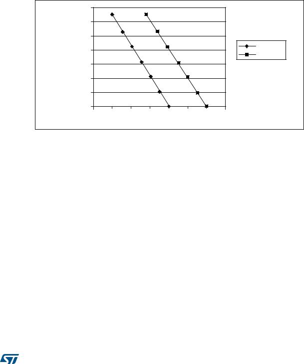
Figure 45. LQFP100 PD max vs. TA |
|||||
|
ϳϬϬ |
|
|
|
|
|
|
|
|
ϲϬϬ |
|
|
|
|
|
|
|
|
ϱϬϬ |
|
|
|
|
|
|
|
;ŵt |
ϰϬϬ |
|
|
|
|
|
|
^ƵĨĨŝdž ϲ |
|
|
|
|
|
|
^ƵĨĨŝdž ϳ |
||
|
|
|
|
|
|
|
||
|
|
|
|
|
|
|
|
|
|
ϯϬϬ |
|
|
|
|
|
|
|
W |
|
|
|
|
|
|
|
|
|
|
|
|
|
|
|
|
|
|
ϮϬϬ |
|
|
|
|
|
|
|
|
ϭϬϬ |
|
|
|
|
|
|
|
|
Ϭ |
|
|
|
|
|
|
|
|
ϲϱ |
ϳϱ |
ϴϱ |
ϵϱ |
ϭϬϱ |
ϭϭϱ |
ϭϮϱ |
ϭϯϱ |
|
|
|
|
d ;Σ |
|
|
D^ϯϯϯϱϴsϭ |
|
DocID15274 Rev 7 |
89/104 |