

reading / British practice / Vol D - 1990 (ocr) ELECTRICAL SYSTEM & EQUIPMENT
.pdf"NrIP"-
Auxiliaries systems
former. Whilst operation for faults on the LV side of the transformer circuit is desirable, the relay cannot distinguish between these and faults on the outgoing circuits from the 3.3 kV switchboard. To calculate the setting for the high set instantaneous relay, proceed as follows.
- RELAY OPERATING CHARACTERISTIC Referring to Fig 11.56 (b), we know that the RMS value of l Ac, expressed in MVA, is 107.1 N1VA. We
need to calculate the value of the DC component and hence the peak current.
|
= time, s |
T |
= circuit time constant, s |
[DC |
l Ac exp( - t/T) |
|
|
|
|
RELAY |
|
|
|
|
|
|
CURRENT |
|
|
|
|
|
|
|||
|
|
lop |
||||
|
PG. 11.54 Relay overshoot |
|||||
|
Overshoot = 4.1 - t7: |
|||||
|
where t2 = relay operating time at l op |
|||||
[ 2 |
ti me when switching from l op to I the relay |
|||||
just does not operate |
||||||
|
||||||
|
= 85 177o of relay setting current (usually) |
|||||
The reactance to the fault is 0.08 + 0.01333 = 0.09333 p.u., assuming that R is 0.00667 p.u., making X/R = 14 (tan - 1(14) = 86 ° ). For 50 Hz, w = 314. Therefore T= X/Rw = 14/314 = 0.0446. The first peak occurs at (t = 0.01 s),
exp( t/T) = exp( - 0.01/0.0446) = 0.799
Therefore IDC = 'AC X 0.799 and NC |
rAC |
'DC |
The formula for the envelope AA" is |
|
|
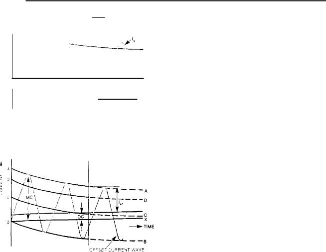
,1/4,11 Jepend on the X/R ratio of the fault circuit and point-on-wave at which the fault occurs. This facor can lead to relays operating for faults outside
-le intended protective zone and is called transient erreach.
The definition of transient overreach is the differ- , , Le between the RMS value of the steady state cur-
v,hich when steadily increased will operate the relay and the RMS value of current which, when fully r et by point-on-wave switching, will just operate the
Hay (f op ) expressed as a percentage of I cp (see Fig
1.56 (a)), i.e., (Is - Iop)/Top X 100%. If, for exam-
-. e, f s = 2 A and l op = 2/1.05 A, the overreach
.;ualS 5 6'0 and a setting of 2.1 A on the relay would 7.2%ent operation for currents less than 2 A. This is - et a practical setting as no allowance has been made
. .,1r errors in relays, current transformers and inrush
...rrents on transformers and motor circuits, the CEGB , ouId therefore use a minimum setting of 1.5 x 2 =
Consider an instantaneous relay on the HV side of 'le 10 MVA 11/3.3 kV transformer (Fig 11.52) with fault current through it as shown on Fig 11.56 (b). Ple 10 MVA transformer has an 8% reactance. As- -Arne the 11 kV busbar fault level is 750 MVA which,
•\Pressed as a per unit impedance, is Z = 10/750 =
. 01333.
So, the fault level on the 3.3 kV side is 10/(0.08 + 1333 ) = 107.1 MVA. The AC component of the
irrent waveform, expressed in MVA is 107.1 MVA. IS required to find the magnitude of the first peak
hat the relay setting can be determined which will
.01 operate for faults on the LV side of the trans-
' MC= 'AC x (1 + exp -t/T) lAc x (1.799)
Using this formula,
!AC = \12 x 1.799 x 107.1
=2.55 x 107.1
=273.1 MVA.
So, on this system to avoid the first peak of 273.1 MVA, a relay responding to the peak currents would need to be set above 273.1 MVA, preferably at (2.9 x 107.1) = 310.6 MVA, whereas using a relay with a transient overreach of 5% at an angle between the fault current and system voltage greater than 86 ° , a factor of 1.5 would allow for errors and magnetising inrush currents. On relays with overreach quoted at angles less than 86 ° , a factor of 2 should be used if the system fault angle exceeds 86 ° .
The settings for the three types of relay to ensure grading would be:
• No quoted overreach |
310.6 MVA. |
•5% to 10% overreach >86 ° 160.6 MVA.
•5% to 10% overreach >86 ° 214.2 MVA.
Modern electronic relays will give 5% at 84 ° and 10% at 88 ° .
This brings in the need to use relays with low transient overreach, so that a setting as close as possible to the through-fault setting of 107.1 MVA can be achieved.
937

Protection |
Chapter 11 |
|
00'
'Co
CURRENT MVA
Fin. 11.55 Protection grading for phase fault relay-to-fuse, demonstrating non-grading at low fault levels.
12.9.7 Techniques to obtain close co-ordination between protection stages
Fuse to fuse
Section 12.9.1 recommends that the choice of fuses should be restricted to the characteristic bands of IEC 269 (BS88). The pre-arcing and total operating time characteristic plus tolerance (± 10%) must lie inside the characteristic band of IEC 269 (BS88).
I f the circuit is a motor circuit, providing that the pre-arcing characteristic of the fuse selected does not lie outside the lower band of BS88, the same current rated fuses of different manufacture can be interchanged without losing co-ordination through ageing of the fuse. Fuse ageing is caused by frequent operation into the fuse pre-arcing time and will cause operation of the fuse at lower current values than specified.
This can incur delays whilst the cause of the fuse blowing is being investigated or even loss of production if the motor is being brought on in an emergency.
As an alternative to using the BS88 bandwidths for grading, it is possible to use the manufacturer's published data for a particular fuse. This generally gives a much narrower operating bandwidth and a possible reduction in the 2:1 principle for discrimination, thus achieving closer grading, faster fault clearance times and smaller fuse sizes in the fuse switch on a motor circuit, with consequent better protection.
If this course is adopted, the user must ensure that only fuses from the same manufacturer and of the same type are used for replacements. To do otherwise would invalidate the overall discrimination. Taking into account the long lifetime of the equipment being protected, the continued availability of a particular fuse is not guaranteed. Also there is a real possibility that the user unwittingly replaces a fuse with a different make without first checking its characteristic, with a possible risk of losing discrimination. Using IEC 269 (BS88) as the basis avoids this risk, i.e., only fuses (including tolerances) complying with IEC 269 (BS88) are ordered and used as replacements.
938
Auxiliaries systems
11ME
• „
1 .
FIG. 11.56 Transient overreach
Part of the assessment of the protection system - %olves estimating the likely fault clearance times to
.::,ure that the plant is correctly rated (cables, switchetc.) and that no danger exists for personnel who ht be in close proximity to the faulted plant. Genthe phase to phase faults are not limiting factors these are generally high enough to cause rapid clear-
.r.,;c of the fault by the fuse. However, phase to
...ifth faults, even direct to the sheath, can be long in :caring if the cable to the protected plant is very long. ( EGB practice is that if the sheath is only earthed at sending end, then to prevent a dangerous conarising at the far end of the cable, the protection icarance time for an earth fault condition should not 'e more than 0.46 seconds. This time is based on the
:drth potential rise and duration following faults on
•
'le power station auxiliary system.
, A voltage of 650 V for 0.2 s has been internationally
. ablished and is based on experience of the I 2 R with-
and of
of a human being. Where R is the resistance of numan being and I the current flowing through the
• )(4. For back-up protection clearance times, the
(- EGB adopts a figure, based again on international :ndin gs , of 430 V. Therefore if the time allowed at
650 V is 0.2 s, then (650/430) 2 >< 0.2 = 0.46 s, is the back-up clearance time allowed,
Fuse to relay
At low voltage (4 t5 V), a relay with an extremely inverse characteristic should always be used if grading with a fuse, as the relay characteristic follows that of the fuse very closely.
If the relaying point is on the NV side of the transformer, then a three-pole overcurrent relay is always used to ensure that one phase of the relay carries the equivalent of a three-phase fault current, irrespective of whether the fault, if on the LV side, involves two or three phases. The relay will then always operate in three-phase fault current operating time for all phase to phase faults on the LV side of the transformer. When co-ordinating the fuse and the relay, the grading interval has to be maintained when the fuse is carrying phase to phase fault current and the relay is carrying the equivalent three-phase fault current, i.e., 2/., 3 ti mes the fuse current. The exercise in the next Section 12.9.8, will show that no adjustments are necessary to allow for the difference in operating currents due to the rounding upwards of the current and time multiplier settings (TMS) to obtain a practical relay setting.
If the relay grading with the fuse is for earth fault protection and the relaying point is at 415 V, the current setting range must be made high enough. For instance, a setting range of 10-40% on an earth fault relay will not allow grading with a 200 A fuse since a setting of at least 75 070 is required. The grading of the earth fault relay with a 630 A fuse requires a setting of at least 100 070, or preferably 120%. This is illustrated in Fig 11.57.
A higher current setting on the phase fault relay at a lower time multiplier will give faster operation at the higher fault levels. Considering Fig 11.58, the relay can be set at 120% TMS 0.45 or 150% TMS 0.2. The reason that the 120% setting requires a 0.45 TMS and not 0.275 as would be required for grading at the highest fault level, is that grading is not being achieved at the lower fault level and this can be seen by reference back to Fig 11.55, where it is demonstrated that relay 2 would not grade at point X. With the 150 070 and 200% settings, the grading is determined by the minimum operating time of the relay.
In Section 12.9.1 of this chapter, it is stated that closer grading can be obtained if the combined characteristics of the thermal relay and the fuse are taken into account. At 415 V, this will rarely occur, since the majority of the circuits are controlled by contactors and the main protection is the fuse in the fuse switch. At 3.3 kV, fuses and switches are co-ordinated to give a full fault clearance capability, allowing the use of instantaneous relays. This means that the circuitbreaker handles faults up to 50 MVA but above this level the fuse operates. The co-ordination is by time. The operating time of the circuit-breaker and protec-
939

Protection |
|
Chapter 11 |
|
-
10
CURRENT. MVA
FIG. 11.57 Grading of earth fault relays
tion (80 ms) at this fault level is always longer than the fuse operating time (65 ms), see Fig 11.58. it may also mean that, with one transformer supplying the board, which is normal, the circuit-breaker could clear the fault due to the limited fault infeed and only when two transformers are paralleled will the fuse be required to interrupt the fault. With this combination, the relay on the bus-section circuit only needs to grade with the point of intersection of the thermal relay and high set instantaneous relay at the lower fault level, and not the fuse. This is explained as follows.
Figure 11.55 shows the three characteristics, consisting of a thermal relay with a high set instantaneous relay on a 1 MVA motor at 3.3 kV and a 400 A fuse combination. The shaded portion is the operating area. The 3.3 kV bus-section overcurrent relay has to be set at 150% to grade with the high set on the motor and the overcurrent relay on the incoming 5 MVA trans-
former has to be set to 200% to grade with the 3.3 kV bus-section relay. if the bus-section relay (3) was grading with the fuse, its plug setting would have to be about 250% and relay (4) 325 07o. Figure 11.58 shows relay (3) set at 150% and relay (4) at 200 07o. This is the maximum size of motor (1500 kW) that the protection can grade without using a very high setting on the incoming transformer overcurrent. The alternative may be to use differential protection on the motor to get a lower setting if the overcurrent relay on an outgoing 3.3/0.415 kV transformer is not the limiting factor for relay (3) (as it is in this instance, i.e., relay (3) cannot get closer to relay (2)).
415 V motor protection
Motors at 415 V are commonly switched by a contactor and protected by a combination of a thermal relay and
940

Auxiliaries systems
I0 |
1 00 |
CLIIIIRENT.MVA
FIG. 11.58 Protection grading for phase fault relay-to-fuse, demonstrating faster operation at high fault levels.
.. fuse. Larger motors, requiring relatively large fuses +.n excess of 200 A) need extra protection against earth ' Ats, since the fuse cannot safely cope with low values or earth fault current. For an example of an application
additional protection |
to contactor circuits, consider |
he 630 A fuse on the |
100 kW motor. A contactor is |
- equired which will meet the following requirements |
|
ontinuous rating of 200 A (20% overload on full load
.urrent of 162 A), and has a capability to meet the cut- off current of the 630 A fuse at 24.09 MVA (see Table [1 .1). Assume the duty required of the contactor is to
\C3 duty in |
BS5424. This means a breaking current of |
, ix times the |
AC3 duty of the contactor quoted by the |
manufacturer. A typical figure could be 190 A for a 200 ontactor, giving a figure of 1140 A. Referring to Fig
11 .) 9 , it can be seen that the earth fault relay would
• ave to be delayed in excess of 100 seconds even if the :use characteristic lay close to the minimum pre-arcing
: .me of the fuse to ensure the contactor is not called , Pon to clear a fault above its rating. The solution is
to provide a definite time earth fault relay with a fast operating time (300 ms) and prevent its operation above the contactor rating (see Fig 11.59) by means of an instantaneous relay. Ideally, the fuse should clear all faults above the contactor rating and the protection should initiate opening of the contactor for faults within its rating. The fuse, however, is selected for its ability to withstand the motor starting current peaks and consequently fault clearance by the fuse may be slow not to correspond to the motor full load current for some faults above the contactor rating. For phase to phase faults, fuse protection is usually adequate and the addition of the earth fault relay covers for earth faults.
A range of special motor circuit fuselinks are available which are physically smaller than the standard general purpose fuselink. These fuselinks are given a dual rating, e.g., 200M315. A fuselink with this designation is rated to operate at 200 A continuously but has a time current characteristic for short-circuits that falls within the standardised zone for a 315 A fuse.
941

Protection |
|
|
|
|
|
|
|
Chapter 11 |
||
|
|
|
|
|
|
|
|
|
||
|
|
|
|
|
|
|
|
|
|
|
|
|
|
TABLE 11.1 |
|
|
|
|
|
|
|
|
|
Plant protection data |
|
|
|
|
|
|||
|
|
|
|
|
|
|
|
|
|
|
|
|
|
Maximum |
|
|
CT |
High set |
Rela y |
|
|
|
|
Device type |
fault |
|
CT ratio |
primary |
relay |
|
||
|
|
|
setting |
|
|
|||||
|
|
current |
|
current |
current |
|
||||
|
|
|
|
|
MVA |
|
|
|||
|
|
|
MVA |
|
|
MVA |
MVA |
|
||
|
|
|
|
|
|
|
|
|||
|
|
|
|
|
|
|
|
|
|
|
|
(1) |
415 V ruse 630, A |
24.09 |
|
|
|
|
|
|
|
|
(2) |
XIDMT 3 3 kV/415 V, 1.6 N1VA |
250 |
|
300/1 |
1.71 |
36.14 |
2.06 |
|
|
|
(I) |
XIDNIT 3.3 kV bus-section |
125 |
|
2000/1 |
I1.43 |
|
11.43 |
|
|
|
(4) |
1 DNIT 11/3.3 kV 10 MVA |
750 |
|
600/1 |
11.43 |
187.9 |
17.14 |
|
|
|
(5) |
I DNIT 11 kV bus-section |
321 |
|
3000/1 |
57.16 |
|
57,16 |
|
|
|
(6) |
I DNIT 23.5/11 kV, 60 MVA |
8000 |
|
1500/1 |
61,05 |
484 |
78.32 |
|
|
|
|
|
|
|
|
|
|
|
|
|
10000
1000 -
100 -
|
|
|
|
|
|
|
|
|
|
SETTING OF |
|
|
|
||
|
|
|
|
|
|
|
|
|
|
INSTANTANEOUS... |
|
|
|
||
|
|
INSTANTANEOUS EARTH FAULT |
|
OVERCURRENT |
|
|
|
|
|
||||||
|
|
PROTECTION + 100rns TIME DELAY |
|
INHIBIT |
|
|
|
|
|||||||
|
|
|
|
|
|
|
|
|
|
TOTAL FAULT |
|
|
|
|
|
|
|
|
|
|
|
|
|
|
|
CLEARANCE TIME |
|
|
|
||
|
|
|
|
|
|
|
|
|
FOR EARTH FAULT |
|
|
|
|||
|
|
|
|
|
|
|
|
|
|
|
|
|
|
|
|
0 1 |
|
|
CONTACTOR OPERATING |
|
|
|
|
|
|
|
|
|
|||
|
|
|
|
TIME t |
|
|
|
|
|
|
|
|
|
||
|
|
|
|
|
|
|
|
|
|
|
|
|
|
|
|
0o1 |
|
|
|
|
|
|
|
|
|
|
|
|
|
|
|
|
|
|
|
|
|
|
|
|
|||||||
|
|
10 |
100 |
1000 |
10000 |
1 00000 |
|||||||||
|
|
|
|
|
|
|
|
|
|
CURRENT A |
|
|
|||
---- COMPOSITE PROTECTION CURVE USED FOR GRADING
Ho. 11.59 415 V motor circuit protection co-ordination
Use of these fuses therefore requires less space for the fuses in a starter for a given motor size, or a given fuse accommodation will allow a larger motor to be operated. However, the latter mode of operation could permit a cut-off current and energy let-through in excess of the proven and certified rating of the equipment concerned. This aspect must be considered and satisfied for every application of motor circuit fuselinks, preferably at the design stage.
12.9.8 Application to a typical system
From the system diagram, a path is chosen that gives the highest settings for current grading. A typical path
is shown in Fig 11.52; from the largest fuse at 415 V through the section switch at 3.3 kV, onto the I I kV busbar via the largest transformer, onto the 3.3 kV busbar and then through the bus-section switches at 11 kV. This ensures that all the bus-section switches are set to grade with any outgoing circuit and all the incoming transformers will grade with the section switches.
Since the grading depends on the largest fuse it is essential to allocate fuses to circuits. Non-motor circuits must ensure that the fuse will protect the cable. This means that the fuse must have a rating above the cable continuous rating but that a fault on the cable must be cleared before the whole cable receives
942

Reliability
|
„nano( damage. Phase to phase faults are cleared |
|||
|
|
by the fuse so are not a limitation. Phase |
||
|
fau lts, however, could be low and may take |
|||
|
j lorig. time io clear. The cable size and length |
|||
|
|
that .1 |
,,hort-circuit to the sheath at the |
|
• |
hc |
pf the .;ible is cleared by the fuse in less |
||
|
||||
|
|
|||
|
0.46 |
ee previous section); this ensures that |
||
|
|
do not occur on the cable |
||
|
|
|
||
|
niu t |
circuits, the fuse selection is more |
||
|
• The following must be considered: |
|||
|
|
|||
• |
f- },2 [herrnal capability of a fuse must withstand two |
|||
,•,•,[1,,ceutive motor starts without any potential deter- |
||||
|
,,r,ition |
in subsequent performance. |
||
• |
foior full load current, as determined from the |
|||
1%erage efficiencies and power factors recommended |
||||
|
• |
3 of IECTC2. |
||
|
ri Table |
|||
• |
Nominal motor starting currents, as calculated from |
|||
, kW ratio/1.73 kV, using the ratio of starting |
||||
|
||||
|
\.• to output kW derived from Table 41 of BS4999, |
|||
|
r.irt 4 1 . |
|
|
|
• |
k‘erae motor run-up time, as determined from |
|||
|
Aupirical |
formula 3 + kW/7.46 in Table 1 of BS587 |
||
|
:or times |
up to 5 s and rounded up to nearest 10 s |
||
|
imurn for times greater than 5 s. |
|||
• |
the permissible deviations of not more than 10% in |
|||
|
terms of current from fuse manufacturers published |
|||
Lurves, as allowed in BS88 Part 2 1975.
•the fuse characteristic curve bandwidths, as defined
iiiBS88 1975.
I or example, consider the 100 kW motor on the system
Full load current |
162 A |
Nominal start (BS4999 ratio) |
780 kVA |
Starting current |
1085 A |
Starting time 3 + kW/7.46 |
10 s |
Assuming two starts |
20 s |
I Qmination of Fig 11.50 gives a fuse size of 630 A The following steps are taken to determine settings
. or he relays (current and time multipliers) to obtain
, o-ordination between the relays and the (relays +
Table 11.2 must now be drawn up for all the relays the fuses on the path must be chosen, determining
he high set instantaneous relay settings as described in he previous section. The procedure is as follows:
•Column 1 is self-explanatory.
•Column 2 is determined from Section 12.9.6 of this chapter, e.g., for the 1.6 MVA transformer, the highest setting current is 1.3 )( full load current of he transformer, i.e., 2.08 MVA. Therefore, 125%
(2.06) the nearest relay tap setting, is suitable for this relay.
•Columns 3 and 4 also derive from Section 12.9.6; column 3 is the nearest high set overcurrent relay setting or, if there is no relay, the maximum fault current through the IDNIT relay. For example, the fuse grading current and cut-off MVA is the maximum fault MVA, from Table 11.2, i.e., 24.09 MVA.
•Column 5 is the current setting multiple at the grading point. For example, grading the bus-section with the 1.6 MVA transformer, the grading current ( MVA) (column 4) is the setting of the high set on the 1.6 MVA transformer (36.14 MVA). This is 17.72 ti mes the 1.6 MVA transformer relay setting and 3.17 ti mes the setting of the bus-section relay.
•Column 6 is derived directly from column 5, using the characteristic curve for an extremely inverse relay with a time setting multiplier of 0.45, already determined when grading it with the fuse.
•Column 7 uses the grading equation, i.e., 1.25 x 0.17 = 0.46s.
•Column 8 is obtained by using the value for Relay 2 in column 5 and the characteristic curves for an inverse time relay to obtain the time in column 7. Completed results are shown in Table 11.2 with additional explanations to derive the values in the columns.
All grading points have been checked for phase to phase faults. No alterations in settings had to be carried out since the nearest time multiplier and current setting multiplier in an increased direction had been selected. Figure 11.53 and Table 11.3 give the computer grading curves. If the time multipliers are rounded up to the nearest step, 0.025, the pick-up and time setting multiplier figures compare exactly with columns 2 and 8 in Table 11.2.
13 Reliability
In order that protection equipment can operate efficiently and without interruption throughout life, it is essential that it must possess the highest possible reliability and availability. In this context, it should be remembered that protection is normally quiescent but must operate reliably 'first time'. It is vital, not only that the equipment is installed and operated in the prescribed manner and in the right service conditions, but also that it receives regular attention in line with manufacturer's recommendations.
Records of relay unreliability show that the majority of failures are attributable to bad connections between components by way of dry solder joints, broken conductors, defective connector contacts and faulty wiring, etc. It is acknowledged that it is virtually impossible to avoid all hardware failures in a protection system, but the probability of such events happening is reduced by careful design and by the adoption of good quality assurance procedures by the
943

414
TABL1 11.2
Determination of system protection settings
|
Column (see notes) |
1 |
2 |
3 |
4 |
|
5 |
6 |
7 |
8 |
|
|
|
|
|
|
|
|
|
|
|
||
|
|
|
|
Relay |
Fault |
Current setting |
Operating |
Operating |
Time |
||
|
|
Relay |
MVA |
multiple at grading |
ti me relay |
ti me relay |
mull iplier |
||||
|
Stage and device type |
cut-off, |
MVA for |
|
point |
in front, s |
to be graded, s |
setting |
|||
|
type |
selling |
|
||||||||
|
|
MVA |
grading |
|
|
|
|
|
|
||
|
|
|
|
|
|
|
(Relay 1) |
(Relay 2) |
|
||
|
|
|
|
|
|
Relay l |
|
Relay 2 |
("1' MS) |
||
|
|
|
|
|
|
|
|
|
|
|
|
(1) 415 V fuse 630 A |
|
|
24.09 |
|
|
|
|
|
|
|
|
(2) |
1.6 MVA transformer |
XIDMT |
2,04(120%) |
36.14 |
24.09 |
|
|
11.81 |
|
0.23 |
0.45 |
(3) |
Bus-section, 3.3 kV |
1 DMT |
11.43(100%) |
125.00 |
36.14 |
17.72 |
|
3.17 |
0.17 |
0.46 |
0.125 |
(4) |
10 MVA transformer, 11/3.3 kV |
1 DMT |
17.15(150%) |
187.90 |
125.00 |
10.94 |
|
7.29 |
0.33 |
0.66 |
0.200 |
(5) |
Bus-section, 11 kV |
1 0MT |
57.16(100%) |
323.00 |
187.90 |
10.96 |
|
3.29 |
0.54 |
0.94 |
0.175 |
(6) |
60 MVA transformer, 23.5/11 kV |
1 DMT |
76.32(125%) |
484.00 |
323.0 |
5.65 |
|
4.23 |
0.70 |
1.13 |
0.250 |
|
|
|
|
|
|
|
|
|
|
|
|
Notes: • Column 4: equals column 3 value for previous stage
•Column 5, Relay I: equals column 2 value for previous stage
•Column 6: from the relay curves, read off the time from the nearest curve with settings given in column 5. Then calculate the time front Actual TMS/Curve TMS x (time from selected curve). If TMS = 0.125 take curve for 0.2 and time at 0.125 = 0A25/0.2 x (time at 0.2)
•Column 8: is column 7 divided by the operating time of Relay 2 with CSM (column 5) at nearest TMS to give column 7 time x TMS for selected curve. if column 7 -= 0.46 and the operating time at CSM (3.17 column 5) is 0.81 for TMS = 0.2, then column 8 = 0.46/0.81 x 0.2 = 0.114, giving 0.125 as the practical relay TMS
TABLE 11.3
Computer calculated relay settings
|
|
|
Pick-up, |
Current |
Grading |
Fuse |
Plug |
Time |
Thermal |
Motor full- |
|
6 |
x Overload |
Stage |
|
|
multiplier |
load current |
|
||||||||
|
|
MVA |
grading |
margin, s |
rating. A |
setting, % |
setting, % |
' |
|
trip time, s |
|||
|
|
setting |
|
||||||||||
|
|
|
|
|
|
|
|
|
MVA |
|
|
|
|
|
■ |
|
0.4528 |
|
|
630.0 |
|
|
|
|
|
|
|
|
|
|
|
|
|
|
|
|
|
|
|
||
|
|
|
2.0577 |
4.54389 |
0.24320 |
|
120.00 |
0.43594 |
|
|
|
|
|
|
|
|
11.4315 |
5.55556 |
0.33632 |
|
100.00 |
0.11520 |
|
|
|
|
|
|
|
|
17.1473 |
1.50000 |
0.34091 |
|
150.00 |
0.19325 |
|
|
|
|
|
|
|
|
57.1577 |
3.33333 |
0.43799 |
|
100.00 |
0.17914 |
|
|
|
|
|
, |
|
|
76.3184 |
1.33523 |
0.44536 |
|
125.00 |
0.23891 |
|
|
|
|
|
- -I 47 |
|
|
|
|
|
|
|
|
|||||
|
|
2.2863 |
|
|
400.0 |
|
|
|
|
|
|
|
|
00 |
|
, |
2.4006 |
|
|
|
|
|
105.00 |
2.28631 |
|
|
4.64571 |
|
|
|
|
|
|
|
|
|
|
|
|
|
|
|
|
|
|
|
Reliability |
|
|
|
|
|
|||
manufacturer. Thorough testing of installed systems is |
• |
Radio frequency interference. |
||||
a |
lso essential. |
• |
Supply variations/interruptions. |
|||
|
The design should ensure that a component is chosen |
• |
Dry heat. |
|||
so that it operates around the mid point of its overall |
||||||
|
|
|||||
rating range. Only components complying with BS9000 |
• |
Low temperature. |
||||
must be used. |
• |
Insulation resistance. |
||||
|
|
To reduce the failure rate of components such as |
|
|
||
r esistors and capacitors, each must be 'burnt-in'. Di- |
The main criterion used to evaluate the relay is a |
|||||
odes and transistors only require a spot check made |
check that the operating time of the various protection |
|||||
,n them to establish correct operation. The amount |
||||||
functions is unaffected by the application of the type |
||||||
of heat generated by components must be kept to a |
||||||
tests, that correct fault indication is given and that it |
||||||
minimum since this can adversely affect the reliability |
||||||
clears when the relay is reset. |
||||||
o f temperature dependent devices, such as transistors, |
||||||
|
However, at the present time the electromechanical |
|||||
in close proximity to them. This problem is further |
type of protection relay is still being manufactured and |
|||||
exacerbated for protection relays, because they are |
||||||
is still freely available on the commercial market. The |
||||||
always accommodated inside metal or plastic enclo- |
||||||
demand for such a relay is due mainly to the fact that |
||||||
s ures. Where there is a high risk of component failure |
||||||
users prefer to stay with equipment that they are fami- |
||||||
or non-operation, redundancy can be used to ensure |
||||||
liar with and which has shown itself to be reliable in |
||||||
that high reliability is achieved. |
||||||
operation, resulting in a high degree of confidence in |
||||||
|
|
Continuous monitoring of the hardware and inbuilt |
||||
|
|
its use and application. Added to this is the fact that |
||||
self-checking of microprocessors are now standard |
||||||
some users may wish to replicate an existing protec- |
||||||
features of most digital type protection relays to pro- |
||||||
tion scheme for a new installation which means using |
||||||
vide early detection of failure. |
||||||
electromechanical relays, thus eliminating the need for |
||||||
|
|
The reliability of solid state protection relays is |
||||
|
|
additional sets of spares with the attendant savings in |
||||
improved significantly by using digital rather than ana- |
||||||
spares holding, storage space, administrative costs and |
||||||
logue type relays. This is because large scale integrated |
||||||
the retraining of staff. |
||||||
components reduce the number of connections required |
||||||
|
Another, and perhaps more significant reason for |
|||||
considerably. Analogue relays require many more com- |
|
|||||
the demand for electromechanical relays, is the mar- |
||||||
ponents, with consequent increase in the number of |
||||||
ket in Third World countries which is influenced by |
||||||
electrical connections. |
||||||
cost and considerations of familiarity, simplicity and |
||||||
|
|
Another factor affecting reliability is the immunity |
||||
|
|
reliability. |
||||
of the relay to electromagnetic interference. A power |
||||||
|
Nevertheless as far as the CEGB is concerned, future |
|||||
station environment is very heavily polluted with elec- |
|
|||||
protection schemes will tend to be based on the use |
||||||
trical noise and it is essential that the relay is designed |
||||||
and constructed to withstand the effects of such pol- |
of solid state technology. |
|||||
lution without malfunction or non-operation. |
|
Further improvements in the quality of thermal over- |
||||
|
|
To enhance reliability, the CEGB operates a type |
load protection as applied to motors can be achieved |
|||
approval procedure which evaluates fully the perform- |
with the digital type relays which are unobtainable |
|||||
ance of the relay under both normal and abnormal |
from the electromechanical type of protection relay. |
|||||
operating conditions. This evaluation takes the form |
|
Use can be made of the temperature detectors in the |
||||
of |
type testing at the manufacturer's works and field |
stator core of the machine during the manufacturing |
||||
rials on selected circuits of the power system. Wherever |
stage. The output signals from the detectors act as |
|||||
possible, the field trials are on circuits that are likely |
inputs to the relay which, in turn, enable the thermal |
|||||
to have wide variations in operating conditions. |
model of the relay to react more quickly to changing |
|||||
|
|
Type testing not only checks the capability of the |
temperature conditions in the motor. In addition, |
|||
relay to withstand without deterioration all of the op- |
further temperature measurements can be taken of the |
|||||
erating conditions it is likely to meet when used in |
air temperature within the motor by placing detectors |
|||||
service but also ensures that the design includes a |
at both the inlet and outlet sides of the machine. An |
|||||
margin over normal service requirement. |
overload condition will give rise to an increase in air |
|||||
|
|
The following tests are typical of the type tests |
temperature at the outlet and this signal can be fed |
|||
carried out on protection relays: |
into the thermal model as above. These techniques |
|||||
• |
|
Drop. |
provide enhanced thermal overload protection and will |
|||
|
result in a significant reduction in motor winding burn- |
|||||
• |
|
Vibration. |
||||
|
outs, thus minimising the risk of costly repair/replace- |
|||||
• |
|
Electrical stress. |
ment and the resulting loss of production which this |
|||
• |
|
Impulse. |
would entail. |
|||
|
|
The electronic protection relay is generally more |
||||
• |
|
High frequency disturbance. |
|
|||
|
costly than its electromechanical counterpart. It is to |
|||||
|
|
|
|
|||
• |
|
Spark. |
be expected, however, that with the increasing accept- |
|||
945

Protection |
Chapter 11 |
|
|
ance of solid state technology and with the advances made in manufacturing techniques by the application of large scale integration, the cost of equipment will drop significantly in the foreseeable future.
The benefits of using a microprocessor-based system have already been outlined. Such a system can easily Form an integrated protection scheme which is particularly useful. The parameters contained in each protection relay can be fed into a junction unit local to the plant and then to a supervisory microcomputer local to the plant, or to some other remote location. The linking of each individual relay into the microcomputer system enables better information to be presented to the operator whilst allowing the ongoing process of monitoring and supervising of the protective system to proceed without affecting the basic level
of protection. The system must be designed so that, in the event of a fault occurring in the supervisory computer, the protection reverts to the individual protection fitted to each motor. This ensures that under this type of failure mode, the motor is always protected.
Figure 11.60 illustrates a simplified scheme for an integrated protection system. The exploitation of the facilities provided by existing microprocessor-based protection relays to form an integrated system, where a group of motors can be monitored from a central point, is seen as a significant future development.
The link between the supervisory computer and the protection junction will be hard wired, although the prospect of using fibre-optic over long distances and in a noisy electrical environment will be reviewed.
|
|
4 |
|
a am= |
co |
Cl -a; atPiZI,C. |
||
|
1 |
1 |
|
: |
m .j1r- |
IMP |
M 1=1 |
!ElarI.Se.Mfr-4.1 |
( |
|
0 |
m |
mmm Nu |
wayammois |
|||
|
|
|
|
|
mmmmm |
• MfM1•1011/MM =ma |
||
CENTRAL SUPERVISORY COMPUTER
11 kV MOTOR PROTECTION
RELAY
|
|
|
|
|
|
|
|
|
|
|
|
|
|
PRINTER |
|
I |
|
|
|
|
|
|
|
|
|
|
|
|
|
|
|
|
|
|
|
|
|
|
|
|
|
|
|
|
|
|
|
|
|
|
|
|
|
|
MAIN |
|
|
|
|
|
|
|
|
|
|
|
|
|
JUNCTION BOX |
111 111 |
|
|
|
|
|
|
|
|
|
|
|
|
|
|
|
|
|
|
|
|
|
|
|
|
|
|
|
EWINHEMillaiNE |
|
|
|
|
|
|
|
|
|
|
|
|
|
|
HARDWIRE |
|
|
|
|
|
|
|
|
|
|
|
|
3 3kV MOTOR PROTECTION
RELAYS
|
|
OPTIONAL DISPLAYS |
|
|
FIBRE-OPTIC |
|
|
|
|
|
HARDWIRE |
|
|
|
|
|
LINK |
|
|
a i |
|
|
|
|
OHN E |
|
41 W |
|
|
|
|
|
|
|
|
|
|
|
|
MOTOR |
|
|
|
|
|
PROTECTION |
|
|
|
|
|
RELAYS |
|
'JUNCTION aox
Fro. II.60 Plant monitoring data link system
946