

reading / British practice / Vol D - 1990 (ocr) ELECTRICAL SYSTEM & EQUIPMENT
.pdf
|
|
|
|
|
Cranes |
|
|
|
|
|
|
||
|
|
power su pply and distribution |
These protective devices are arranged to trip the |
|||
|
|
|
|
|
||
3.2 |
|
|
Ehree-phase three-wire 50 Hz supply is pro- |
main supply contactor rather than the motion con- |
||
|
|
v |
tactor, since the main supply contactor is subjected |
|||
|
|
|
|
|||
\ j., "" for eac h cr adle, direct from a fuse switch in the |
to a less arduous duty and is therefore less suscep- |
|||||
|
|
II ; |
oNitchhoard serving that area. Prior to |
|||
|
|
tible to failure. An undervoltage protection system |
||||
|
|
s witchgcar being commissioned, the site |
||||
|
|
|
is fitted to the main crane supply and connected to |
|||
|
|
:ru:tion supply is used, with variations and limits |
trip the main supply contactor when the voltage drops |
|||
11 |
|
ailed in Section 2.1.2 of this chapter. |
below the operating capability of the motor, i.e., |
|||
VIc415 \, ,Lipply is connected by cable to a main |
80% of the nominal value (see Section 2.2 of this |
|||||
|
|
|
Switch which ts readily accessible from the |
|||
|
|
Lng |
chapter). |
|||
III |
operating floor. From there, it is extended by |
The main isolating switch, main supply contactor, |
||||
the downshop conductor system and thence to |
||||||
|
|
motion contactors and all protection equipment are |
||||
|
|
:0 |
|
|
||
|
,:rane , On the crane is located a further isolating |
housed in sheet-steel cubicles mounted on the bridge |
||||
|
|
which supplies the crane drive motors through |
of the crane. |
|||
|
|
,A)ntactors. Fuse protection is provided on mdi- |
||||
|
|
|
||||
jil |
supplies. Particular attention is paid to |
|
||||
of fuses fitted to the 415 V main supply |
3.3.3 Motion control — direction |
|||||
|
rat ing |
|||||
..\ ieliboard and those on the crane to ensure adequate |
Motion directional control is provided by a three-phase, |
|||||
|
|
|
|
|
||
!Jun discrimination. |
triple-pole reversing-type contactor connected to reverse |
|||||
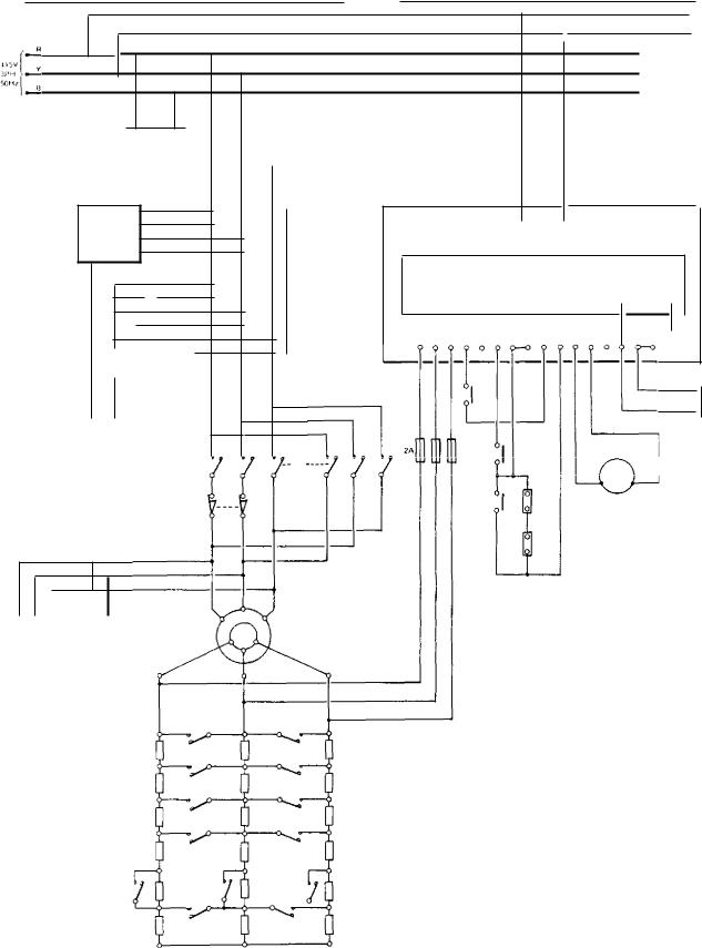
Figures 10.2 and 10.3 show a typical crane supply |
t wo of the three phases of the drive motor supply. This |
|||||
.trtd distribution system. |
contactor is manufactured to 3S5424 [10] and ESI |
|||||
|
|
|
|
|
Standard 37-1 [11] and is electrically and mechanically |
|
3 3 Crane motor drives |
interlocked to ensure that only one direction can be |
|||||
selected at any time. |
||||||
33.1 |
|
Motors |
3.3.4 Motion control — speed |
|||
v i riable-speed motors are normally provided for the |
||||||
Speed control of slipring induction motor drives is |
||||||
;, r wcipal crane motions, i.e., main hoist, auxiliary hoist |
||||||
achieved by a number of motor accelerating contactors |
||||||
fitted), long-travel and cross-traverse. For the ma- |
||||||
controlled by timer devices, which progressively short- |
||||||
only of applications, 415 V. three-phase 50 Hz induc- |
||||||
circuit resistances connected in the rotor circuit to give |
||||||
':. , a motors are used; either slipring (with switched |
||||||
the required acceleration and final speed. This is the |
||||||
toior-resistances) or squirrel-cage types (with thyristor |
||||||
most common system in use on power station cranes |
||||||
speed control systems). For constant-speed drives, |
||||||
and is shown on Fig 10.2. |
||||||
Iiirrel-cage induction motors are normally used, these |
||||||
Alternative systems for the speed control of squirrel- |
||||||
Hri started direct-on-line. |
||||||
cage induction motors include solid state variable- |
||||||
For certain applications in nuclear power stations, |
||||||
frequency or voltage control equipment. |
||||||
210 V DC motors are used, these requirements being |
||||||
High integrity, high availability cranes, or cranes |
||||||
Iscussed in Section 3.10 of this chapter. Motors are |
||||||
utilised for close tolerance fitting operations, are pro- |
||||||
.n accordance with British Standards BS5000 flj and |
||||||
vided with a creep speed control system, in addition to |
||||||
10,4999 [2], as appropriate. They are totally-enclosed, |
||||||
the normal speed control system. A typical creep speed |
||||||
|
protection to 1P54 for indoor cranes and to 1P55 |
|||||
|
control system consists of a closed-loop in which an |
|||||
eatherproof for outdoors. |
||||||
For main hoist, auxiliary hoist, long-travel and cross- |
eddy-current brake with variable-torque-speed char- |
|||||
acteristics is coupled to the shaft of the slipring induc- |
||||||
't:t+erse applications involving cyclic operation, motors |
||||||
tion motor and used to control its speed within close |
||||||
.Lt.: suitable for 150 starts per hour and are of duty |
||||||
tolerances (in the order of ± 1%). The motor is ac- |
||||||
•:. pe S4 or S5 to B54999 Part 30 [2], with a minimum |
||||||
|
|
duration factor of 25%. To cater for long slow |
celerated up to the rated speed under rotor-resistance |
|||
|
|
control. By comparing the motor slipring voltage with |
||||
|
main and auxiliary hoist motors are capable of |
|||||
..ontinuous operation on the first notch speed. |
a reference voltage, the difference between the desired |
|||||
|
|
|
|
|
and actual motor speeds is determined, the error signal |
|
33.2 |
|
Motor protection |
then being amplified and fed to a thyristor firing cir- |
|||
|
cuit to vary the amount of braking. By continuous |
|||||
')hort |
|
|
|
|
||
|
.:ircuit protection on the motor supplies is pro- |
monitoring of the speed difference signal, the output |
||||
Jed by |
|
|
speed variation is restricted to close limits. In the event |
|||
|
|
by high breaking capacity (HBC) cartridge fuses |
||||
'0 I3S88 [9]. Motor protection is afforded by magnetic |
of failure of the creep speed system, the drive reverts |
|||||
0 ercurrent relays, fitted with adjustable inverse time |
to the basic rotor-resistance system. The operational |
|||||
Jelay elements connected into each of the three phases. |
integrity and safety of the motion drive is therefore |
|||||
I l otst motions are, in addition, fitted with current- |
assured, although the accuracy of speed control is |
|||||
operated single-phasing protection. |
impaired. |
|||||
807
Mechanical plant electrical services |
Ch a pter 113 |
MAIN HOIST
I6A
70 OTHER
C PEE PSP EE TI
CON rRoL
L CCP5
UNDERvOL I AilE |
|
|
SUPPLY |
|
|
||
|
|
||
PROT& C TON |
|
|
I NPUT FUSES |
|
|
|
I315A) |
SINGLE P.AASING
P Ft() IL C TIDN
CLOSED LOOP CREEP SPEED CONTROLS
CURRENT
TRANSFORMERS
OVE R CURREN r
RELAYS
MAINS SUPPL Y
CONTAC TOR
SWITCHING
MI |
|
|
REVERSING -v |
|
|
CONTACTOR |
|
|
EARTH BAR |
|
|
MAIN HOIST |
EDDY CURRENT |
|
BRAKE |
||
SERIES LIMIT SWITCH |
:IR Cur
SELECTION
CONTACTS
MAIN HOIST
MOTOR
C
EMERGENCY SERVICE
MAIN HOIST BRAKES
MAIN HOIST MOTOR
ROTOR RESISTANCE
SWITCHING NETWORK
FIG. 10.2 Typical main and auxiliary hoist supply and distribution system
808

Cranes
AUXILIARY HOIST A.
FAST |
|
CREEP |
|
||
|
Suar,
I HRu r FUSES
|
SINGLE |
|
|
THAT |
|
|
PROTEC T ION |
|
0.,EREAJRREN |
OvERCURREN |
|
RELAYS |
||
RELAYS |
||
|
||
|
EARTH BAR |
|
|
REVERSING |
|
|
Tb CONTACTOR |
|
EA ST |
'CREEP' |
|
r TWITCH |
LIMIT SWITCH |
' FAST MOTOR 'CREEP MOTOR
|
AUXILIARY HOIST |
FAST |
CREEP |
SUPPLY |
SUPPLY |
|
I NPUT FUSES |
||
itiou T FUSES |
SINGLE
PHASING
PROTECTION
SINGLE
PHASING
PRO TEC CON
EARTH BAP
REvE R ,;■ NG
CON TAG Top
OVERCU BRENT |
OVERCURRENT |
RELAYS |
RELAYS |
EARTH BAR EARTH BAR
|
REVERSING |
REVERSING |
|
CONTACTOR |
CONTACTOR |
'FAST' |
'CREEP' |
|
LIMIT SWITCH |
|
|
LIMIT SWITCH |
|
|
|
|
' FAST MOTOR |
'CREEP MOTOR |
FIG. 10.2 (cont'd) Typical main and auxiliary hoist supply and distribution system
809

Mechanical plant electrical services |
Chapter 10 |
|
MAIN TRAVERSE |
MAIN TRAVEL |
16A |
|
504 |
|
|
|
CL OSF. 0 LOOP CREEYSPFE D CONTROLS
OVE RC U RISE N
RELAYS
EARTH
BAR
 II II 24
REVERSING
CON rAC TOR
0
SELECTION
CONTACTS
MAIN
TRAVERSE
MOTOR
I I
MAIN TRAVERSE MOTOR
ROTOR RESISTANCE
SWITCHING NETWORK
MAIN TRAVEL MOTOR
ROTOR RESISTANCE
SWITCHING NETWORK
FIG. 10.3 Typical travel and traverse supply and distribution system
810

|
|
Braking systems |
|
3.3,5motions are equipped with electrically-operated |
|
|
|
or 'electromagnetic solenoid' brakes which |
|
|
3 d u ty and rating defined by BS3579 1121. The |
|
|
design ensures that the brake is auto- |
|
' |
a pplied if the supply to the associated drive |
|
|
fj ik. Fi ,2ttre5 10.2 and 10.3 show typical ar- |
|
|
'thrustor' brakes on a crane, one being |
|
|
LieLi for each travel motion and two, emergency |
|
|
,er\.ice. being provided on the main and auxiliary |
|
|
mo(ions. The brakes are supplied from the motor |
|
|
o f ihe motion contactor and provide a fail-safe |
|
|
On the hoist motions, the emergency brake |
|
|
as a back-up to the service brake, if the latter |
|
..,[. |
|
3.4 Control station systems |
||
3.4.1 Cab control |
||
|
|
control consists of a driver's cab slung under |
. |
, ne end of the crane bridge, equipped with all devices |
|
|
ary for the manual control of the crane. The |
|
|
c |
|
zt.inernent suffers from a number of disadvantages has been superseded by radio control in certain Ntations, when the operational advantages justify
•!.... additional cost.
I he disadvantages of cab control are as follows:
•The site and disposition of the cab imposes a reiriction on hoist and traverse movements.
•[he driver is positioned high above the operating floor and so cannot perform operations without :he aid of an assistant on the operating floor.
•Parking and driver access is normally restricted and —in necessitate the crane being manned for long periods during a prolonged handling sequence.
.\pkal cab control layout is shown in Fig 10.4.
controls are provided as follows:
are levers, which return to 'oil position v. I len released.
Ke ,, -operated on; off
Finervency-stop pthhbutton
) \lain hoist control
• tRiliary hoist control l ung travel control
The key has a code unique to the crane and is trapped in the 'on' position, to prevent unauthorised operation of the crane.
Described in Section 2.3.5 of this chapter.
Creep raise/slow raise/ fast raise.
Creep lower/slow lower/ fast lower.
As for main hoist.
Creep North/slow North/ fast North.
Cranes
Creep South/slow South/
fast South.
(6)Cross-traverse control Creep West/slow West/
|
|
fast West |
|
|
Creep East/slow East/fast |
|
|
East. |
(7) |
Long travel limit |
Key-operated. |
|
override |
|
(8) |
Cross-traverse limit |
Key-operated. |
|
override |
|
(9)Anti-collision system Key-operated. override
(10)Warning hooter on/off switch.
(11) |
Crane floodlights |
To floodlight operating |
|
on/off switch |
floor. |
(12) |
Crane bridge lights |
To control access lighting. |
|
on/off switch |
|
The above controls operate directly into the contactor control circuits, through a control station selection located adjacent to the 'local' controls on the
bridge-mounted protection panel.
3.4.2 Radio control
Radio control overcomes the shortcomings of cab control and offers the following advantages:
•The crane operator is at operating floor level and unrestricted, thereby enhancing crane operating efficiency.
•Parking of the crane is not governed by personnel access requirements, except for maintenance purposes.
•The full span of the bridge can he utilised for traversing and hoisting operations.
The system is not without disadvantages, however, and these are summarised below:
•Radio control is susceptible to interference and elaborate safeguards must be included in the system to prevent malfunction.
•The control system is more complex, since it requires a transmitter, receiver and interface relay equipment.
•The portable transmitter/control units are susceptible to accidental damage and abuse if their usage and storage is not strictly controlled.
An outline of the radio-control system is given below. The control functions provided by a body-worn transmitter/control unit are the same as those described in the previous section. A typical layout is shown in
Fig 10.5,
811

Mechanical plant electrical services |
Chapter 10 |
|
|
|
|
CROSS TRAVERSE CONTROL (6) |
MAIN HOIST CONTROL (3) |
|
|
CROSS TRAVERSE |
|
|
OVERRIDE (8). |
|
|
LONG |
|
|
TRAVEL LIMIT |
|
|
OVERRIDE (7). |
|
• KEY OPERATED
FIG. 10.4 Cab control layout
I |
8.19S |
|
|
|
|
I |
Loorepi |
|
|
|
|
I |
LOWER |
LOWER |
NORTH |
EAST |
•:0 \\, |
|
|
|
|
|
|
|
|
|
|
0 |
|
|
|
|
|
|
|
|
|
|
|
|
|
|
|
RAISE |
RAISE |
|
RAISE |
Lima |
SOUTH |
WEST |
OF F |
|
START mAi N |
AUX |
LPGHTS ASS |
OVER- |
|
|
|
|
|
HOIST |
ALARM HOIST A. |
HOIST '13' RIDE |
TRAVEL |
TRAVERSE |
ON |
|||
|
|
|
|
|
|
|
|
|
Flo. 10.5 Radio transmitter control layout
Radio control systems are VHF, UHF or, more usually, LF, and comprise a transmitter/control unit, which is carried by the crane operator on a waist/ shoulder harness, plus a receiver and interface relay equipment, the last two items being located on the crane bridge. Contacts on the interface relays are connected through sequence relay equipment to operate the crane control contactors.
A typical LF radio control system uses coded, con- tinuously-transmitted multi-frequency signals to safeguard against malfunction of the crane due to external interference. For each crane control to function, a
minimum of three radio frequency signals and a master security-frequency signal must be transmitted simultaneously. Unique control frequencies are allocated to each crane to safeguard against the incorrect matching of transmitter and crane. As a further safeguard, the transmitter range is limited to approximately 60 m.
3.4.3 Pendant contra!
The simplest and most economic means of crane control is by pendant control station. Applications are necessarily limited to lower-capacity cranes, such as
812

Cranes
ed in diesel generator houses and ancillary
t hose us where lifting needs are relatively small plant houses,
d limited.
In The control station is either of the double-insulated ,aitern, with a metal insert to give mechanical strength, '„ a metal case shrouded in rubber. Pushbuttons are trouded to prevent accidental operation and are self-
.c , L,(t i ng when released. A typical pendant control sta-
:on is shown in Fig 10.6.
. An earth continuity conductor is incorporated in the -endant supply cable and is connected to the control :iaiion metal insert or box.
3.5 Crane controls, interlocks and limit switches
3,5.1 Control equipment cubicles
The control equipment is housed in a suite of cubicles ri lounted on the crane bridge: it comprises protec-
!i on equipment, stator contactor controlgear, rotor ontrolgear, timing relays, sequence relays, speed conirol equipment and related electrical control equipment. These cubicles have protection to 11'54 of BS5490 [31 or indoor use and to 1P55 weatherproof in outdoor
,auations.
One of the cubicles houses the 415 V main supply holating switch. A system of coded-key interlocks is provided to prevent any of the control cubicle doors irom being opened when the main supply isolating
,itch is 'on', and to prevent the isolating switch being ,:iosed when any door is unlocked.
Figures 10.7 and 10.8 show the disposition of equip-
ment on the bridge and crab unit of an overhead travelli ng crane.
3.5.2Protective panel
One of the suite of control cubicles, the protective
panel, accommodates the 415 V main supply isolat- mg switch, the main supply contactor, motor overload protection devices, fuses, transformers, rectifiers and other components necessary for the control of the crane, a complete set of motion control pushbutton
-+I.itches for maintenance and testing purposes and a
.:onirol selector switch. The last item has four positions:
Remote
Local
Remote test
Local test
Allows the crane to be operated from the normal control panel only.
Allows the crane to be operated from the protective panel only.
Allows the crane remote control circuits to be checked, with the main supply isolating switch 'off'.
Allows the crane local control circuits to be checked, with the main supply isolating switch 'off'.
RAISE A)
L , LOWER .1
w
a
0
I ', SOU ! Ho)
A
NORTH j
a
(0 EAST 0)
WEST 0)
a
CONTROL OPERATIONAL
SWITCH
TRAVEL 6 TRAVERSE '3 LIS OVERRIDE
(o WARNING HOOTER )
1, EMERGENCY STOP
Flo. 10.6 Pendant control station
813

Mechanical plant electrical services |
Chapter I() |
|
|
CRANE PROTECTIVE PANEL
DOWNSHOP
COLLECTORS
|
MAIN HOIST RESISTOR PANEL |
|
|
MAIN HOIST |
CROSS TRAVERSE AND |
MAIN HOIST |
RESISTOR PANEL |
AUXILIARY HOIST PANEL |
CONTACTOR PANEL
CROSS TRAVERSE AND
LONG TRAVEL RESISTOR PANEL
|
|
|
MAIN HOIST |
|
|
RESISTOR PANEL |
|
|
|
LONG TRAVEL |
|
|
|
|
|
|
CONTACTOR PA NEt. |
|
|
I NT E R MEDIA TE |
|
|
RELAY PANEL |
END CARRIAGE
EASTSIDE
LONG TRAVEL CREEPSPEED
CONTROL UNIT
|
|
|
|
|
|
|
|
|
|
|
|
|
|
|
MAIN HOIST TOP |
MAIN HOIST |
|
|
|
|
|
MAIN HOIST |
|
|
|||||
|
|
|
|
SERVICE BRAKE |
|
|
|||
|
CREEP SPEED CONTROL UNIT |
SUSPENSION |
|
|
|||||
|
MAIN HOIST |
||||||||
|
|
||||||||
|
|
|
|
|
|
|
|
|
|
|
|
|
|
|
|
|
|
|
|
|
|
|
|
|
|
|
|
|
DRUM |
CROSS LEAD TOWING BRACKET • |
|
|
|
|
|
|
|||
|
|
|
|
|
|
||||
|
|
|
|
|
|
|
|
|
|
' 71 CROSS TRAVERSE
CRAB
|
|
|
|
|
NORTH SIDE |
|
SOUTH SIDE |
|
|
|
|||
|
|
|
|
|
|
|
|
|
|
|
AUXILIARY HOIST |
||
|
|
AUXILIARY HOIST |
|
|
||
|
|
|
MAINTENANCE PLATFORM |
|
||
|
|
ACCESS LADDER |
|
|
||
|
|
|
|
|
|
|
|
|
|
|
|
|
|
FIG. 10.7 Typical crane bridge layout
814

Cranes
CRANF. r4TFC TIVE |
MAIN HOIST PANEL |
STAIN HOIST RESISTANCE PANEL |
LONG TRAvEL PANEL |
|
|
|
mA, TT NANG!
.,ST KT r '
CROSS TpAvERSE AND
AUXILNR R PANEL
,• R.RVE AVE ,NNER
|
|
|
|
|
|
|
|
|
|
|
|
|
|
|
|
|
|
|
|
|
|
|
|
|
|
LI l T 5 1 |
1 5511 |
|
|
|||
|
|
|
|
|
|
|
|
|
|
|
|
|
|
|
|
|
|
|
|
|
|
|
|
|
|
|
|
|
|
|
|
|
|
|
|
|
|
|
|
|
|
|
HOIST ULTIMATE |
|
|
|
|
|
|
|
|
|
|
|
|
|
|
|
|
||||||
|
|
|
|
|
|
|
|
|
|
|
LIMIT SNITCH |
|
|
|
|
|
|
|
|
|
|
|
|
|
|
|
|
|
|
|
||
|
|
|
|
|
|
|
|
|
|
|
|
|
|
|
|
|
|
|
|
|
|
|
|
|
|
|
|
|
|
|
|
|
|
|
|
|
|
|
|
|
|
|
|
|
|
|
|
|
|
|
|
|
|
|
|
10 1S T |
|
|
|
|
|
|
|
|
|
|
|
|
|
|
|
|
|
|
|
|
|
|
|
|
|
|
|
|
|
|
|
|
MOTOR |
• |
|
|
|
|
|
|
|
|
|
|
|
|
|
|
|
|
|
|
|
|
|
|
|
|
|
|
|
|
|
|
|
I |
_ |
|
|
|
|
|
|
|
|
|
|
|
|
|
|
|
|
|
|
|
|
|
|
|
|
|
|
|
|
|
|
|
|
|
|
|
|
|
|
|
|
|
|
|
|
|
|
|
|
|
|
|
|
|
|
|
|
|
|
|
|
|
|
|
|
|
|
|
HOS rSeIIAlcE |
||||||
|
|
|
|
|
|
|
|
|
|
|
|
|
|
|
|
|
|
|
|
|
|
|
|
|
|
BR AKE |
|
|||||
|
|
|
|
|
|
|
|
|
|
|
ow+THT |
E |
|
|
|
|
|
|
|
|
|
LI |
|
|
|
|
|
|
|
|
|
|
|
A |
0 00. S. |
|
|
|
|
|
|
|
|
|
|
|
|
|
|
|
|
|
|
|
|
|
|
|
|
|
|||||
A |
K AR T HOIST |
|
|
|
|
|
|
|
|
|
|
|
|
|
|
|
|
|
|
|
|
|
|
|
|
|
|
|||||
|
|
|
|
|
|
|
|
|
|
|
|
|
|
|
|
|
|
|
|
|
|
|
|
|
|
|
|
|
|
|
|
|
|
|
|
CROSS TRAVERSE |
|
|
|
|
|
|
|
|
|
|
|
|
|
|
|
|
|
|
HOIST |
|
|
|
|
|
|
|
|
|
|
|
|
|
|
|
|
|
|
|
|
|
|
|
|
|
|
|
|
|
|
|
|
|
|
|
" A.'" |
|
|
|
||||
|
|
|
GEARBOX |
|
|
|
|
|
|
|
|
|
|
|
|
|
|
|
|
|
GEARBOX |
|
|
|
|
|
||||||
|
|
|
|
|
|
|
|
|
|
|
|
|
|
|
|
|
|
|
|
|
|
|
|
|
|
|
|
|
TCN |
|
|
|
|
|
|
|
|
|
|
|
|
|
|
|
|
|
|
|
|
|
|
|
|
|
|
|
|
|
|
|
|
|
|
|
|
|
|
|
|
|
|
|
|
|
|
|
|
|
|
|
|
|
|
|
|
|
|
|
|
|
|
|
|
|
|
|
|
|
|
|
|
CROSS TRAVERSE |
|
|
|
|
|
|
|
|
|
|
|
|
|
|
|
|
|
|
|
|
|
|
|
|
|
|
|||
|
|
|
|
|
|
|
|
|
|
|
|
|
|
|
|
|
|
|
|
|
|
|
|
|
|
|
|
|
|
|
Nc'e |
|
|
|
|
RETAKE |
|
|
|
|
|
|
|
|
|
|
|
|
|
|
|
|
|
|
|
|
|
|
|
|
|
|
|
|
|
|
|
|
|
|
|
|
|
|
|
|
|
|
|
|
|
|
|
|
|
|
|
|
|
|
|
FT A NE |
||||||
|
|
|
|
|
|
|
|
|
|
|
|
|
|
|
|
|
|
|
|
|
|
|
|
|
|
|
|
|||||
|
|
|
|
|
|
|
|
|
|
|
|
|
|
|
|
|
|
|
|
|
|
|
|
|
|
|
|
|
|
|||
|
|
|
|
|
|
|
|
|
|
|
|
|
|
|
|
|
|
|
|
|
|
|
|
|
|
|
|
|
||||
|
|
|
|
|
|
|
|
|
|
|
|
|
|
|
|
|
|
|
|
|
|
|
|
|
|
HOTS ,' TA E EFSPF D |
||||||
|
|
|
|
|
|
|
|
|
|
|
|
|
|
|
|
|
|
|
|
|
|
|
|
|
|
O SNIROC |
|
|
r |
|||
|
|
|
|
|
|
|
|
|
|
|
|
|
|
|
|
|
|
|
|
|
|
|
|
|
|
|
|
|
|
|
|
|
|
|
|
|
|
TOP SUSPENSION |
|
|
|
|
|
|
|
|
|
|
|
|
|
|
|
|
|||||||||||
|
|
|
|
|
CROSS |
|
|
|
|
|
|
|
|
|
|
|
|
|
|
|
|
|
|
|
|
|
||||||
|
|
|
|
|
TRAVERSE |
|
|
|
|
|
PULLEYS |
|
|
|
|
|
|
|
|
|
|
|
|
|
|
|
|
|
|
|
||
|
|
|
|
|
MOTOR |
|
|
|
|
|
|
|
|
|
|
|
|
|
|
|
|
|
|
|
|
|
|
|
|
|
|
|
|
|
|
|
|
|
|
|
MAIN |
|
|
|
|
|
|
|
|
|
|
|
|
|
|
|
|
|
|
|
|
|
|
|
|
|
|
|
|
|
|
|
|
|
|
|
|
|
|
|
|
|
|
|
|
|
|
|
|
|
|
|
|
|
|
|||
|
|
|
|
|
|
|
|
HMS |
|
|
|
|
|
|
|
|
|
|
|
|
|
|
|
|
|
|
|
|
|
|
|
|
|
|
|
|
|
|
|
|
A RRE L |
|
|
|
|
|
|
|
|
|
|
|
|
|
|
|
|
|
|
|
|
|
|
|
|
|
|
|
|
|
|
|
|
|
|
|
|
|
|
|
|
|
|
|
|
|
|
|
|
|
|
|
|
|
||||
|
|
|
|
|
|
|
|
|
|
|
|
|
|
|
|
|
|
|
|
|
|
|
|
|
|
SONG TRARHEL |
||||||
|
|
|
|
|
|
|
|
|
|
|
|
|
|
|
|
|
|
|
|
|
|
|
|
|
|
L A.TI ' SNITCH |
|
|
||||
|
|
TRAvERSE |
|
|
|
|
|
|
|
|
|
|
MAIN 101ST |
|
|
|
|
|
||||||||||||||
|
|
|
|
|
|
|
|
|
|
|
|
|
|
|
|
|
|
|
|
|
|
|
|
|
||||||||
|
|
|
|
|
|
|
|
|
|
|
|
DRIVE SHAFT |
|
|
|
|
|
|
|
|
|
|
|
|
||||||||
|
- MIT SWITCH |
|
|
|
|
|
|
|
|
|
|
|
|
|
|
|
|
|
|
|
|
|
|
|
|
|
|
|||||
|
|
T RAVERSE |
|
|
|
|
|
|
|
|
|
|
|
|
|
|
|
|
|
|
|
|
|
|||||||||
|
|
|
|
|
|
HOIST OVERWINCHOVERLOWER |
=--- |
|
|
|
|
|
|
|
|
|
|
|
|
|||||||||||||
|
AT. r |
SNITCH |
|
|
|
|
|
|
LIMIT |
swirci4 |
|
|
|
|
|
|
|
|
|
|
|
|
|
|
|
|
||||||
|
|
|
|
|
|
|
|
|
|
|
|
|
7- |
|
|
|
|
|
|
|
|
|
|
|
|
|
|
|
|
|
|
|
|
|
|
|
|
|
|
|
|
|
|
|
|
|
|
|
|
|
|
|
|
|
|
|
|
|
|
|
|||||
|
|
|
|
|
|
|
|
|
|
|
|
|
|
|
|
|
|
|
|
|
|
|
|
|
|
I NTERMEDIATE |
||||||
|
•HAVEL ORTVE |
|
|
|
|
|
|
|
|
|
|
|
|
|
|
|
|
|
|
|
RELAY PANEL |
|
||||||||||
|
TANNER |
|
|
|
|
|
|
|
|
|
|
|
|
|
|
|
|
|
|
|
|
|
|
|
|
|
|
|||||
|
|
|
|
|
|
|
|
|
|
|
|
|
|
|
|
|
|
|
|
|
|
|
|
|
|
|
|
|
|
|||
|
|
|
LONG TRAVEL MOTOR |
|
|
|
|
|
LONG TRAVEL |
|
|
CROSS TRAVERSE |
|
|
|
|
|
|
|
|
|
|||||||||||
|
|
|
|
|
|
|
|
|
LONG TRAVEL RESISTANCE |
|
|
|
|
|
|
|
|
|
|
|||||||||||||
|
|
|
|
|
|
|
|
|
|
|
|
|
GEARBOX |
|
|
|
|
|
|
|
|
|
|
|
||||||||
|
|
|
|
|
|
|
LONG TRAVEL |
|
|
|
|
|
|
|
|
|
|
|
|
|||||||||||||
|
|
|
|
|
|
|
|
|
|
|
|
PANEL |
|
|
|
|
|
|
|
|
|
|
||||||||||
|
|
|
|
|
|
CREERSPEED CONTROL |
|
|
|
|
|
|
|
|
|
|
|
|
|
|
|
|
|
|||||||||
|
|
|
|
|
|
|
|
|
|
|
|
|
|
|
|
|
|
|
|
|
|
|
|
|
|
|
||||||
|
|
|
|
|
|
|
UNIT |
|
|
BRAKE |
|
|
|
MAIN HOIST |
|
|
|
|
|
|
|
|
|
|
||||||||
|
|
|
|
|
|
|
|
|
|
|
|
|
|
|
RESISTANCE PANEL |
|
|
|
|
|
|
|
|
|
|
|||||||
FIG. 10.8 Typical crane crab layout
Figures 10.2 and 10.3 show typical distribution and 0, itching arrangements.
415/110 V transformers are provided to supply ,ontrol circuits and crane auxiliary circuits, such as
illk way lighting and anti-condensation heaters.
3.5.3 Limit switches
Limit switches are provided in hoist, long travel and , ross-traverse motion circuits. They are metalciad and mechanically operated, normally having a self-resetting action in both directions, and are positioned so that :hey are accessible from the crane bridge walkways for maintenance purposes.
On hoist motions, limit switches are connected into the motion contactor control circuit to prevent overlowering and over-hoisting. Over-hoisting is more dangerous, and to safeguard against contactor or limit
switch malfunction, a back-up system is provided consisting of two limit switches connected directly into two phases of the 415 V, three-phase supply to the hoist motor. These limit switches are manually reset and no override facility is provided.
On long travel and cross-traverse motions, four limit switches are installed in each direction of motion to prevent overtravel and safeguard against limit switch or contactor failure. The first limit switch trips the motion contactor, the second limit switch trips the main supply contactor and the third and fourth limit switches, which share the same position, trip motion and main supply contactors, respectively. Limit switches are positioned as follows:
The first limit switch stops the crane when travelling at fast speed before it reaches the second limit switch.
815
Mechanical plant electrical services |
Chapte r 10 |
|
|
|
|
The second limit switch stops the crane when travelling at fast speed before it reaches the third and fourth limit switches.
The third/fourth limit switches both stop the crane when travelling at slow speed before it reaches the rail buffer stops.
Travel limit switches do not reset until the crane operating arm reverses past them.
The travel limit override control, referred to in Section 3.4.1 of this chapter, allows the crane to be driven over the first and second Limit switches at slow speed and up to the third/fourth limit switches. A second override control allows the crane to be driven over the third/fourth limit switches at slow speed up to the rail buffer stops.
When travel motions have single-speed motors, three li mit switches only are installed, the first to trip the motion contactor and the second and third, which share the same position, trip the motion and main supply contactors, respectively. The limit switches are positioned as follows:
The first limit switch stops the crane when travelling at fast speed before it reaches the second and third li mit switches.
The second/third limit switches stop the crane when travelling at fast speed before it reaches the rail buffer stops.
A travel limit override enables the crane to be driven at slow speed past the first and second/third limit switches up to the rail buffer stops.
Travel limit override controls spring-return to 'off' to prevent pre-selection and to ensure that overriding requires a deliberate action.
3.6 Anti-collision system
Sometimes two cranes share the same rails and are, therefore, provided with an anti-collision system to prevent them being driven into each other. When the cranes are required to be used in tandem for large lifts, a key-operated anti-collision override switch is provided at the control station (see Section 3.4.1 of this chapter) to enable them to be driven up to each other for coupling purposes.
Anti-collision systems are of the optical, radar or potentiometer-wire type. The last system has been used in a number of CEGB power stations and is briefly outlined below.
A potentiometer wire system consists basically of a low resistance register wire and a potentiometer wire running parallel with each other and with the downshop conductor systems of the two cranes. The poten-
tiometer wire is connected across the secondary winding of a supply transformer which causes a voltage d rop along the wire of the order of 24 V. Electronic units on each crane are connected to the potentiometer wi re by collectors and interconnected via collectors and th e register wire. The potential difference along the length of potentiometer wire between the collectors of the tw o cranes is monitored by the electronic units, the control loop being completed through the register wire. As th e cranes approach each other, the potential differenc e between the pick-up points on the potentiometer wire decreases until the minimum approach distance of the two cranes is reached. At this point, the electronic units trip the crane motion contactors and stop the cranes .
3.7 Travel motion supply systems
All systems are rated for a 31 MVA 415 V fault level,
3.7.1 Long travel
The 415 V three-phase 50 Hz supply and earth continuity connections to the crane comprise four fully. shrouded downshop conductors located immediatel y below the crane rails. These conductors are made of hard-drawn copper, copper/steel laminate or phosphor bronze, as dictated by current rating and volt-drop requirements. Protection against accidental contact with metal objects is provided by insulating shrouds.
Connections between the downshop conductors and the crane are made by short-boom type collectors, which are accessible from the crane bridge for maintenance.
The 415 V three-phase 50 Hz supply from the Station Switchboard is connected into a quick-break, threeposition (service, isolated and off/earth) supply isolating switch positioned at operating floor level and, ideally, half way along the length of the downshop conductors to minimise volt-drop on the system. The 415 V supply connections from the isolating switch to the downshop conductors are made in armoured cable.
At each end of and, in some instances, at regular intervals along the downshop conductors, warning lamps are fitted to indicate to personnel in the crane operating area that the conductors are energised. At each location, three red-coloured indicating lamps are connected in star formation to the three phases of the downshop conductors through HBC fuses.
Fully-shrouded downshop conductors are used for the majority of overhead travelling cranes in a power station. For goliath cranes, travelling cable systems or totally -enclosed rigid conductor/collector systems, mounted just above floor level, are used to satisfy personnel safety and weatherproofing requirements. - For overhead cranes with limited long-travel require ments, a travelling cable chain system may be considered instead of a fully-shrouded rigid conductor system.
816