

reading / British practice / Vol D - 1990 (ocr) ELECTRICAL SYSTEM & EQUIPMENT
.pdf
|
|
Batteries |
|
|
|
|
|
The arrows are used instead of an 'equals' sign to |
lead to greater evaporation of water from the electrolyte |
||
Wcate that the reaction is reversible. |
and a significant reduction in service life. |
||
ifi [I will be appreciated that the normal working of |
|
||
3 barer ; produces lead sulphate at both positive and |
2.4.3 Ventilation |
||
nc,,,Itive plates, which are reconverted to their original |
Adequate ventilation is provided in all battery rooms to |
||
co-ndition by charging. 'Sulphated' is the term usually |
|||
keep the concentration of hydrogen gas in the room |
|||
plied to a battery which has been abused by under- |
|||
within safe limits. It must be remembered that hydrogen |
|||
1 x. .„[ Fl a or left in a discharged condition for long |
|||
is lighter than air and diffuses upwards very rapidly. |
|||
periods, when the plates become excessively sulphated, |
|||
Because of the potential unreliability of forced ven- |
|||
e porosity and develop a high resistance. In this |
|||
|
|||
l os |
tilation, battery accommodation is designed, wherever |
||
,i bnorrnal condition, the sulphated plates will not usu- |
|||
possible, for natural ventilation. |
|||
ally accept a charge, |
Although hydrogen and oxygen will diffuse into the |
||
The important feature of the lead-acid Plante cell |
|||
air within the battery room, it should be borne in |
|||
he pure lead of the positive plate. The use of this |
|||
|
|||
[ s |
mind that the hydrogen forms an explosive mixture with |
||
plate ensures that any active material shed during the |
|||
air when the hydrogen concentration by volume exceeds |
|||
working routine is reformed on the plate surface by |
|||
about 43/4. The aim of the ventilation system is there- |
|||
the regeneration of the base lead. During the life of |
|||
fore to maintain the average concentration below 1 07o, |
|||
he cell, lead dioxide is gradually lost from the plate |
|||
but concentrations above this level will occur in the |
|||
laminations forming sediment in the container and is |
|||
i mmediate vicinity of the cell tops. BS6133 Appendix A |
|||
made good by conversion of the underlying surface to |
|||
gives a typical calculation to arrive at the required |
|||
lead dioxide during the normal charging and discharg- |
|||
number of air changes. |
|||
!rw of the cell. This ensures that full cell capacity is |
|||
The number of air changes is arranged to dilute |
|||
always available through its life. |
|||
the average concentration of hydrogen to less than 107 0 . |
|||
|
|
||
2.4 Battery accommodation |
The ventilation outlets venting to the open air are at |
||
the highest level in the battery room. Ceilings are sloped |
|||
Batteries mounted on stands as described in Section |
towards them, to aid the escape of hydrogen. False |
||
ceilings and unvented structural pockets in ceilings are |
|||
1 .3.14 of this chapter, are normally accommodated |
|||
in rooms specifically designed for this purpose and |
avoided. Air inlets are usually provided at the bottom |
||
of the room on the opposite side from the outlets to |
|||
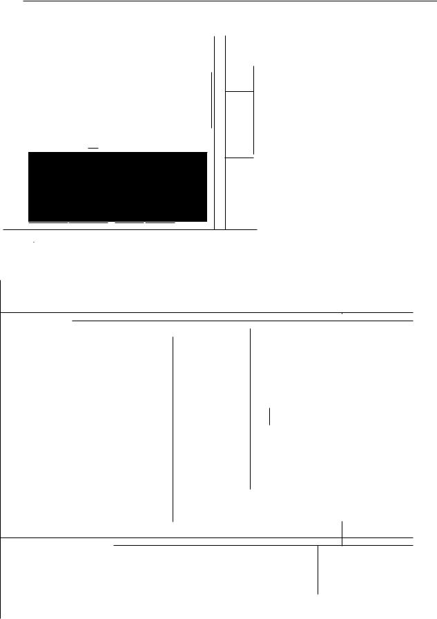
for their exclusive use. Figure 9.3 shows a typical |
|||
ensure that air recycling cannot take place and that the |
|||
arrangement. |
|||
ventilation flow is through the room and across the |
|||
|
|
||
2.4.1 General requirements • |
cells themselves. |
||
Where mechanical ventilation is unavoidable, fans |
|||
Battery rooms are well ventilated and dry, with wall and |
|||
must be acid-resistant, with totally-enclosed motors, |
|||
ceiling finishes durable and free from flaking and corro- |
and installed at the outlet of any ducting which itself |
||
sion. They are generally treated with an acid-resistant |
is made of materials resistant to acid corrosion. It is |
||
paint. This also applies to any metalwork within the |
essential that the ventilation system on the outside of |
||
room. |
such a room is exclusive to the battery room. |
||
Floor finishes are generally antistatic. They are laid |
|
||
level beneath batteries and access areas. Elsewhere they |
2.4.4 Lighting |
||
slope to a drain constructed of acid-resistant materials |
|||
It is normal practice to provide corrosion-resistant |
|||
and/or have a retaining sill across internal door sills. |
|||
The battery room can conveniently house all the |
luminaires in battery rooms. Mounting directly over |
||
maintenance equipment, protective clothing and serv- |
cells is avoided, to prevent accumulation of hydrogen |
||
ices. A water tap and porcelain sink is provided in each |
in the luminaire with consequent risk of explosion. |
||
battery room. |
|
||
|
|
2.4.5 Battery main connections in battery rooms |
|
2.41 Ambient temperature
Since battery capacity and performance is reduced by low temperature, a minimum electrolyte temperature of 5 ° C is maintained as a general rule. However, in nuclear power stations, where reduced capacity could affect the safe shutdown of a reactor, a minimum temperature of 15 ° C is maintained by thermostatically controlled heaters of the totally-enclosed tubular type.
Whilst batteries are capable of operating in an ambient temperature of 35 ° C, with occasional excursions to 40 ° C, these high temperatures are avoided, as they
Connections within the battery rooms and to the outside are made of suitably-sized solid copper rod identified at intervals with acid-resistant red/black paint (or tape) for positive/negative connections, respectively. They are supported on suitable stand-off insulators mounted on battery room walls or on extensions of battery stands. The supports are designed to withstand the electromagnetic forces experienced in the event of an inadvertent short-circuit.
The main connections to the DC switchgear are taken from the battery via through wall bushings to a top-
757

Emergency supply equipment |
Chapter g |
|
ROOF SLOPED TO AID VENTILATION
8,7
BATTERY
SINGLE ROW
DOUBLE TIER
At_
OF DOUBLE ROW DOUBLE TIER STANDS |
BATTERY DOUBLE |
ROW DOUBLE TIER STAND |
1900 MIN
SINK:BENCH
BATTERY ROOM PLAN
FIG. 9.3 Typical layout and environmental requirements of a battery room
VENTILATION AIR
TO ATMOSPHERE //1.-
758
Batteries
WALL BUSHING
—11.1 PITCH
1—T7 M iII IrnmrnmH |
|
THIMJIMMI |
BATTERY Sw1TCHGEAR |
|
\wrinom1-71-7
|
|
-4 |
|
LENGTH = NUMBER OF CELLS X PITCH |
|
|
|
11.1 |
.4— 100 MIN |
|
|
|
|
|
|
|
|
|
|
|
|
|
|
||||||||
|
|
|
|
ELEVATION 'B - El' |
|
|
|
|
|
|
|
|
|
|
|
|
|
|
|
|
|
|
|
||||||||
|
|
|
|
|
|
|
|
|
|
|
|
|
|
|
|
|
|
|
|
|
|
|
|
|
|
|
|
||||
|
|
|
|
|
|
|
|
|
|
|
|
|
|
|
|
|
|
|
|
|
|
|
|
|
|
|
|
|
|
|
|
|
|
|
BATTERY CAPACITY An) |
|
|
|
80 |
|
120 |
|
160 |
200 |
• |
320 |
480 |
|
720 |
• |
880 |
• |
1120 |
|
1360 |
1 600 |
|||||||
|
|
|
AT 3 HOUR RATE AT 20C |
|
|
|
|
|
240 ' |
|
• |
|
|
|
|||||||||||||||||
|
|
|
|
|
|
|
|
|
|
|
|
|
|
|
|
|
|
|
|
|
|
|
|
|
|
|
|
|
|||
|
|
|
BATTERY CAPACITY (AR) |
|
|
|
100 |
|
150 |
|
200 |
250 |
300 |
|
400 |
600 |
|
900 . |
|
1100 |
. |
|
1400 |
|
1 700 |
2000 |
|||||
|
|
|
AT 10 HOUR RATE AT 15:C |
|
|
' |
|
|
|
|
|
: |
|
||||||||||||||||||
|
|
|
|
|
|
|
|
|
|
|
|
|
|
|
|
|
|
|
|
1, |
|
1 |
|
|
|
|
|
||||
|
|
|
|
|
LENGTH |
|
134. |
172 |
|
210 |
248 |
286 |
|
362 |
257 , |
307 |
357 . |
|
433 |
|
509 |
585 |
|||||||||
|
|
CELL |
|
WIDTH |
|
203 1 |
203 |
|
203 |
203 |
203 |
|
203 |
368 |
/ |
368 |
i |
368 |
|
|
368 |
|
368 |
368 |
|||||||
|
|
|
|
|
|
|
|
|
|||||||||||||||||||||||
|
|
|
HEIGHT |
|
423 • |
423 |
|
423 |
423 |
423 |
|
423 |
682 |
|
682 |
|
|
682 |
|
|
682 |
1 |
682 |
682 |
|||||||
|
DIMENSIONS |
|
HEIGHT kg |
186 |
|
249 |
|
306 |
369 |
434 |
|
584 |
106 |
|
156 |
|
|
190 |
|
|
240 |
1 |
290 |
340 |
|||||||
|
|
|
|
|
|
|
|
|
|
|
|
|
|||||||||||||||||||
|
|
|
|
|
' PITCH FACE TO FACE |
140 |
|
178 |
|
216 |
256 |
292 |
|
368 |
|
267 • |
317 |
|
|
367 |
|
|
443 |
|
519 |
595 |
|||||
|
|
|
|
|
PITCH EDGE TO EDGE |
|
|
|
|
|
|
228 |
228 |
|
228 |
|
|
|
|
|
|
|
|
|
193 |
|
393 |
393 |
|||
|
|
|
|
|
FACE TO |
|
|
LENGTH |
1689 |
|
2136 |
|
2592 |
3072 |
3504 |
|
4416 |
|
|
|
|
|
|
|
|
|
|
|
|
|
|
|
|
24 CELLS |
|
FACE |
|
|
WIDTH |
400 |
1 |
400 |
|
400 |
400 |
400 |
|
400 |
|
|
|
|
|
|
|
|
|
|
|
|
|
||
|
SINGLE ROW |
|
EDGE TO |
|
|
LENGTH |
|
|
|
|
|
|
2736 |
2736 |
|
2736 |
|
|
|
|
|
|
|
|
|
|
|
|
|
||
|
DOUBLE TIER |
|
EDGE |
|
|
WIDTH |
|
|
|
|
|
|
407 |
445 |
|
521 |
|
|
|
|
|
|
|
|
|
|
|
|
|
||
|
|
|
|
|
|
|
|
|
|
|
|
|
|
|
|
|
|
|
|
|
|
|
|
|
|
|
|||||
|
|
|
|
|
WEIGHT kg |
447 |
|
598 |
|
735 |
886 |
1042 |
|
1402 |
|
|
|
|
|
|
|
|
|
|
|
|
|
||||
|
|
|
|
|
FACE TO |
|
|
LENGTH |
1860 |
|
2492 |
|
3024 |
3584 |
4088 |
|
5152 |
|
|
I |
|
• |
|
|
|
|
|
|
|
||
|
|
54 CELLS |
|
FACE |
|
|
WIDTH |
680 |
|
680 |
|
680 |
680 |
680 |
|
680 |
|
|
|
|
|
|
|
|
|
|
|
|
|
||
|
DOUBLE ROW |
|
EDGE TO |
|
|
LENGTH |
|
|
|
|
|
|
3192 |
3192 |
|
3192 |
|
' |
|
|
|
|
|
|
|
|
|
|
|
||
|
DOUBLE TIER |
|
|
|
|
|
|
|
|
|
|
|
|
|
|
|
|
|
|
|
|
|
|
||||||||
|
|
EDGE |
|
|
WIDTH |
|
|
|
|
|
|
724 |
832 |
|
954 |
|
|
|
|
|
|
|
|
|
|
|
|
|
|||
|
|
|
|
|
|
|
|
|
|
|
|
|
|
|
|
|
|
|
|
|
|
|
|
|
|
|
|||||
|
|
|
|
|
WEIGHT kg |
1005 |
|
1345 |
|
1653 |
1993 |
2344 |
|
3154 |
|
|
|
|
|
|
|
|
|
|
|
|
|
||||
|
|
|
|
|
FACE TO |
|
|
LENGTH |
1960 |
|
2492 |
|
3024 |
3584 |
4088 |
|
5152 |
|
|
|
|
|
|
|
|
|
|
|
|
|
|
|
105 CELLS |
|
FACE |
|
|
WIDTH |
1970 |
|
1970 |
|
1970 |
1970 |
1970 |
|
1970 |
|
|
|
|
|
|
|
|
|
|
|
|
|
|||
|
2 X DOUBLE ROW |
|
EDGE TO |
|
|
LENGTH |
|
|
|
|
|
|
3192 ' 3192 |
|
3192 |
|
|
|
|
|
|
|
|
|
|
|
|
|
|||
|
DOUBLE TIER |
|
EDGE |
|
|
WIDTH |
|
|
|
|
|
|
2058 |
2274 |
1 |
2518 |
|
|
|
|
|
|
|
|
|
|
|
|
|
||
|
|
|
|
|
WEIGHT kg |
1953 |
|
2615 |
|
3213 |
3875 |
4557 |
|
5132 |
|
|
|
|
|
|
|
|
|
|
|
|
|
||||
|
|
|
|
|
FACE TO |
|
|
LENGTH |
2240 |
|
2648 |
|
3456 I 4096 |
4672 |
|
5888 |
! |
|
|
|
|
|
|
|
|
|
|
|
|||
|
|
125 CELLS |
|
FACE |
|
|
WIDTH |
1970 |
|
1970! |
1970 |
1970 |
19701 |
|
1970 |
|
|
|
|
|
|
|
|
|
|
|
|
|
|||
|
2 X DOUBLE ROW |
|
EDGE TO |
|
|
LENGTH |
|
|
|
|
|
|
3648 |
3648 |
|
3648 I |
|
|
|
|
|
|
|
|
|
|
|
||||
|
DOUBLE TIER |
|
|
|
|
|
|
|
|
|
|
|
|
|
|
|
|
|
|
|
|
|
|||||||||
|
|
EDGE |
|
|
WIDTH |
|
|
|
|
|
|
2058 |
2274 1 2518 |
|
|
I |
|
|
|
|
|
|
|
|
|
|
|||||
|
|
|
|
|
WEIGHT kg |
2325 |
|
3113 |
|
3825 |
4613 |
5425 |
|
7300 |
|
|
|
|
|
|
|
|
|
|
|
|
|
||||
|
—SINGLE ROW |
|
FACE TO FACE |
|
|
|
|
|
|
|
|
|
|
|
370 |
|
370 |
I |
370 |
|
|
370 |
' |
370 |
370 |
||||||
|
ST1LLAGE MOTH |
|
EDGE TO EDGE |
|
|
|
|
|
|
|
|
|
|
|
|
|
|
|
|
|
J |
|
435 |
I |
510 |
585 |
|||||
|
|
|
|
|
FACE TO I |
LENGTH |
|
|
|
|
|
|
|
|
|
|
|
7210 |
I |
8560 |
|
|
9910 |
|
|
11960 |
|
1 4015 |
16055 |
||
|
105 CELLS |
|
FACE |
1 |
WIDTH |
|
|
|
|
|
|
|
|
|
|
|
2390 |
|
2390 |
|
|
2390 |
1 |
|
2390 |
|
2390 |
! 2390 |
|||
|
|
, |
|
|
|
|
|
|
|
|
|
|
|
|
|
|
|
|
|
|
|||||||||||
|
2 X DOUBLE ROW |
|
EDGE TO |
1 |
|
LENGTH |
|
|
|
|
|
|
|
|
|
|
|
|
1 |
|
|
|
|
|
|
10610 |
|
1 0610 |
10610 |
||
|
SINGLE TIER |
|
|
|
|
|
|
|
|
|
|
|
|
|
|
|
|
|
|
|
|
|
|
|
|
|
|
|
|
||
|
|
EDGE |
|
|
WIDTH |
|
|
|
|
|
|
|
|
|
|
|
|
|
|
|
|
|
|
|
2650 |
_. |
2650 |
3250 |
|||
|
|
|
|
|
|
|
|
|
|
|
|
|
|
|
|
|
|
|
|
|
|
|
|
|
|
||||||
|
|
|
|
|
WEIGHT kg |
|
|
|
|
|
|
|
|
|
|
|
11130 |
|
16380 |
|
|
19950 |
I |
25200 |
|
3 0450 |
35700 |
||||
|
|
|
|
|
FACE TO |
|
|
LENGTH |
|
|
|
|
|
|
|
|
|
|
|
I 8550 |
1 |
10150 |
I |
11750 |
|
|
4180 |
|
1 6610 |
19040 |
|
|
|
25 DELLS |
|
FACE |
|
|
WIDTH |
|
|
|
|
|
|
|
|
|
|
2390 ! |
2390 |
|
|
2390 |
|
|
2390 |
|
2390 |
2390 |
|||
|
2 X DC,I,BLE ROW |
|
EDGE TO |
|
|
LENGTH |
|
|
|
|
|
|
|
|
|
|
|
|
|
|
|
|
|
1 |
12580 |
|
1 2580 |
12580 |
|||
|
1 |
NC,LE -7,E, |
|
|
|
|
|
|
|
|
|
|
|
|
|
|
|
|
|
|
|
|
|
||||||||
• |
S |
|
EDGE |
|
|
WIDTH |
|
|
|
|
|
|
|
|
|
|
|
|
1 |
|
|
|
|
|
|
2650 |
|
2950 |
3250 |
||
|
|
|
|
|
|
|
|
|
|
|
|
|
|
|
|
|
|
|
|
|
|
|
|
|
|||||||
|
|
|
|
|
WEIGHT k. |
|
|
|
|
|
|
|
|
|
|
13250 |
! |
19500 |
|
|
23750 |
|
|
30000 |
i |
3 6250 |
. 42500 |
||||
|
|
|
|
|
|
|
|
|
|
|
|
|
|
|
, |
|
|
|
|
||||||||||||
|
|
|
|
|
ALL DIMENSIONS IN mm |
|
|
|
|
|
|
|
|
|
|
|
|
|
|
|
|
|
|
|
|
|
|||||
|
|
|
Hu. |
9.3 coned) Typical layout and environmental requirements of a battery room |
|
|
|
||||||||||||||||||||||||
759
Emergency supply equipment |
Chapter 9 |
|
|
|
|
|
MINma |
|
entry fuse switch unit mounted immediately outside the battery room. Cable connections to the respective chargers or distribution boards are all made at the bottom of these fuse switch units.
2.4.6 Access to battery rooms
Access doors to battery rooms should be locked from the outside of the room at all times, except when work is carried out within the room. Emergency exit doors must be provided with a quick release device on the inside, operative at all times, even when locked from the outside.
To prevent damage to cells, battery rooms must not be used as access routes to other areas.
2.5 Initial tests, charging, maintenance and site testing
The capability of a battery system to meet emergency demands throughout its life depends on the condition and state-of-charge of the battery installation. CEGB guidelines ensure that operators can have confidence in the capability of a battery to meet an emergency demand.
Plante cells basically deliver 100% capacity after initial preparation and charging. Their end of life is not predictable by relating capacity to years of service. They would normally deliver 100% capacity throughout their life which, if they are on charge/discharge cycling operation, can be in the order of 500/600 full cycles. On float charge service, the life is usually dependent on the manner in which the cells are managed. It can be judged from the physical state of the battery, coupled with knowledge of cell electrolyte, specific gravities, voltages and related data. Such data can best be assessed by a specialist from by a manufacturer.
2.5.1 Tests in manufacturer's
Tests on batteries in manufacturer's works can be divided into two categories:
•Type tests.
•Routine tests.
the emergency loads specified for the particular battery, During the discharge, records of voltage, temperature and specific gravity are taken and plotted against time At the end of the discharge, the cell voltage must be such that, for a complete battery of such cells, th e
total voltage must not be less than that specified. The cells used above are then charged at the specified
starting rate to a cell voltage of 2.3 V and from thi s voltage at the specified finishing rate to a cell voltage of 2.7 V. Voltage, temperature and specific gravity are recorded and plotted against time. The time required to charge the battery must not be longer than that spe, cified. Starting and finishing rates are given in Section 2.5.3 of this chapter.
During the foregoing tests the specific gravity must be maintained within specified upper and lower limits. Electrolyte must not be added during discharge. After charging the specific gravity may be adjusted to the specified normal figure.
In order to ensure that the cell lid is correctly bonded to its container, an air leakage test at an appropriate pressure is carried out. No loss of pressure must take place over a specified period.
Routine tests
Apart from a visual examination, the only routine test carried out on each cell in the manufacturer's works is the air leakage test described above.
2.5.2 Tests at site
After erection and initial filling with electrolyte and charging, a discharge test to demonstrate the 3 h rated capacity is carried out on each battery. For this, the manufacturer provides a resistive load frame, as it is unlikely that load is available in the power station at that stage. A discharge characteristic of voltage against ti me is plotted. On completion, the battery is fully
recharged.
Further tests are carried out in conjunction with the associated chargers and are described in Section 4.4.4. of this chapter.
2.5.3 Charging
Float charging
Type tests are usually carried out on a representative sample of cells of a new design and provide a means of proving the design characteristics. Routine tests are less searching in character and are usually confined to establish that a cell has been assembled correctly.
Type tests
Dependent on the total number of cells, one or more cells of each type and size are fully charged. After a period of not less than 12 h and not more than 18 h during which the cells are disconnected from the supply, they are subjected to a discharge appropriate to
The method of operation for all the battery systems is known as 'float charging' which means that the charger, the battery and the DC standing (i.e., continuous) load are all connected in parallel. The charger output voltage is such that the battery voltage is held constant at a voltage of 2.25 V per cell. This is the optimum floating voltage, resulting in the longest possible life allied to the minimum maintenance requirements. Assuming the battery is fully charged to begin with, it will take sufficient 'trickle' charge from the charger at the above voltage to ensure it is maintained in a fully charged condition.
760
|
|
|
Batteries |
|
|
|
|
||
The charger is sufficiently rated to supply the DC |
age is always less than the gassing point of the cell |
|||
otern standing load and recharge the battery. The |
at 2.30 V per cell. Stratification produces a higher |
|||
s |
|
|
||
„'-) l e purpose of the battery, with the charger in service, |
specific gravity at the bottom of the cells than at the |
|||
is to su pply any peak loads such as circuit-breaker |
top because the water in the electrolyte has a tower |
|||
osine solenoids which are in excess of the charger |
density than the acid. This stratification will eventually |
|||
, city. The capacity removed from the battery by |
disappear after about one to two months with con- |
|||
rhese short duration loads is normally replaced by the |
tinual float charge at 2.25 V per cell and the electrolyte |
|||
,;11,1r2er a utomatically. However, emergency or acci- |
will become fully mixed, providing further discharges |
|||
Jental discharge in excess of 5-10% of the 10-hour |
have not taken place. |
|
||
r ated capacity of the battery may over-discharge it; |
A further objection to this method of charging is |
|||
boost charging would then be required. |
the increase in time to achieve a fully charged battery. |
|||
|
|
The following approximate recharge times could be |
||
Boost charging |
expected: |
|
||
|
|
|||
The quickest and best way of recharging a battery after |
Previous discharge, as a |
|
||
a discharge amounting to more than 5-10% of the |
|
|||
percentage of normal |
Recharge time |
|||
10-hour rated capacity of the battery is to raise the |
||||
battery capacity at |
(hours) |
|||
battery cell voltage from its floating value of 2.25 V to |
||||
10-hour rate, % |
|
|||
a maximum of 2.7 V. This is commonly known as 'boost |
|
|||
|
|
|||
c harging'. It involves isolation of the battery and its |
25 |
10 |
||
associated charger from the load, because the voltage |
50 |
24 |
||
imposed on the load may exceed the upper limit of its |
75 |
42 |
||
design voltage. |
100 |
72 |
||
At the commencement of recharge, the charger input |
|
|
||
current to the battery is limited to 14% of its 10-hour |
As the charger automatically maintains the float charge |
|||
capacity, called the starting rate, up to a cell voltage of |
rate at a nominal 2.25 V per cell (see Section 4.2.2 |
|||
2.3 V, i.e., the gassing point. The current is then man- |
of this chapter), the battery would be approximately |
|||
ually reduced to 7% of the 10-hour capacity, called the |
||||
76% recharged in 12.5 hours, but it would take a |
||||
finishing rate, for the remainder of the recharge in order |
||||
considerable time to put back the remaining percentage |
||||
to li mit the amount of gassing from the cell and to pre- |
capacity to restore its full capacity for emergency use, |
|||
, .ent damage to the plates. Charging is continued, taking |
|
|
||
specific gravity and voltage readings, until they become |
2.5.4 Factors affecting cell life and precautions |
|||
sensibly constant over a period of three hours and all |
||||
to be taken |
|
|||
Lens are liberating gas bubbles in similar amounts. The |
|
|||
|
|
|||
system is then returned to normal float charge. |
Loss of active material from the plates due to cyclic |
|||
Boost charging enables a fully discharged battery to |
||||
service |
|
|||
he recharged in 10.5 h, whilst a battery discharged at the |
|
|||
|
|
|||
15-minute rate would be completely recharged in ap- |
Lead-acid cells shed active material in service: when the |
|||
proximately four hours. The length of time taken to |
mud spaces below the plates are full of debris, creating |
|||
recharge a particular battery obviously depends on the |
short-circuit paths between plates, the whole battery |
|||
am pere-hour capacity taken out of the battery during |
should be replaced. A correctly designed battery, when |
|||
the emergency discharge, i.e., the load, the duration and |
on float charge, should be time expired before the |
|||
the final battery voltage at the end of the discharge. |
mud spaces are filled. |
|
||
An important point to note is that a battery can |
With clear transparent cell boxes, it is possible to |
|||
he over-discharged and permanently damaged. The DC |
examine the state of the plates and separators at the |
|||
loads must be disconnected at the end of the design |
edges of the cells and to check the rate of sludge build- |
|||
duty to prevent any possibility of this occurring. Bat- |
up in the mud space. The end of life would usually |
|||
teries must not be discharged past a specific gravity |
occur when either the sludge has built up to the plates |
|||
specified by the manufacturer, typically 1.170. |
in at least one cell or there are other indications of |
|||
|
|
failure. It is usual for cells to be installed in the edge- |
||
Limited voltage recharging |
to-edge orientation, i.e., the plates are at right angles |
|||
Instead of boost charging after an emergency or |
to the lines of cells to facilitate inspection. |
|||
Separator failure could cause partial internal short- |
||||
accidental discharge amounting to more than 5-10% |
||||
circuits: examination of cell electrolyte specific gravity |
||||
e! the 10-hour rated capacity of the battery, it is |
||||
should indicate this. |
|
|||
possible to recharge a battery fully at a limiting volt- |
|
|||
|
|
|||
age of 2.25 V per cell, but this is not ideal and is not |
Corrosion at the acid/air interface |
|
||
r ec ommended. |
|
|||
Recharging under these conditions may produce |
Corrosion of pillars, group bars and risers at the |
|||
stratification of the electrolyte, as the battery cell volt- |
acid/air interface is an indication of age. Great care |
|||
761

--■1111111
Emergency supply equipment |
Chapter 9 |
|
is required when carrying out such examinations, since it is not unknown for the riser to appear normal on visual inspection, but for it to collapse and fail when disturbed.
Corrosion of terminals and connectors
Corrosion of terminals and connectors can occur, but is avoidable since they are accessible for cleaning, inspection, preservation and continuity testing.
Failure of the cell container
Safeguards against such failures are:
•Regular inspection of pillar seals and lid/case seal.
•Administrative control of door locks to reduce the risk of accidental damage, e.g., by battery rooms being used as access routes.
Contamination of electrolyte
Electrolyte consumables, hydrometers, etc., must be subject to quality assurance control. Procedures are specified and care must be taken to adhere to them.
Progressively increasing need for make-up water
A change in the make-up water rate is indicative of a change in cell chemistry and serves as an indicator for detailed examination.
An inspection routine is usually based on the following:
•Daily Check overall battery voltage.
•Weekly Check voltage and specific gravity on se-
lected pilot cells per battery, always using the sam e cells. Electrolyte levels are noted and recorded and topped-up, if necessary. A minimum of two pil ot cells per battery are used dependent on the size of the battery and are evenly spaced throughout th e total number of cells, e.g., 1, 30, 60 and so on.
Check voltage and specific gravity, and visually inspect every cell.
• Annually Employ the services of a specialist to assess battery and experience over the year.
• Six yearly See Section 2.5.7 of this chapter.
2.5.6 CEGB experience
It is CEGB policy to follow a pattern of routine inspection, but the exact routine varies from station to station. Some stations employ manufacturers to assist in the assessment of battery conditions.
Generally, the CEGB has followed the recommendations of the specialists regarding battery replacement and overall experience has shown this to be a conservative policy in that there is no record of a battery failing to fulfil its required duty. Equally, the record of battery life of up to 30 years has been satisfactory.
Degree of undercharging or overcharging
Correct battery voltage is necessary to obtain maximum life from an installation. Chargers are checked regularly to ensure that the correct float voltage is maintained.
Boost charging
The condition at any time and the ultimate life of an emergency supply battery is influenced by its state of maintenance. A boost charge every 2-3 years is usual. The rate and duration of a boost charge follows the particular manufacturer's recommendations. Details of the boost charge schedule are included in the operating instructions.
Duty cycles
The number of charge/discharge cycles in service as ‘vell as the type of duty can determine the ultimate life of a battery installation, which has otherwise been maintained correctly.
2.5.5 Inspection
The state of the battery is a good indicator of general conditions of the DC system and its associated chargers. Regular visual inspections are a reliable guide to battery condition and its ability to perform correctly when called upon in an emergency.
2.5.7 The case for testing
Experience with Plant cell batteries has been sound and it is known that cell capacity does not drop until end of life. Nevertheless, it can be argued that discharge testing to establish the capacity of a battery is a more certain demonstration of its ability to perform satisfactorily. However, testing only demonstrates this at the time of test and at all other times reliance has to be placed on the inspection routines. In view of this, the CEGB does not consider it worthwhile to conduct routine discharge tests, for the sake of the battery alone (see Section 2.5.10 of this chapter for DC system tests).
It is important, therefore, to ensure that the inspection routines previously outlined, are sufficiently rigorous and are capable of accurately determining the state of the battery. This can be attained more positively by removing one or two cells for dismantling, followed by closer inspection of all the parts by a specialist. The CEGB recommends that two sample cells are removed from a battery at six-yearly intervals (or at more frequent intervals, e.g., annually, if the normal inspection shows that unusual deterioration has taken place and that such a check would be prudent). These removed cells will be unserviceable after the inspection and therefore new replacement cells will be required to complete the battery.
762
|
|
|
|
Battery systems |
|
|
|
|
|
||
er removal from the battery, but prior to dis- |
tests of essential battery-backed DC systems. These |
||||
A ft |
r, the removed cells are subjected to a capacity |
tests, which provide a demonstration that the whole |
|||
iiara ii |
i |
DC system operates within design limits and can meet |
|||
ck at the half-hour rate from a fully charged state. |
|||||
l .hhe half-hour rate is used, since it generally approaches |
its performance specification, can also be used to Rive |
||||
'I- , juzv ode for which the battery has been installed. |
back-up information on the condition of the battery. |
||||
01 The above Policy has been agreed with the Nuclear |
The case for testing Plante cells has already been |
||||
111,1allations Inspectorate for all CEGB nuclear power |
discussed in Section 2.5.7 of this chapter, and the point |
||||
|
|
|
|
was made that a test is only a demonstration at the |
|
The points to be examined and the acceptable con- |
ti me of test. Nevertheless, if a system test is to be carried |
||||
Jitions are given in Table 9.1. The conditions in this |
out, it can be used to give support information on the |
||||
|
pplicable to any plate in either of the removed |
Plante cells. It must be emphasised that this is not |
|||
r.ible are a |
an essential test to determine the state of the battery. |
||||
LeHs. |
|
|
|
||
|
|
|
The test procedure outlined in Chapter 1, incorporates |
||
If an adverse condition is identified on one plate |
|||||
I one cell only, then a further examination of the |
three phases: |
||||
o |
|
|
|
|
|
Nutery will be conducted. Only if this additional ex- |
• Phase 1 — initial setting up. |
||||
Jirination shows the adverse condition to be present |
|||||
• Phase 2 — application of emergency load to battery. |
|||||
n other plates, should the action indicated for the |
|||||
oondition in Table 9.1 be followed. |
• Phase 3 — recharge of battery. |
||||
|
|
|
|
||
2.5.8 End of life |
During the test, the battery parameters shown in Table |
||||
%, previously described in Section 2.5.6, the CEGB has |
9.2 are recorded. |
||||
|
|||||
followed a conservative policy on replacement of bat- |
|
||||
teries and has also achieved acceptable battery life. This |
3 Battery systems |
||||
policy is continuing. In addition, the requirement to re- |
|||||
|
|||||
inoe cells ensures that a closer inspection can be given. |
3.1 Introduction |
||||
‘k hen the cells reach the conditions indicating that the |
|||||
battery capacity is likely to fall before the next full |
DC'systems are provided for the following three cate- |
||||
inspection is due, steps are taken to replace the battery. |
|||||
gories of equipment: |
|||||
In general, the practice is to replace the battery when |
|||||
• Essential equipment needing a DC supply during |
|||||
the need for a one-yearly inspection is identified (see |
|||||
normal conditions and also required to operate when |
|||||
Table 9.1) as a result of the procedure outlined in |
|||||
AC supplies have been lost, these two categories |
|||||
Section 2.5.7 above. If conditions prevent this practice |
|||||
include: |
|||||
being followed when an annual inspection is required, |
|||||
|
|||||
hen a discharge test at the load duty cycle may be |
Essential instruments |
||||
performed on the complete battery at not greater than |
Control |
||||
± early intervals, to help to decide whether replace- |
Switchgear closing and tripping |
||||
ment may be deferred for the time being. During the |
Telecommunications |
||||
period between discharge tests, the items checked during |
Protection |
||||
AR annual inspection are rechecked every six months, |
Interlocks |
||||
, inee any deterioration in battery condition could affect |
Alarms. |
||||
lmttery capacity. |
• Standby equipment which only operates when AC |
||||
|
|
|
|
||
2.5.9 Uncharacteristic behaviour of odd cells |
supplies to normal equipment have been lost, this |
||||
category includes: |
|||||
Occasionally, it may be discovered that one or two cells |
Emergency lighting |
||||
|
symptoms that are not typical of all the other |
Emergency oil pumps on main plant including tur- |
|||
,ells in a battery. This uncharacteristic behaviour of |
bine-generators and reactor gas circulators, etc. |
||||
odd cells should not necessarily be taken as an indica- |
|||||
Other miscellaneous emergency drives. |
|||||
tion of the unacceptable condition of the whole battery. |
|||||
|
|||||
These odd cells will be discovered by the inspection |
3.2 Provision of DC systems |
||||
routines. The cells exhibiting non-typical behaviour |
|||||
should be replaced by new cells. The reason for the |
In order to satisfy the categories of equipment listed |
||||
behaviour should be determined to ensure that the |
in the previous subsection, the following DC systems |
||||
'hole battery is not affected. |
are provided. |
||||
2.5.10 System tests of essential battery-backed |
3.2.1 220 V DC systems for switchgear closing |
||||
DC systems |
It is generally not economical to supply closing sole- |
||||
|
|
|
|
||
Chapter 1 sets out a test procedure for periodic system |
noids from a battery shared with other loads, such as |
||||
763

|
|
|
|
TABLE 9.1 |
|
|
|
|
|
|
|
|
Regular examination |
of cells |
|
|
|
|
|
|
|
|
|
|
|
|
|
||
|
|
|
Inspection in |
Inspection in |
Inspection in |
|
Replace |
||
|
Item |
|
6 years |
2 years |
i |
year |
|
battery it |
|
|
|
|
|
|
|
|
|
|
|
I |
Capacity (nominal) |
|
Ci = 1 00u/ii |
C1 - |
1 00% |
(71 |
1 00% |
|
CI < 100% |
|
See Note 1 |
|
|
||||||
|
|
-T |
I |
|
I |
|
|
T |
|
|
|
|
|
|
|
|
|
|
|
2 |
Sludge space a/ii of height to |
|
< 40% |
400/0- 60% |
600/u-80% |
|
> 80 0/G |
||
|
negative plate filled |
|
|
||||||
|
|
|
|
|
|
|
|
|
|
|
|
|
|
|
|
|
|
|
|
3 |
Group bar corrosion |
|
- |
|
|
|
|
|
|
(a) Lug/group bar interface on |
50% |
of conducting |
50-25% |
25-15% |
|
Lug detached |
|||
|
any plate |
|
area of joint still |
|
|
|
|
|
or < 15% |
|
|
|
available |
|
|
|
|
|
|
(b) Group bar/pillar interface on |
75% |
of conducting |
75-60N |
60-50% |
|
Pillar detached |
|||
|
any pillar |
|
area of joint still |
|
|
|
|
|
or < 50% |
|
|
|
available |
|
|
|
|
|
|
|
|
|
|
|
|
|
|
|
|
4 |
Positive plate growth |
|
|
|
|
|
|
• |
Sealing or lid lifted |
(a) |
Width |
5 mm gap to the case |
Between 5-2 111111 gap |
Between 2-1 itun gap |
• Cracked case |
||||
|
|
|
|
|
|
|
|
• |
Plate touching the |
(b) |
Height |
At least a 5 mm gap to |
Between 5-2 rum gap |
Between 2 mm and same |
|
ease sides |
|||
|
|
same level as the |
|
|
level as negative plate |
• |
Plate buckled causing |
||
|
See Note 2 |
negative plate |
|
|
|
|
|
causing short |
|
|
|
|
|
|
|
|
|
|
|
5 |
Potential shorting |
|
|
|
|
|
|
|
|
(a) |
Edge/bottom mossing |
|
None |
None |
Any indication |
|
|
||
|
|
|
|
|
|
|
|
|
Short present |
(b) |
Negative plate expansion |
At least 5 mm gap to |
Between 5 and 2 mm |
Between 2 min and level |
|
|
|||
|
|
the separator edge |
gap to the separator |
with the separator |
|
|
|||
|
|
|
|
edge |
|
|
|
|
|
|
|
|
|
|
|
|
|
|
|
Notes to Table 9.1 |
|
|
|
|
Note I: |
High performance Plante |
Standard Plante |
|
|
7.5 Ah plate C1 -= 0.50C10 |
1 0 Ah plate Ct = 0.37C10 |
|||
25 |
Ali plate Ct |
0.48C 10 |
25/30 Ah Plate CI = 0.34C 1 0 |
|
100 |
Ah plate Cu = 0.44C 1 0 |
45/50 Ah Plate Cu = 0.33C 10 |
||
|
|
|
-2.- |
|
|
|
|
1 0 0 / I 5 0 Alt Plate CI |
0.31C io |
|
|
|
200 Ah Plate C1 |
0.30C 1 0 |
CI is the half-hour discharge rate and C 10 is the ten-hour discharge rate
Note 2: Thickness growth will be detected as a mode of failure under items 3 and 5_
luawd!nba Aiddns Apueblaw]

Battery systems
TABLE 9.2
DC system test procedure
Period |
|
Phase l |
|
Phase 2 |
Phase 3 |
||||
|
|
|
|
|
|
|
|
||
|
|
|
|
|
|
|
|
|
|
— |
|
|
|
|
|
|
|
i |
|
Batten, soliage |
‘ |
|
Every 4- hour |
Every -T |
hour |
||||
|
|
|
|
Every |
4; hour |
Every |
i |
|
|
Battery current |
|
|
— hour |
||||||
|
|
|
|
|
|
2 |
|
||
Ambient temperature |
|
|
At start of Phase 2 |
At start of Phase 3 |
|||||
|
|
|
|
|
|
|
|
||
Pilot cells |
|
I mmediately prior |
|
|
|
|
|
|
|
|
|
|
|
|
|
|
|||
|
to commencement |
|
|
i |
|
i |
|
||
|
|
|
of Phase 2 |
Every |
Every |
hour |
|||
(a) |
Specific gravity |
|
-7- hour |
—,- |
|||||
|
|
|
|
|
|
i |
|
||
|
|
|
|
Every ; hour |
|
hour |
|||
(b) |
Electrolyte temperature |
|
|
Every -7 |
|||||
|
|
|
|
|
|
|
|
||
(c) |
Voltage |
|
|
Every |
!T hour |
Every |
-:1- |
hour |
|
|
|
|
|
|
|
|
|
||
Specific gravity, all cells |
|
|
At or near the end of |
|
|
|
|||
Voltage, all cells |
|
|
Phase |
2, |
if duration |
At end of Phase 3 |
|||
|
|
of the |
phase permits |
|
|
|
|||
|
|
|
|
|
|
|
|||
|
|
|
|
|
|
|
|
|
|
emergency lighting, emergency DC drives, etc., because He solenoid operating range is between +5% and
- 15n of the rated voltage, whereas the voltage range of emergency lighting is ±20% and of motors ± 10% continuous; —20% for 30 minutes. If the whole DC were designed around the closing solenoids, then the battery capacity would need to be considerably
higher, typically twice the capacity without the closing
'solenoids since the designed voltage range would be much less. It is therefore generally more economical
to provide dedicated batteries for switchgear closing
.olenoids.
Since BS5311 gives 220 V and 250 V as preferred soilage ratings of solenoids, the CEGB chose the kisser, permitting 105 cells to be used for the 220 V 'solenoids instead of 120 cells at 250 V.
A dedicated battery for switchgear solenoids also offers a distinct advantage with respect to iblackstare ,apability, i.e., complete loss of AC supplies to the ,hargers as the result of a Grid failure.
Under these conditions, switchgear could be operated
or many hours, or even several days as no standing loads are connected to the battery. A shared batter!, would usually only be designed for a 30-minute capacity.
The system is designed to meet the following criteria:
(a)With the battery on 'float charge', it must be possible to close any two circuit-breakers simultaneously.
(b)With the battery on 'float charge', it must be possible to close up to 100 circuit-breakers each day. There must be sufficient spare capacity in the battery rating to avoid having to boost-charge it to meet this duty.
(c)Following a loss of AC supply to the charger, the battery must be capable of supplying the solenoid of the highest current-rated single 11 kV circuitbreaker continuously for 30 s or two 3.3 kV circuit -
breakers simultaneously at the commencement of battery discharge.
Additionally, it must be capable of closing all other designated circuit-breakers, such as interconnectors and emergency pumps, to shut down the station in a safe manner and to restore the supplies following Grid reconnection. The minimum discharge voltage at the end of this duty must not fall below 199 V at the battery fuse switch terminals.
Following this duty and after restoration of the charger supply, it is assumed that no loads will be connected for 10 hours in order to achieve full readiness to meet duties (a) and (b) above.
It should be noted that this system is not necessary if switchgear closing solenoid mechanisms are replaced by motor-wound spring-charged closing mechanisms. The advantages and disadvantages of this choice are discussed in Chapter 5.
3.2.2 110 V DC systems for switchgear control, protection and interlocks
These systems provide a secure DC supply for essential loads, such as:
•Switchgear and controlgear tripping.
•Switchgear closing, where spring-charged closing mechanisms are used.
•Interlocks and protection.
•Local control equipment and essential instruments.
Each battery is designed to be capable of supplying its designated standing and emergency loads for a discharge period of 30 minutes following complete failure of all incoming AC supplies,
Additionally, each battery is also capable of supplying one-half of its designated standing load for a
765

Emergency supply equipment |
Chapter 9 |
|
discharge period of one hour following loss of a charger. This permits a standby charger to be connected manually.
The minimum discharge voltage at the end of these duties must not fall below 102 V at the battery fuse switch terminals.
3.2.3 4-8 V DC systems for telecommunications, plant control and alarms
These systems provide secure supplies for two distinct categories of equipment:
(a)Telecommunications equipment such as:
•Private automatic exchange (PAX)
•Private automatic branch exchange (PABX)
•Direct wire telephone system (DWTS)
•Radio system controllers
•Control desk telephone equipment
•System operation telecommunications equipment.
(b)DC supplies for essential loads, such as:
•Automatic sequence control equipment
•Alarms and indications at central control room
•Manual control from central control room.
Each battery is designed to be capable of supplying its designated standing and emergency loads for a discharge period of 30 minutes following complete failure of all incoming AC supplies.
Additionally, each battery is also capable of supplying one-half of its designated standing load for a discharge period of one hour following loss of a charger. This permits a standby charger to be connected manually.
The minimum discharge voltage at the end of these duties must not fall below 46 V at the battery fuse switch terminals.
3.2.4 250 V DC systems for emergency lighting and emergency drives
These systems provide secure DC supplies for loads, such as:
•Emergency lighting (DC luminaires).
•Emergency auxiliary drives, such as lubricating oil pumps for turbine-generators, gas circulators, etc.
•Emergency valve operation.
•Fire sirens.
Each battery is capable of supplying the designated total load of all emergency auxiliary drives and the designated total emergency lighting load, excluding plant buildings remote from the main station building, for a discharge period of 30 minutes following complete failure of all
The minimum discharge voltage at the end of the se duties must not fall below approximately 211 V at the battery fuse switch terminals.
In the unlikely event that AC supplies are not restored by means of diesel generators, it is necessary to disconnect loads no longer required to permit the hydrogen-cooled generator emergency seal-oil pump s to continue to operate for a further 1.5 hours.
Sufficient spare capacity is allowed in the rating of the battery to avoid having to boost charge it after a 30-minute discharge period with loads as described above.
3.3 Duplication of battery/charger systems
To allow boost charging and maintenance to be carried out, which requires isolation of the battery/charge r combination from the DC load, they are provided in duplicate with suitable switching facilities at the DC switchboard. These permit the two battery/charger systems to be paralleled before taking one off-load.
3.4 DC system voltage limits
Power station DC systems must be designed to lake account of limits of the load voltage. For good battery operation it is necessary to charge at the float voltage, but it is also necessary to discharge the battery down to a sufficiently low voltage, if the full capacity is to be released from the cells.
In order to ensure that the conditions at the terminals of any DC loads are consistent with the requirements of Chapter 1, the battery parameters as shown in Table 9.3 are used.
TABLE |
9.3 |
|
|
|
DC system voltage limits |
|
|
||
|
|
|
|
|
System nominal voltage, V |
48 |
110 |
220 |
250 |
|
|
|
|
|
No. of lead-acid cells |
24 |
54 |
105 |
125 |
Float charge voltage, V |
54 |
121.5 |
237 |
281.3 |
(2.25 ViceII) |
|
|
|
|
Minimum discharge voltage |
|
|
|
|
at battery equipment |
46 |
102 |
199 |
210.5 |
termination, V |
||||
Off-load boost charge |
65 |
146 |
283 |
337 |
voltage, V (2,7 V/cell) |
|
|
|
|
|
|
|
|
|
4 Chargers
4.1 Introduction
From the remarks made in Section 2.5 of this chapter, it will be evident that a correct charging procedure is most important to ensure satisfactory battery life and performance. Modern charging equipment, using AC supplies, provides safe and flexible control of battery
766