

reading / British practice / Vol D - 1990 (ocr) ELECTRICAL SYSTEM & EQUIPMENT
.pdf
|
|
|
|
|
|
|
Types and performance of motors |
|
|
|
|
||||
|
proci.1 means of providing variable-speed for power |
and a slipring induction motor have been used, parti- |
|||||
|
d on |
uu.siliary drives as a means of saving power. |
cularly in Western Europe, for boiler feed pump drives. |
||||
i |
.cent rapid deirelopment of AC variable-speed |
However, a major disadvantage is the current collec- |
|||||
|
rhe |
r |
|
|
|
|
tion associated with the slipring motor which adversely |
|
|
h.is now reached a stage where the improved |
|||||
|
H |
|
|
riub01 |
and reliability should result in |
affects reliability and increases maintenance. The use |
|
|
|
|
|
|
of cage induction motors up to the limit of forced |
||
|
|
|
|
applicaf ion of such drives for controlling |
|||
|
|
|
|
;•1,v, or speed. Variable-speed using DC |
commutation (about 1.5 MW) in conjunction with one |
||
|
|
|
|
much used in the old days, but fell out |
of the DC-link type converters, and brushless syn- |
||
|
|
H |
I' |
|
power requirements (see |
chronous motors above this 1eel (up to about 20 MW), |
|
|
f. ou r |
li r! the ncreasedi |
|||||
|
|
|
|
o' this chapter). However, with the im- |
avoids these problems. |
||
|
|
Techniques and increase in power ratings of |
All static converters inject harmonics into the power |
||||
|
|
|
|
recent years, the use of AC variable- |
supply system, the amount of which is significantly |
||
|
|
|
rter drives is increasing and is competing |
affected by the type of arrangement used for the recti- |
|||
: |
1 1 of her methods of controlling speed or flow, such |
fier. This arrangement also significantly affects the |
|||||
|
ne or damper control of fans or control valves for |
power factor. The harmonic levels must be acceptable |
|||||
|
fhe! following types of drive are discussed as follows: |
to the power supply system and other connected plant. |
|||||
|
All types of converter also inject harmonics into the |
||||||
|
|
|
|
|
|
|
motor, the extent of which depends on the type and |
• |
|
|
|
|
|
|
design of converter and also the motor leakage re- |
• |
|
|
motor, with slip energy recovery. |
actance. One effect of this is to increase the motor |
|||
|
|
|
|
|
|
losses. |
|
• |
\olL1C ource converter. |
|
|||||
|
|
||||||
•arrent source converter.
•Piii,e-Ni. dth-modulated (PWM) converter.
oltage source inverter, the current source inverter he pulse-width-modulated converter can all be ,: ‘ itieLl as DC-link converters because the AC supply
re,:ified to DC before it is filtered and fed into the
•crier, in which thyristors or transistors are switched
,lientially to generate a variable-frequency supply to
motor.
2.4.1 Cycloconverter
..-.,:l morp,erter converts the mains frequency into
• ...friable frequency directly through a one-step con-
.T , ion process. This is the essential difference from
i%pes of converter described later, where the line first converted to DC and then to variable-
through an inverter. A cycloconverter can be to generate variable-frequency variable-
to drke an induction motor. It can also be used he rotor circuit of a slipring motor for slip-energy as described below. The output frequency is
to approximately 40 070 of its input frequency to an acceptable waveform. The cost and cornof power and control circuits make them un-
iretitke |
with other types of converter drives for |
.tt,:ral applications. However, they have been used for |
|
••. .nertt mill |
and steel mill applications, where the mills |
re directly |
coupled to the motor which is supplied by |
|
|
.ii\% frequency cycloconverter. The cycloconverter has •Li tar been used in CEGB power stations.
2.4.3 Voltage source converter
A voltage source converter feeding an induction motor is shown schematically in Fig 7,4. The required output voltage is achieved by controlling the rectifier and the required frequency by controlling the switching of the inverter thyristors. Auxiliary forced-commutation circuits are required to turn off each inverter thyristor at the end of its conduction period, but these circuits are not described in detail here. Voltage source converters can be used with standard induction motors, although some derating may be necessary due to the effects of harmonics, as mentioned above. An example of the application of a voltage source converter is to be found on the gas circulator drives for AGR nuclear reactors, to provide low speed barring and also a variable-speed facility for reactor depressurised conditions.
2.4.4 Current source converter
A current source converter feeding an induction motor is shown schematically in Fig 7.5. The DC current is controlled by employing a current regulation loop, which in turn controls the voltage from the phasecontrolled rectifier. The thyristors or transistors of the
VARIABLE VOLTAGE
DC. LINK
C
|
CONTROLLED |
IN |
2 4.2 Slip-energy recovery systems |
RECTIFIER |
|
|
|
- ' |
, i' - |
flergy recovery systems, in conjunction with a |
|
|
..locorkerter or one of the DC-link type converters |
FIG. 7.4 Voltage source converter |
|||
|
||||
627

Motors |
Chapter 7 |
|
|
|
|
VARIABLE
VOLTAGE
C LINK
AC
|
|
INVERTER |
|
CONTROLLED |
|||
|
|||
|
RECTHE- |
|
|
|
7.5 Current source converter |
||
inverter steer the current source into the three phases of the motor winding to generate a variable-frequency six-stepped current wave. Because of the large DC link reactor and the controlled-current mode of operation, the converter is inherently rugged and has an ability to recover from malfunction. Since the motor is part of the commutating circuit and commutation depends on the motor subtransient reactance, the converter needs to be matched electrically to the motor. The sudden changes in current which are inherent in the output current waveform result in large transient voltage spikes at the motor terminals
2.4.5 Pulse-width-modulated converter
A pulse-width-modulated converter feeding an induction motor is shown in Fig 7.6. A diode rectifier with a small filter capacitor generates a constant DC link voltage: both the magnitude and frequency of the output voltage are controlled within the inverter. The inverter typically has a similar circuit configuration to that of a six-step voltage source inverter, but has a much more complex switching sequence: in addition, there is usually an auxiliary commutating thyristor associated with each main thyristor. Microprocessors are now being introduced into the control circuits. Rapid thyristor or transistor switching is required, so that each half of the output voltage waveform consists of a number of pulses of equal amplitude. The magnitude of the fundamental output voltage is controlled by variation of the total voltage-time area for a half cycle. By suitably modulating the pulse width, the harmonic content of the output voltage can be reduced to a low level.
For synchronous motors, the inverter is commutated by the motor voltage, which is known as 'machine
CONSTANT VOLTAGE
D.C. LINK
AC
—110-
DIODE |
INVERTER |
RECTIFIER |
|
FIG. 7.6 Pulse-width-modulated converter
commutated', and the relatively expensive forcedmutation equipment necessary for induction m rtotilr; can be eliminated. However, forced commutation has to be provided during the initial starting period, up t o approximately 10N speed, because the voltage obtained from the motor during this period is too low to corn. mutate the inverter. Machine-commutated converters for synchronous machine drives are well established and their previous uses include starting schemes for large hydro-generators, e.g., Dinorwig power station, gas-turbine sets and synchronous compensators at some transmission sub-stations. They have additional merits when used with brushless excitation arrangements on the motor and have been used by some Western European supply companies for variable-speed boiler feed pump and fan drives. The advantages of variable-speed AC converter drives can be summarised as follows:
•High efficiency, which is maintained at reduced powers and speeds.
•Wide speed range (10:1 readily achievable), \kith accurate speed control (1 07o).
•Low starting current (i.e., 1 to 1.5 x full-load current (FLC), compared with 5 to 7 x FLC on cage induction motors) with possible cost savings on the power system due to lower starting current and also to less arduous starting conditions for the motor.
•Regenerative braking can be provided, if necessary.
•Converter equipment can be continuously monitored thus facilitating identification of any faulty equipment or components.
•Reduce space required local to driven equipment, compared with cage induction motors driving through hydraulic couplings.
•Maximum speed is not limited by power system supply frequency, for example, speeds greater than 3000 r/min on 50 Hz supply are possible.
•Relatively easy to convert existing fixed-speed drives or to replace obsolete variable-speed drives. Examples have occurred during refit programmes of fossilfuel power stations.
2.5 DC motors
The main application of DC motors in modern power stations is for standby auxiliaries associated with vital services, such as the lubricating oil system of the turbine-generator unit. Thus, if the AC supply to the station auxiliary system fails completely, the turbinegenerator bearings can be fed by the DC motor-driven lubricating oil pump powered from the station bat - tery. On older power stations, DC motors were often used for variable-speed drives, such as boiler fans, etc. However, with increasing power requirements, which tended to exceed the capacity of commercially available motors, together with the need to improve reliability
628

|
|
|
Design and construction |
|
|
|
|
cc:duce |
maintenance, this type is now seldom used |
vides the location for the stator and rotor assemblies, |
|
|
cooler and bearings. The base has to withstand tor- |
||
ch applications and has been largel y superseded |
|||
for ili |
|
|
|
,. ,ifi a ble-speed AC motors, where such speed control |
sional loads, bending forces in both axes and the weight |
||
required (see Section 2.4 of this chapter). |
of the motor. |
||
The principal CEGB requirements are:
3 Design and construction
3 1 Mechanical construction
p, c onstruction of motors depends on many factors as the manufacturer, type, motor rating and, of
the application. For small motors, the use of ,iluminium is increasing for stator frames, cage rotor ,,i„dirws and even stator winding conductors. For :1 dium and large motors, the stator frames are mostly rabrieated-steel box construction, although cast iron
sc.mnetimes used for medium sizes.
ioure 7.7 illustrates the sectional arrangement of a puJal medium-size horizontal cage-induction motor.
Hie hase is the main constructional member and pro-
•Motor frames, end shields, external end covers, external fan cowls to be constructed of metal and be robust enough to withstand conditions experienced within the power station such as ‘ibration, impact and environmental.
•Glass fibre and plastic components must be of adequate design and robustness to withstand the long term effects of the environmental and operating conditions.
•Duplicate motors and their major components to be interchangeable.
•Motors, including those with pedestal-type bearings, to be designed so they can be moved as an integral unit.
COWS |
." • t |
|
flot.$144 -$.4 -t$ |
|
|
|
|
||||||||||
•tiSint t • |
11' • • MVO) , • 1 1 |
11 •11.191•1 |
|
|
|||||||||||||
|
|
flwiStft'llt 40 ,14411) |
|
|
|
|
|
||||||||||
ttowili• 1144)50 t • •111 |
1 |
■)1+0)( |
|
|
|||||||||||||
.1,1411 |
|
1)111,4110 |
|
|
|
1 |
|
|
|
|
|
||||||
tilsok. |
|
|
|
.1 011, 0104111.101 |
|
|
L |
|
|
||||||||
|
11110,St• |
1 |
|
|
• |
st cc.. MAI • COO |
|
|
|||||||||
. |
|
1•01)iiii • II • 141 |
1 |
|
101 |
• |
0 |
15.1=11 |
11 |
. |
|||||||
|
6) |
0411, |
0411 • $0 |
|
|
||||||||||||
0)010•44•14 • s'•t•011 Otte |
|
||||||||||||||||
|
|
|
|
|
|
|
|
|
|
|
t • |
|
|
|
|
||
Itt•Irt•flitt Stilt* S511155 |
|
|
|
||||||||||||||
tittl}illes••$04 • inl |
•nt io 63 et |
|
|
soot- |
|
|
|
||||||||||
tOttor■ |
•• igewoossoloo bi |
|
|
||||||||||||||
tOtotetsolo |
|
|
|
|
|
|
|
|
|
||||||||
|
|
|
|
|
|
tot•t**tettos• |
|
|
|
|
|||||||
••$••`•• |
|
stelltalltooti |
|
|
|||||||||||||
|
tlIsto'tiot■ ••tt'lltiotOt• |
|
|
|
|
||||||||||||
41111011.1,110111•11tettettOtote . |
|
|
|||||||||||||||
: 0 . |
|
|
|
911111,1100' |
|
|
|
||||||||||
|
1 |
611:0 |
01,0 |
sototetbsowt imminiiiummommi......tm |
|||||||||||||
|
|
|
|
|
|
|
|
||||||||||
|
tr.los6 I ft •11$1,:ts toilet |
|
|
|
|||||||||||||
Ott IS11 ' |
1,0 I VI* • ex% $ |
|
• |
|
- |
||||||||||||
|
|
|
|
|
|
|
|
|
|
|
|
|
|
|
|
|
|
FIG. 7.7 Sectional arrangement of cage induction motor
629
Motors |
Chapter 7 |
|
|
|
|
The construction of stator and rotor cores varies from one manufacturer to another and is also a function of type, size and speed. A common method of construction of stator cores of medium and large motors is to build the laminations on mandrels. The laminations are then N.yelded to a framework to form a stator pack. For rotors running at high speed and for those of large diameter, it may be necessary to shrink the laminations onto the shaft or .shaft spider.
The radial airRap between stator and rotor cores must be of sufficient length to prevent the possibility of rubbing between stator and rotor cores during all conditions of service. This must take into consideration the effects of any shaft deflection due to unbalanced magnetic pull. This conflicts with the need to keep the radial airgap small in order to minimise the magnetising current to obtain an improved electrical performance, particularly power factor, of low speed motors.
3.2 Types of enclosure
The motor enclosure is chosen to give adequate protection to persons against contact with live or moving parts inside the enclosure and to the machine against the ingress of solid foreign bodies. Adequate protection is also required against the harmful ingress of water and other liquids. The most vulnerable part of an electric motor to contamination is the electrical insulation of the windings and electrical terminations and it is important that the correct choice of enclosure is made in order to ensure good reliability. The ingress of coal dust, cement dust, water, steam, oil or other contaminants could cause premature electrical or mechanical failure, or overheating of the motor due to restriction of ventilation circuits.
A primary consideration when choosing an enclosure is to examine the environment and decide whether it is suitably clean and dry for direct cooling, using a ventilated type of machine, or whether there is any risk from airborne dust, water, steam, oil or saline atmosphere, which will require total enclosure of the motor. A significant factor in this choice is capit a l cost, which is usually higher with totally-enclosed type s. Other factors which can influence the choice of e n _ closure are whether the motor is situated indoors, or is outdoors and exposed to the weather. Saline environments, such as those encountered with coastal power stations, are particularly arduous. Site conditions during the construction and commissioning of the power station have also to be taken into account, since the risk is greater, often for long periods of time.
A list of standard machine enclosure types used in CEGB power stations is given in Table 7.2.
The general trend is for the greater use of totally. enclosed type motors and they are invariably used for boiler auxiliaries, due to higher levels of contamination. There is also an increasing tendency to use them on turbine-generator auxiliaries, in view of the risk of contamination from steam, water or oil, or from activation of fire protection equipment. With small power motors up to approximately 10 kW, the technical and economic advantages of ventilated-type motors are so marginal that totally enclosed motors are invariably used. For outdoor applications, totally-enclosed weatherproof motors are used with special features provided, such as bearing seals, gaskets between flanged joints and protective finish to bare metal surfaces, such as shaft extensions, etc. Pipeor duct-ventilated motors have occasionally been used in special applications, such as circulating water pumps. These have advantages, particularly for larger machines, where a source of clean air is readily available (inlet duct), or where the
TABLE 7.2
Typical motor protective enclosures and methods of cooling
|
|
Protective |
Method of |
|
|
enclosure |
cooling |
Description |
|
BS4999, |
BS4999, |
|
|
Part 20. |
Part 21. |
|
|
(IEC34-5) |
(1EC34-6) |
|
|
|
|
Drip-proof, screen protected |
|
IP 22 |
IC 01 |
Totally-enclosed, fan-ventilated |
* |
IP 54 |
IC 01 41 |
Totally-enclosed, closed-air-circuit, air cooled, |
* |
IP 54 |
IC 01 51 |
integral heat exchanger |
|
|
|
Totally-enclosed, closed-air-circuit, air cooled, |
* |
IP 54 |
IC 01 61 |
machine-mounted heat exchanger |
|
|
|
Totally-enclosed, closed-air-circuit, water cooled, |
* |
IP 54 |
IC W37 A81 |
machine-mounted heat exchanger |
|
|
|
Totally-enclosed, closed-air-circuit, water cooled, |
* |
IF 54 |
IC W37 A91 |
separately-mounted heat exchanger |
|
|
|
|
|
|
|
* Motors which are situated outdoors or exposed to the weather are required to have a weather-protected enclosure, IPW 55.
630

|
|
|
|
Design and construction |
|
|
|
|
|||
diccharge of relatively large quantities of hot air could |
parallel air circuits: shaft-mounted fans at each end of |
||||
affect the ambient temperature to the detriment of |
the rotor circulate cooling air towards the centre of the |
||||
ating staff or other plant (outlet duct). However, |
rotor and radially outwards through ducts in the rotor |
||||
r |
|
|
and stator cores. Figure 7.8 shows a section through a |
||
he more usual types of enclosure for circulating water |
|||||
t |
|
|
typical radially-ventilated drip-proof motor. |
||
romp motors are drip-proof screen-protected or totally- |
|||||
xclosed, |
c |
losed-air-circuit, air cooled with an increas- |
With totally-enclosed machines, the variations in |
||
y towards the latter, particularly for coastal |
overall designs are greater but the arrangements of |
||||
w, Rrn deri |
|
||||
sr:Itions due to the risk of saline contamination. |
cooling air flow within the machine are basically simi- |
||||
The twe of enclosure is defined in BS4999, Part 20 |
lar, except that they are arranged for a closed circuit. |
||||
[Ec- 34-5) and contains an international code, con- |
At the small power end of the range, the totally- |
||||
sis[in. of the letters IP followed by two numerals. The |
enclosed motor depends on free convection at its outer |
||||
fii„ / di g it (0 to 5) signifies the degree of protection |
surfaces with or without an internal fan. For larger |
||||
j ,ainst contact by persons with live or moving parts |
motors, both internal and external fans are provided, |
||||
iiiside the enclosure and of machines against ingress of |
with heat transfer taking place through fins provided |
||||
solid foreign bodies. The second digit (0 to 8) signifies |
on the stator frame. This is the well known totally- |
||||
the degree of protection against harmful ingress of |
enclosed fan-ventilated motor. Rigger motors have heat |
||||
water. In general, the higher the number, the higher is |
exchangers built into the stator frame, or more often |
||||
he degree of protection. Table 7.3 lists some typical |
are provided with an integral air-to-air heat exchanger |
||||
motor auxiliary drives for a CEGB power station and |
unit mounted either on the machine or, for the largest |
||||
‘.es the types of enclosure used. |
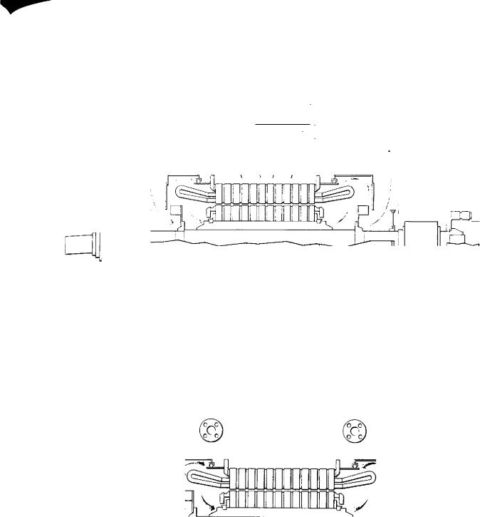
machines, separately mounted. Figure 7.9 shows a |
||||
|
|
|
|
section through a typical closed-air-circuit air cooled |
|
3.3 Methods of cooling |
motor with radial ventilation. |
||||
An alternative to the air-to-air heat exchanger is the |
|||||
With the ventilated types of enclosure, the smaller |
air-to-water type, where water passes through parallel |
||||
,ites of motor are normally provided with axial-type |
rows of cooling tubes and the motor primary cooling |
||||
,entilation, which comprises a single radial fan drawing |
air flows over the tubes. The outsides of the tubes are |
||||
air through axial ducts in the stator and rotor cores |
usually finned to increase the surface area. Figure 7.10 |
||||
(iron laminations), and over the endwindings: it is |
shows a section through a typical closed-air-circuit |
||||
then discharged to atmosphere. For larger machines, |
water cooled motor with radial-type ventilation. |
||||
the cooling surface is increased by using a combination |
For enclosed type motors rated up to approximately |
||||
of axial and radial ducts in the core. The largest |
1500 kW the use of water cooling is generally not |
||||
machines usually have radial-type ventilation with two |
technically or economically preferred and air cooling |
||||
11111111111111111111111
FIG. 7.8 Section of radial ventilated induction motor
631

Motors |
Chapter 7 |
|
|
TABLE 73
Some typical motor auxiliary drives (660 AlW turbine-generators)
|
Auxiliary |
|
Type motor |
Power, |
Speed, |
Voltage, |
Enclosure |
|
Mounting |
|
Number |
|||||||
|
|
kW |
r/min |
V |
|
|
|
per unit |
||||||||||
|
|
|
|
|
|
|
|
|
|
|
|
|
|
|||||
1 |
Turbine-generutor |
|
|
|
|
|
|
|
|
|
|
|
|
|
|
— |
||
|
|
|
|
|
|
|
|
|
|
|
|
|
|
|
||||
|
AC Lub-oil pumps |
|
Sq. cage |
53 |
1450 |
415 |
|
TEFC |
|
>> |
|
|
|
|
||||
|
Standby lub-oil |
, |
|
|
DC |
19 |
1450 |
250 DC |
DPSP |
|
|
|
|
|
||||
|
|
|
|
|
|
|
|
|
||||||||||
|
Jacking oil |
punip |
, |
|
Sq. caee |
36 |
9-10 |
415 |
|
MEC |
|
|
|
|
|
|
||
|
|
|
|
|
|
|
|
|
|
|||||||||
|
Turning gear |
|
|
|
Sq. cage |
50 |
1450 |
415 |
|
TEFC |
|
zz |
|
|
|
|
||
|
Oil purifier |
|
|
|
|
Sq. cage |
11 |
1450 |
415 |
|
TEEC |
|
|
|
|
|
||
|
1-1ydrogen seal oil |
|
|
|
Sq. cage |
15 |
1450 |
415 |
|
TEFC |
|
z |
|
|
|
|
||
|
Standby seal oil |
|
|
|
DC |
15 |
1450 |
250 DC |
TEFC |
|
|
|
|
|
||||
|
|
|
|
|
|
|
|
|
|
|||||||||
|
Stator m.inding liquid |
|
|
37 |
2930 |
415 |
|
TEFC |
|
II |
|
|
|
|
||||
|
pump: — main |
|
|
|
Sq. cage |
|
|
|
|
|
|
|||||||
|
— standby |
|
DC |
37 |
2930 |
250 DC |
TEFC |
|
|
|
|
|
||||||
2 Feed pumps and feed |
|
|
|
|
|
|
|
|
|
|
|
|
|
|
||||
|
heating plant |
|
|
|
|
|
|
|
|
|
|
|
|
|
|
|
|
|
|
Starting/standby |
|
|
|
Sq. cage |
9000 |
1480 |
II 000 |
CACW |
|
I |
|
2 |
x |
50ro |
|||
|
Feed pumps |
|
|
|
|
or slipring |
920 |
990 |
3300 |
CACA |
|
I> |
|
|
|
|
||
|
Feed suction pump |
|
Sq. cage |
|
|
3 |
|
|
||||||||||
|
Condenser extraction pump |
Sq. cage |
920 |
990 |
3300 |
CAC.A |
|
|
3 |
< |
50 0-0 |
|||||||
3 Coat-fired boiler |
|
|
|
|
|
|
|
|
|
|
|
|
|
|
|
|
||
|
I D fans |
|
|
|
|
Sq. cage |
3200 |
590 |
11 000 |
CACA |
|
11111 |
|
2 |
< |
.5 0 1 |
||
|
Sootblower compressor |
|
Sq. cage |
2630 |
1480 |
11 000 |
CACA |
|
|
4, station |
||||||||
|
FD fans |
|
|
|
|
Sq. cage |
2200 |
590 |
11 000 |
CACA |
|
|
|
2 |
|
|
||
|
Pulveriser mills |
|
|
|
Sq. cage |
330 |
980 |
3300 |
CACA |
|
|
|
|
|
10 |
|||
|
PA fans |
|
|
|
|
Sq. cage |
500 |
1480 |
3300 |
CACA |
|
|
|
|
|
10 |
||
4 |
Circulating water pumps |
|
Sq. cage |
3500 |
980 |
11 000 |
DPSP |
|
|
|
4:station |
|||||||
|
CW pumps |
|
|
|
|
|
> |
|
||||||||||
5 |
Reactor — AOR |
|
|
|
|
|
|
|
|
|
|
|
|
|
|
|
|
|
|
Gas circulators |
|
|
|
Sq. cage |
5000 |
2980 or |
ll 000 |
Submerged |
|
I> |
8 |
|
|
8 |
|||
|
|
|
|
|
|
|
|
1470 |
|
|
CO |
2 |
|
|
|
|
||
|
|
|
|
|
|
|
|
|
|
|
|
|
|
|
|
|||
|
|
|
|
|
|
|
|
|
|
|
|
|
|
|
|
|
||
6 |
Reactor — P KR |
|
|
|
|
|
|
|
|
|
|
|
|
|
|
|
|
|
|
Reactor coolant pumps |
|
Sq. cage |
6000 |
1475 |
11 000 |
Special* |
|
|
|
|
|
4 |
|||||
|
|
|
|
|
|
|
|
|
|
|
|
|
||||||
Abbreviations |
TEFC — |
totally-enclosed fan-cooled |
|
CACA |
— |
closed-air-circuit air cooled |
|
|
||||||||||
|
|
DPSP |
drip-proof screen protected |
|
PA |
|
primary air |
|
|
|
|
|
||||||
|
|
I-1 |
|
|
horizontal |
|
|
CW |
— |
circulating water |
|
|
|
|
|
|||
|
|
ID |
|
|
vertical |
|
|
Sq.cage |
|
squirrel cage induction |
|
|
|
|
||||
|
|
|
|
induced draught |
|
|
AGR |
— |
advanced gas cooled reactor |
|
|
|||||||
|
|
FD |
|
|
forced draught |
|
|
PW R |
|
pressurised water reactor |
|
|
|
|
||||
|
|
CACW — |
closed-air-circuit water cooled |
|
|
— |
located inside reactor containment |
|
|
|||||||||
is standard practice. For larger motors up to approximately 5000 kW, both air and water cooling are usually available, but air cooling is preferred unless there is substantial justification for selecting the water cooled type, e.g., overall cost, ambient temperature, etc., since air cooled motors are self-contained and not reliant on an external supply of cooling water. For motors above approximately 5000 kW, the physical size of air-to-air heat exchangers becomes large compared to water cooling, due to the poorer heat transfer properties of air, and for machines of this size water cooling is usually preferred for cost and physical size considerations.
Where water cooling is employed, the coolers are mounted at the side or underneath the motor if p05-
sible in order to minimise the possibility of water contaminating the windings in the event of a leakage. If the cooler is mounted above the motor, spray baffles should be fitted to deflect any leaking water spray away from the windings and towards the bottom of the machine where an alarm should be provided. Catchment trays should also be provided under the cooler stack to contain any leaked water. At coastal power stations, the use of sea water for direct cooling of motors is avoided to eliminate the risk of corrosion and fouling of cooler tubes, towns main water being always used.
The method of cooling is defined in B54999, Part
21 (IEC 34-6) which contains an international code consisting of the letters IC, a group of one letter and
632
Design and construction
|
|
|
|
|
N |
|
|
|
|
|
|
|
|
|
|
|
|
|
I |
|
|
|
|
|
|
|
|
|
|
|
|
|
|
|
|
I |
|
|
|
|
|
|
|
|
|
||||||
|
|
|
|
|
|
|
|
|
|
|
I |
/ |
|||||||||||||
|
|
|
|
|
|
|
|
|
|
|
|
|
|||||||||||||
|
|
|
|
|
|
A |
|
|
|
|
l |
|
|
|
|
|
|
|
|
||||||
|
|
|
|
|
|
|
|
|
|
|
I |
|
/ |
|
|||||||||||
|
|
|
|
|
|
|
|
|
|
||||||||||||||||
|
|
|
|
|
|
|
1 |
|
|
|
|
I |
|
|
|
|
|
|
|
||||||
, |
|
|
|
1 |
|
|
|
|
|
/ |
|
|
|||||||||||||
|
|
|
|
|
|
|
|
|
|
|
|
|
|
|
|
__I |
|
|
|
|
|
|
|
|
|
|
|
|
|
|
|
|
|
|
|
|
|
|
|
|
|
|
|
|
|
|
|
|
|||
|
|
|
|
|
|
|
|
|
|
|
|
|
A |
|
|
|
|
|
|
|
|
||||
|
|
|
|
|
|
|
|
|
|
|
|
|
|
|
|
|
|
/ |
|
|
|||||
|
|
|
|
|
|
|
|
|
|
|
|
|
|
|
|
|
|
|
|
||||||
FIG. 7.9 Section of closed-air-circuit air cooled motor
(5-6 |
6 |
|
|
|
|
|
C |
|
5 0 |
|
|||
|
a |
a |
|
0 |
||
a |
5 |
|
5 a |
a |
a |
|
5 5 |
|
|
|
|||
5 |
5 -5 5 |
|
|
|
|
|
-0 |
|
|
|
|
|
|
,1
r■•■■1.
FtG. 7.10 Section of closed-air-circuit water cooled motor
i■■ 0 numerals for each coolant circuit. The letter |
the coolant. Where there is a primary and secondary |
nifies the nature of the coolant (e.g., A — air, W |
coolant circuit, the secondary is stated first, e.g., IC |
%1. ater), the first numeral (0-9) the means of cir- |
W37 A91 (closed-air-circuit water cooled, with |
, miating the coolant and the second numeral (0-9) the |
machine-mounted cooler). Examples of types common- |
method of supplying the power necessary to circulate |
ly used by the CEGB are given in Table 7.2. |
633

Motors |
Chapter 7 |
|
Separate motor-driven cooling fans are occasionally used for very low-speed motors or for variable-speed motors having a wide speed range. Examples are varia- ble-speed AC commutator motors on older power stations for boiler fan drives.
3.4Windings
Stator windings normally used by the CEGB are:
• |
Random wound (Mush) |
Singleor two-layer lap |
|
|
415 V winding, with circular |
||
|
|
conductors. Considered |
|
|
|
unsuitable for use on |
|
|
|
voltages )3.3 kV. |
|
• |
Diamond windings |
Two-layer lap winding, |
|
|
3.3 kV and above with coils pre-formed |
||
|
|
and insulated prior to |
|
|
|
winding. Open-type |
|
|
|
slots. Used on voltages |
|
|
|
)33 kV. |
|
|
|
Note: |
for the largest |
|
|
motors, half coils may |
|
|
|
be used, with turn-to- |
|
|
|
turn joints made during |
|
|
|
the winding process. |
|
• |
Hairpin (concentric) |
— Single-layer winding. |
|
|
windings — Slot portion and closed |
||
|
|
end of winding pre- |
|
|
|
formed 3.3 kV and |
|
|
|
above and insulated. |
|
|
|
.Open end of winding |
|
|
|
has to be formed and |
|
|
|
individual turn-to-turn |
|
|
|
conductor joints made |
|
|
|
during the winding |
|
|
|
process. Semi-closed |
|
|
|
slots are normally used. |
|
|
|
Note: |
This has now |
|
|
been largely superseded |
|
by the diamond winding, due to cost, ease of repair and high load-losses.
The stator winding and its insulation system is one of the most critical areas of the design. This needs to be of high reliability, of established and proven design, and able to meet the combined effects of:
•Electrical/dielectric stresses.
•Thermal endurance.
•Thermo-cycling.
•Mechanical and thermal stresses.
•Contamination.
• Environmental conditions.
Power station motors are required to have a life endurance of at least 18 000 starts.
Stator windings must be adequately supported, braced and blocked to provide sufficient rigidity during all conditions of service. Special attention needs to be given to the support and bracing system of the stator endwindings of cage induction motors which are t o be direct-on-line started, to cope with the meehani_ cal and thermal stresses produced by the high starting current. The support system for windings of vertical motors must prevent any downward displacement occurring in service. Magnetic slot wedges are generally not so reliable as the non-magnetic type, in that they are liable to delaminate and loosen, so their use is therefore avoided where possible. The electrical joints and connections must withstand the mechanical and thermal stresses involved and should be of brazed or welded construction. Wound rotors for slipring, Ac commutator and DC motors are normally wound two. layer lap or wave, depending on the voltage and current involved. Similar considerations apply as for stator windings, but additionally the windings must be designed to withstand the rotational stresses. The windings are connected to sliprings or commutators.
Cage windings must also be designed to withstand the thermal and mechanical stresses during starting, which can be high, particularly on high inertia drives such as boiler inducedand forced-draught fan drives. Rotor bars must fit tightly in their slots to minimise bar vibration in a radial direction, which could cause premature bar failure. The cage short-circuiting endrings should be of jointless construction in order to avoid the risk of joint failure.
3.5 Insulation systems
The classification of insulation systems is given in BS2757. Insulated windings are Class B or F. Class H is generally only used for applications involving high ambient temperatures such as sootblower motors. Insulation systems must be of proven design and reliability: for voltages of )3.3 kV, they are required by the CEGB to be type-tested.
Further discussion on the performance and test methods of high voltage AC motor insulation is discussed by Schwarz 1969 [5]. The CEGB testing requirements for insulation systems of motors of )3.3 kV are given in ESI 44-5. A summary of these tests follows.
Type tests Intended to evaluate the basic design, materials and manufacturing process of the insulation system. They involve testing at least two sample coils. The tests include:
•Dielectric loss tangent/voltage characteristic of slot
cell insulation and its stability during one thermal cycle of 140 ° C )5 kV.
634

Design and construction
• |
Inter-turn insulation I min, 50 Hz withstand voltage, |
|
also instantaneous 50 Hz withstand voltage. |
||
|
||
|
Slot cell and endwinding insulation 1 min, 50 Hz |
•ithstand voltage, also instantaneous 50 Hz with-
2 e. and Ilat.
quaiity control tests durin2 manufacture in-
DIelectric foss tangent/ voltage characteristics at
• r00'1 temperature ?..5 kV. Test requirements depend on the type of insulation system, i.e., resin-rich or \-acuum/pressure impregnated (VP F), and also on voltage, polarity and kW output of motor.
•In ter-turn insulation — a high frequency impulse ,oltage is injected to the leads of each coil, the
peak voltage being U peak = 3 U il sh/s/3, where U, Is he rated line-to-line voltage.
•Complete winding — I min, 50 Hz overvoltage test to BS4999, Part 60.
The insulation systems of stator windings are specified , 0 he of the epoxy type, with thermosetting materials, mili N,sith the main slot cell insulation based essentially oil mica. The conductor and enclwinding insulation of \sindings ?..6.6 kV should also be based on mica. The anis adjacent to the ends of the slots on such windings Jr,: treated to provide electric stress control, usually hv a semi-conductive tape or semi-conductive varnish. The slot portions of the coils are treated to prevent corona discharge, usually by means of an outer layer of conducting tape.
The windings must be impregnated and suitably pro-
• to seal them effectively to prevent deterioration Cron] adverse environmental conditions at site. Two ,Ii•ulation systems are in general use for windings at -!3,3 kV:
• |
The resin-rich system Coils are insulated with tapes |
|
heasily loaded with uncured resin, usually referred |
|
to as B-stage resin. The coils are then cured by heat- |
|
inu and pressing individually in moulds, or some- |
|
ti mes (for smaller machines) after winding into the |
|
stator core. Figure 7.11 shows details of an II kV |
|
diamond-type coil, including slot configuration. |
• |
Vacuum/pressure impregnation (VPI) The stator is |
|
wound with coils, which are insulated with dry semi- |
|
porous tapes: the winding is then vacuum dried, |
|
Impregnated under pressure and cured by heating. |
Ihe resin-rich system has been used in the UK for many years, but is tending to be superseded by the Pl system which has been extensively used in the
LSand other countries for several years, with much 'th:CeSS. This is mainly due to the better quality control
possible during manufacture and the achievement of %old-free windings.
SECTION SHOWING
TYPICAL SLOT
CONFIGURATION
2 TURN COIL.
2 CONO TURN
Fro. 7.11 II kV diamond-type coil
3.6 Bearings
Bearings can broadly be divided into two main types:
rolling element bearings (sometimes referred to as frictionless bearings) and plain bearings. These can
take various forms, depending on the rated power and speed, whether the shaft is vertical or horizontal, and also on the radial and axial loadings.
Rolling bearings take the form of balls, cylindrical rollers, tapered or spherical rollers. They depend for their satisfactory operation on the clearance between the rolling elements and their races, sometimes referred to as the diametral bearing clearance. Grease is gen-
635

Motors |
Chapter 7 |
|
orally used as a lubricant, but for certain designs or applications oil is occasionally used. Lithium-based creases have replaced soda-based greases for power station motors, due to their stability at higher ternperatures and improved lubricating properties. The construction of the bearing assembly should be such that the bearings can be dismantled without risk of damage. Split-type roller bearings have been used to
'acil tote maintenance on some large motors, |
e.g., cir- |
culating water pumps. Precautions need [ 0 |
be taken |
against the effects of any vibration which could be transmitted when the motor is not running, for example, standby motors. Pre-loaded ball bearings are often used for these applications. Alternatively, plain bearings are used, since these are inherently less prone to damage from such effects. Figure 7.12 shows a typical arrangement of a crease lubricated rolling bearing.
Within the size range in which they are used (see Table 7.4), rolling bearings have the following advantages:
•Low cost.
•Replacement bearings usually readily available.
•Grease lubricant gives good protection against ingress of moisture and dirt into motor.
•Easier to seal against leakage of grease into motor, as compared with oil.
•Low friction torque at starting.
The larger power motors use plain bearings, which may be of the sleeve or tilting-pad type. Oil lubricated bearings may be self-lubricated by means of oil rings, or by a disc running in an oil reservoir. Where forcedoil lubrication is required (for example, in the case of high speeds of 3000 r/min or high bearing loads), the oil pump is driven from the main shaft system and is self-priming. Where possible, such a lubricating system is made common to the motor and its driven auxiliary.
Tilling-pad bearings are used where appreciable axial thrusts are present, for example, in vertical motors for circulating water pumps. Lubrication must be adequate during starting, particularly of standby equipment with automatic start, and also during running-down if this
TABLE •.4
Type of motor bearing
Synchronous speed — rim n |
Rating |
Type of |
|
bearing |
|||
|
|
||
|
|
|
|
1000 and below |
Up to 750 kW |
Rolling |
|
1000 and below |
Above 750 kW |
Plain |
|
Above 1000, up to 1500 |
Up to 530 kW |
Rolling |
|
Above 1000, up to 1500 |
Above 530 kW |
Plain |
|
Above 1500 |
Up to 375 kW |
Rolling |
|
Above 1500 |
Above 37$ kW |
Plain |
|
|
|
|
Fin. 7.12 Typical arrangement of a grease lubricated rolling-type bearing
is of long duration, such as can occur on high-inertia loads. A motor-driven oil pump may additionally be fitted in such cases. A motor-driven jacking oil pumP may be needed for starting drives with heavy shaft loads. Figure 7.13 shows a typical arrangement of an oil lubricated sleeve-type bearing.
For motors above 750 kW, it is the practice for bearings of the motor and its driven auxiliary to be
636