

reading / British practice / Vol D - 1990 (ocr) ELECTRICAL SYSTEM & EQUIPMENT
.pdf
|
tot |
a |
corner CO |
uctor add 30%, therefore V L |
|
|
|
||||
= |
|
|
d for a central conductor subtract 30%, |
||
LV an |
63 kV. |
||||
|
|
|
|
||
|
Tk rig !tw dieiecuic strength of air as 500 kV/m, |
||||
|
|
|
|
not |
occur unless the panel is with- |
, |
:14 min of a corner downconductor or within |
||||
|
|
o t' |
a central |
downconductor. In fact the di- |
|
|
,irenfth of concrete is si milar to air, so these |
||||
-can be assumed to apply to air, concrete
|
|
inirture of [hese mediums. |
|
|
H, method of calculating inductive voltages, by |
|
|
all central or all corner downconductors carry |
• |
|
,.. urrent, is not considered rigorous when applied |
'Ar:le steel or reinforced concrete framed buildings. |
||
I L i: . is because the downconductors are connected |
||
|
'I |
orizontal conductors which themselves have im_ |
|
and therefore the downconductors nearest the |
|
|
|
|
,•r:ke point will carry a higher proportion of current. nerc the building structure itself is used as a down-
n,Meior, there will be a number of vertical paths
.,rmei.1 by the columns interconnected at each floor
c cI as |
a result of the horizontal paths formed by |
|
Figure 6.149 shows the most significant current |
j r, a steel or reinforced concrete framed building |
|
,irike on one corner. As can be seen, the current |
|
•!: ■ :Jcs |
at each building node so that better current |
ring |
is achieved at lower building levels. It should |
.: ) be noted that currents are generally greater in |
|
; m[plieral than in interior conductors. |
|
[ he method given in I3S5651 for dealing with mul- |
|
. dov,nconductors is regarded as adequate for
..,:neral use. However, for special cases, such as when equipment is located at high level in a build- a more rigorous calculation should be carried
N:1
F 1 (.. |
6. |
[49 Distribution of most significant current |
|
paths |
in |
||
a steel or reinforced concrete framed building |
|||
|
|
Lightning protection
Having explored the methods of calculating induc- tively-generated voltages and typical values, it is now necessary to consider what precautions are necessary against the risk of sideflashing. In general there are two solutions, either to ensure there is sufficient distance between plant and downconductors to prevent sideflashing or to bond the plant to the downconductor. In practice, power station buildings tend to be large in size and as a consequence they require many downconductors. The calculated inductive voltages are therefore relatively small as demonstrated in the last calculated example for a building with twelve downconductors. In that example, the clearances required to prevent sideflashing were less than 250 mm for a corner downconductor and less than 150 mm for a central downconductor. This indicates that as a general policy, bonding of plant to downconductors should not be necessary if the following rules are observed:
•Bond reinforcement or steelwork across expansion joints and the like at all floor levels to achieve optimum current sharing.
•Where practical, sensitive electronic equipment should be located at low level in the building.
•No equipment should be mounted on or very close to outside columns or steel reinforced walls.
Quite clearly it is not practical to calculate sideflash distances for all the vast amount of plant within a power station, and it is suggested that if the above rules are followed this is not necessary other than in special cases. An example of a special case is nuclear safety equipment.
12.6 Inspection, testing and records
A log book should be employed to record the results of all visual inspections and resistance measurements.
All lightning protection systems should be visually inspected during installation and after completion to check compliance with BS6651: 1985. All accessible components of the system should be visually inspected at intervals not exceeding 12 months.
Upon completion of the installation, each lightning protection earth electrode should have its resistance measured to demonstrate that it does not exceed 10
as required by 8S6651: 1985. The method of testing should be as given in CP1013: 1965. Tests to measure earth resistance need to be repeated at regular intervals. Because the lightning protection system is bonded to the station earth network which is a high integrity system, it is not considered necessary to carry out these tests at 12 month intervals as suggested in BS665I: 1985. It is therefore recommended that lightning protection earth electrodes be tested at the same frequency as the station earth electrodes which is every 6 years.
687
Cabling |
Chapter 6 |
|
|
|
|
13 Lighting, heating and small power systems
13.1Introduction
Lighting is both an art and a science. It can be both decorative and functional although the balance between decoration and Iiiih:tion will vary with application. The applications considered in a power station are essentially functional. The function of the lighting system in a power station is to provide adequate illumination for safe plant operation and personnel movement. The li ghting system should also contribute to achieving an acceptable overall environment of the work area.
One of the most fundamental decisions to be made when designing the lighting of any interior is the relationship between daylight and artificial (electric) light. This can take three forms:
•Rely on daylight during the daytime and design electric lighting only for night-time conditions.
•Use daylight as available but supplement it as required by electric lighting.
•To ignore daylight and operate by using electric lighting only.
Artificial light is necessary in a power station for two main reasons. The first, quite simply, is that the operation of a power station is a continuous 24-hour per day process and the after dark activities must be catered for; the second reason is that the architecture of the plant and buildings of a power station make it uneconomic and invariably impossible to illuminate adequately with natural daylight.
13.2 Lighting system design
Lighting design is a complex process and no hard and fast rules can be devised which will suit all applications or every designer. The Chartered Institute of Building Services (GIBS) Code for Interior Lighting (1984) offers a design approach that represents reasonable practice and is used by the CEGB as a guide to plan and calculate the lighting requirements for power stations. The recommendations given in this code, and previous issues, reflect and are written confirmation of the good design practice that has been adopted by the CEGB for a considerable number of years in the design of power station lighting systems.
The overall design process proposed by the CIBS code consists of five stages:
• Objectives Determine the objectives of the design in terms of the safety requirements, task requirements and the appearance required.
• Specification Specify the design objectives as a set of compatible design criteria, acknowledging those objectives which cannot be quantified.
To resolve the type of lighting system which will achieve the desired objectives.
Planning of the final sche me using accurate data to ensure the most economi ca l and efficient final design.
• Appraisal The installation is reviewed after corn. pletion in order to assess its success in terms of the design objectives and its acceptability to the us ers (in the case of the CEGB, the power station operating staff).
The following sections consider the application of the above design process to the design of power station main AC lighting systems. The procedure is equally valid for the design of emergency lighting systems, which are discussed in Section 13.3 of this chapter.
13.2.1 Objectives
The design of the lighting system for a power station must meet the specified standard service illuminance and the essential requirement of high reliability, whilst si multaneously satisfying economic requirements m terms of low capital, energy and maintenance costs over the design life of the installation. Due regaid must also be paid to the desirability of minimising the number of different light sources stored as spares by the power station.
Some, if not all, of the above objectives are common to all installations whether in power stations, industrial or commercial premises. One area unique to power stations is the design life of the installation. All installations in power stations are designed for a minimum life of 25 years. The tendency now with modern nuclear stations (e.g., Sizewell B (PWR) power station) is to design for an extended life of 40 years. The lighting equipment manufacturers must present data in support of their claims for the life of their equipment. This must be borne in mind when considering, in addition to the energy and maintenance costs, the ease of replacement and refurbishment of equipment over the design life of the station.
An additional requirement placed on the lighting installations of modern nuclear power stations is the support of the safety-related equipment which has nuclear safety duties. Although the lighting installation is not directly safety-related it is designed to aid the satisfactory supervision of this essential safety-related equipment. Particular attention is therefore given to the main and emergency operation lighting systems in areas of the station containing such equipment, or equipment required to be operated following a trip of the nuclear reactor.
It is also important when considering objectives to establish the design constraints. There are many con - straints which affect the design objectives, such as en - vironmental considerations (which may limit the range of acceptable luminaires) and the physical problems of access.
588

|
|
|
|
|
|
Lighting, heating and small power systems |
|
|
|
|
|
|
|
|
|
13.2,2 Specification |
design process for a power station means that this |
||||||
information is often not available at the required |
|||||||
|
|
|
|
defined the objectives for the main AC in- |
|||
|
|
|
|
ti me. The inflexibility of this system of lighting, where |
|||
|
|
|
|
n, these inti.r be expressed in the form of a |
|||
, |
,; |
i |
changes to the equipment layout can seriously impair |
||||
|
|
ILc o |
:Tecification giving, wherever possible, mea- |
the efficiency of the lighting, make it unsuitable for |
|||
|
|
|
|
mt i t e s wig., the standard service illumi- |
|||
|
|
|
|
use in the major plant areas of power stations but |
|||
|
|
|
|
en in CLGB, GDCD Standard 31). Where |
it is employed in certain other areas. Power station |
||
|
|
|
|
annot be expressed as measurable quanti- |
|||
|
|
|
|
control rooms over the last decade, for example, have |
|||
|
.., ihe lighting designer must exercise experience and |
||||||
|
utilised contoured lighting schemes to illuminate the |
||||||
|
.,!:cinent to replace calculation. It is important that |
||||||
|
control surfaces of the control desks and the fronts of |
||||||
|
|
|
„hiceti%es which cannot be quantified are not over- |
||||
|
|
|
control panels, allowing 'light spill' to illuminate other |
||||
|
|
|
|
|
|
||
|
|
|
|
|
|
areas of the control room floor for access purposes. |
|
|
|
|
|
|
|
Local lighting provides illumination only over the |
|
13 2.3 General planning |
small area occupied by the task and its immediate |
||||||
Mien the design specification has been established, |
surroundings. It is normally associated with a general |
||||||
|
|
|
purpose of the remaining stages of design is to |
lighting system which provides sufficient ambient illu- |
|||
-.instate these physical requirements into the best pos- |
mination for staff movement and the performance of |
||||||
other minor and incidental tasks in the area. This |
|||||||
.11 |
, 1e solutions. There are no hard and fast rules about |
||||||
|
to plan a lighting installation. Experience and |
lighting system is also employed in power stations for |
|||||
|
|
|
|||||
i.,: |
ement will usually dominate the planning process. |
workshops, crane lighting and other areas where high |
|||||
illuminances are necessary for the task to be under- |
|||||||
|
he planning stages can be divided into general and |
||||||
|
|
|
iled planning. |
taken. Local lighting is frequently provided by lumi- |
|||
|
|
|
naires mounted on the work station. An example is |
||||
|
|
the first stage in the general planning of a lighting |
|||||
.r-da/lation is to consider the interior to be lit, its |
the crane lighting which, by means of tungsten halogen |
||||||
rroportions, its contents, and most importantly the |
lamps in flood lantern luminaires mounted on the |
||||||
::• re of lighting to be adopted. |
crane, provides instantaneous lighting of the working |
||||||
surface. |
|||||||
|
|
|
lectric lighting systems fall into three basic |
||||
|
|
|
|
|
|
The designer will consider all three lighting systems |
|
• |
|
General lighting. |
(general, localised and local) when planning the lighting |
||||
|
of a power station, and will to some extent utilise all |
||||||
• |
|
I ocalised lighting. |
three systems to provide the most efficient lighting |
||||
• |
|
local lighting. |
arrangement for the diversity of tasks and buildings. |
||||
|
One objective that must be considered at the gen- |
||||||
|
|
|
|
|
|
||
I i:htin ,7 systems which provide an approximately |
eral planning stage is the desirability of minimising |
||||||
the number of different light sources that need to be |
|||||||
ii niform distribution of light over the entire working |
stored. The choice of lamp will affect the range of |
||||||
:'line are called general lighting systems. The lumi- |
luminaires available and vice-versa. There is a consi- |
||||||
|
|
|
are normally arranged in a regular layout. The |
derable variety of lamps available to the designer, from |
|||
ii rrearance of this type of installation is usually tidy |
tungsten to gas discharge lamps (including the very |
||||||
Hi may be regarded as being rather bland. General |
versatile and efficient tubular fluorescent). The require- |
||||||
:;.21iti lig. is si mple to plan and requires no co-ordination |
ments for lamps are specified in GDCD Standard 32. |
||||||
|
|
|
task locations. The greatest advantage of such |
The advantages and disadvantages of lamps used for |
|||
—reins is that they permit complete flexibility of task |
lighting power station interiors are summarised in |
||||||
io,ation. For this reason, general lighting systems are |
Appendix J. |
||||||
iiredorninantly used for lighting the major plant areas |
When selecting a range of suitable lamps, the de- |
||||||
.11 rower stations. The disadvantages of bland appear- |
signer must consider the types of luminaires which are |
||||||
he |
|
and increased energy requirement to illuminate |
available and the degree of light control and light |
||||
|
\Ode area to the same illumination level are |
output required. |
|||||
Lii%%eighed by the functional requirement for a flexible |
In the choice of luminaire the designer can exer- |
||||||
ii ;hting system throughout the life of the power station. |
cise a combination of professional judgement, personal |
||||||
•Localised lighting systems employ an arrangement |
preference and economic analysis. Luminaires in a |
||||||
it luminaires designed to provide the required service |
power station have to withstand a variety of physical |
||||||
wurninance on the work areas together with a lower |
conditions, such as vibration, moisture, dust, ambient |
||||||
Illuminance for the other areas provided by 'light spill'. |
temperature, general ill-treatment (including theft), |
||||||
IThe layout of localised lighting must be co-ordinated |
etc. The onus is on the designer to specify safe equip- |
||||||
%s |
|
|
|
|
|
ment. CEGB Standards have been produced to as- |
|
al) the equipment and task positions. The system can |
|||||||
be inflexible and it is essential that correct information |
sist the designer in specifying the required standard |
||||||
fl |
|
.equipment and task locations is available at the |
of equipment. These are GDCD Standards 35, 36 |
||||
design stage. The magnitude and complexity of the |
and 37. |
||||||
589
Cabling |
Chapter 6 |
|
Specialised luminaires are also required for power stations to warn aircraft or shipping, or to light hostile and hazardous environments. These luminaires are discussed in Section 13.4 of this chapter.
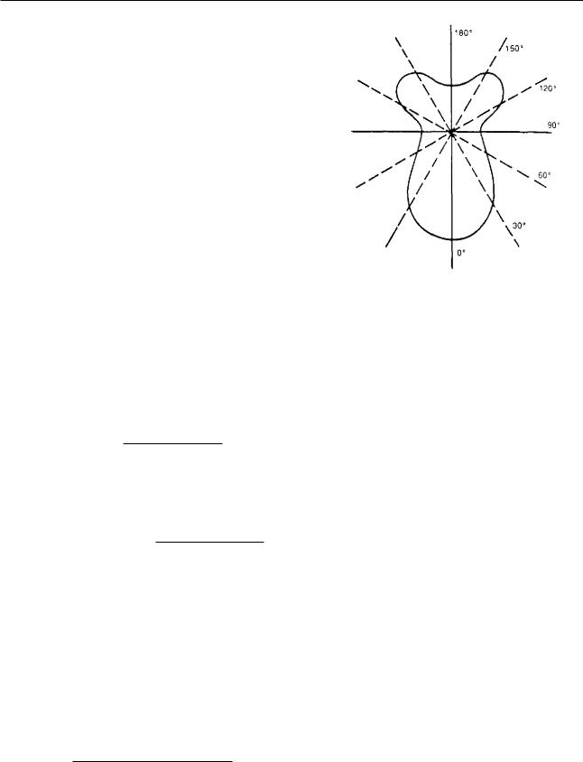
Luminaires may be classified in a number of ways, the most important being on the basis of their light distribution since this influences the distribution of illuminance and the directional effects that will be achieved. The luminous intensity distribution (or light distribution) from a source is usually shown graphically in a polar curve, see Fig 6.150. The curve is produced by plotting the luminous intensity in a series of directions within one vertical plane through the source, and defines the way in which the luminaire controls the light from the lamp.
The first way to classify the luminaire from its light distribution is in terms of the proportion of the total light output of the luminaire in the upper and lower
hemispheres of the polar curve. A luminaire giving all or very nearly all of its light downwards is called direct, and one giving all light upwards indirect. Between these
two extremes the intermediate types are called semidirect and semi-indirect.
The fractions of upwards and downwards light ex-
pressed as percentages of the total light from the luminaire are termed the flux fractions. The flux fraction ratio may also be quoted, although this may be cal-
culated from the flux fractions, i.e.,
Upper flux fraction
Flux fraction ratio
Lower flux fraction
The ratio of the luminous flux from the luminaire to that from the lamp is called the light output ratio (LOR).
Light from luminaire
Light output ratio, LOR —
Light from lamp
The light from the luminaire is the sum of the upwards and downwards light from the luminaire. It is also possible to express the light output ratio in terms of its upwards and downwards components:
Upward light output ratio, ULOR
Upward light from luminaire
Light from lamp
Downwa.rd light output ratio, DLOR
Downward light from luminaire
Light from lamp
The light output ratios and flux fractions are important to the designer because they are involved in assessing the level of glare associated with a luminaire.
The second way of classifying luminaires according to their light distribution is the British Zonal (BZ)
Flu. 6.150 Example of polar curve
classification. This is a procedure whereby the curve of direct ratio (the proportion of downward light from the fitting that is directly incident on the working plane) against room index for an actual luminaire is compared with a family of ten hypothetical curves which cover the whole range of possible downward concentrations, ranging from the most concentrated to the most widely dispersed (see Fig 6.151). The room index is a measure of the proportions of the room; the area, perimeter and height of the fittings. The area between the curves is termed a zone. From the hypothetical curves a family of ten standard zones results, identified by the numbers 1 to 10. The curve of the actual luminaire will lie within one of these zones and the luminaire will then be classified and assigned a BZ number, e.g., BZ5 means . the curve lies within zone number 5.
Manufacturers of luminaires will provide the following information on their luminaires:
•British Zonal (BZ) classification.
•Upward light output ratio.
•Downward light output ratio.
•Luminous area.
The luminous area is the area of the luminous part of the luminaire as seen from vertically beneath it.
The manufacturers may also quote the upper and lower flux fractions or flux fraction ratio, though these may be calculated from the output ratios. These characteristics of the luminaire enable the designer CO determine at the general planning stage the glare indices, the acceptable luminaires and surface reflectances, and the utilisation factor.
Glare occurs whenever one part of an interior is much brighter than the general brightness in the interior-
590

Lighting, heating and small power systems
|
|
|
|
|
|
|
|
|
|
|
|
|
|
|
|
affect it, the brightness of the source (BO, |
the bright- |
||||||
|
|
|
|
|
|
|
|
|
|
|
|
|
|
|
|
ness of the background (Bb), the apparent |
|
size of |
|||||
|
|
|
|
|
|
|
|
|
|
|
|
|
|
|
BZ |
the source (a solid angle co) and the position of |
the |
||||||
|
|
|
|
|
|
|
|
|
|
|
|
|
|
|
source in relation to the direction in which |
the eyes |
|||||||
|
|
|
|
|
|
|
|
|
|
|
|
|
|
|
|
||||||||
|
|
|
|
|
|
|
|
|
|
|
|
2 |
are looking (represented by an index, p). |
|
|
|
|
|
|
||||
|
|
|
|
|
|
|
|
|
|
|
|
3 |
The relationship between the direct glare index |
and |
|||||||||
|
|
|
|
|
|
|
|
|
|
|
|
|
|
|
|
||||||||
|
|
|
|
|
|
|
|
|
|
|
|
|
|
|
|
these factors is: |
|
|
|
|
|
|
|
|
|
|
|
|
|
|
|
|
|
|
|
|
|
|
|
Glare index = |
|
|
|
|
|
|
|
|
|
|
|
|
|
|
|
|
|
|
|
|
|
|
|
w )0.8 |
|
|
|
|
|
|
|
|
|
|
|
|
|
|
|
|
|
|
|
|
|
|
|
|
|
|
|
|
|
||
|
|
|
|
|
|
|
|
|
|
|
|
|
|
|
|
10 logio[ 0.5 x constant E B s" |
X |
|
1.6 |
|
|
||
|
|
|
|
|
|
|
|
|
|
|
|
8 |
Bb |
|
|
P |
|
|
|
||||
|
|
|
|
|
|
|
|
|
|
|
|
|
|
|
|
|
|||||||
|
|
|
|
|
|
|
|
|
|
|
|
1 0 |
The implementation of the IES glare index system is |
||||||||||
|
|
|
|
|
|
|
|
|
|
|
|
|
|
|
|
fully discussed in specialist design manuals such as the |
|||||||
|
|
|
|
|
|
|
|
|
|
|
|
|
|
|
|
Electricity Council's Interior Lighting Design Manual |
|||||||
|
|
|
|
|
|
|
|
|
|
|
|
|
|
|
|
and the CIBS Code for Interior Lighting. |
|
|
|
|
|
|
|
|
|
|
|
|
|
|
|
|
|
|
|
|
|
|
|
The utilisation factor (UF) for a luminaire |
is a |
||||||
|
|
|
|
|
|
|
|
|
|
|
|
|
|
|
|
measure of the efficiency with which light from |
|
the |
|||||
|
|
|
|
|
|
|
|
|
|
|
|
|
|
|
|
lamp is used for illuminating the working plane, i.e., |
|||||||
|
|
|
|
|
|
|
|
|
|
|
|
|
|
|
|
the luminous flux which reaches the working plane |
|||||||
|
|
|
|
|
|
|
|
|
|
|
|
|
|
|
|
expressed as a ratio of the luminous flux emitted by |
|||||||
|
|
|
|
|
|
|
|
|
|
|
|
|
|
|
|
the lamp. |
|
|
|
|
|
|
|
|
|
|
|
|
|
|
|
|
|
|
|
|
|
|
|
Although utilisation factors can be calculated by the |
|||||||
|
|
|
|
|
|
|
|
|
|
|
|
|
|
|
|
designer (refer to CIBS Technical Memorandum No 5), |
|||||||
|
|
|
|
|
|
|
|
|
|
|
|
|
|
|
|
most manufacturers publish UFs for standard condi- |
|||||||
|
|
|
|
|
|
|
|
|
|
|
|
|
|
|
|
tions for their luminaires. It should be noted that a |
|||||||
|
|
|
|
|
|
|
|
|
|
|
|
|
|
|
|
range of UFs are normally quoted for each luminaire |
|||||||
|
|
|
|
|
|
|
|
|
|
|
|
|
|
|
|
type. The range of factors is dependent on the effi- |
|||||||
|
|
|
|
|
|
|
|
|
|
|
|
|
|
|
|
ciency, distribution and spacing of the luminaires, as |
|||||||
|
|
|
|
|
|
|
|
|
|
|
|
|
|
|
|
well as the room proportions and reflectances of |
|
the |
|||||
|
|
|
|
|
|
|
|
|
|
|
|
|
|
|
|
room surfaces. |
|
|
|
|
|
|
|
|
|
|
|
|
|
|
|
|
|
|
|
|
|
|
|
|
|
|
|
|
|
||
|
|
|
|
|
|
|
|
|
|
|
|
|
|
|
|
From the UFs, luminaires can be ranked in order of |
|||||||
|
|
|
|
|
|
|
|
|
|
|
|
|
|
|
|
the installed efficacy they provide so that the most ef- |
|||||||
|
|
|
|
|
|
|
|
|
|
|
|
|
|
|
|
ficient luminaire, capable of meeting the other require- |
|||||||
06 |
|
|
|
5 |
2 |
2.5 |
3 |
|
|
ments, may be selected. However, the designer must |
|||||||||||||
|
|
|
|
|
|||||||||||||||||||
|
|
|
08 125 |
|
|
ROOM INDEX |
remember that the luminaire with the highest installed |
||||||||||||||||
|
|
|
|
|
|
|
|
|
|||||||||||||||
|
|
|
|
|
|
|
|
|
|
|
|
|
|
|
|
||||||||
1 rt, 6.151 Graph of direct ratio against room index |
efficacy may not offer the highest operating efficacy. |
||||||||||||||||||||||
An aspect that should be considered at the general |
|||||||||||||||||||||||
|
|
|
|
|
|
|
|
|
|
|
|
|
|
|
|
||||||||
|
|
|
|
|
|
|
|
|
|
|
|
|
|
|
|
planning stage is the maintenance of the installation. |
|||||||
:!,ffe can have two effects; it |
can impair vision, in |
Lighting systems must be serviced regularly and this |
|||||||||||||||||||||
|
|
case it is called |
disability |
glare and it can cause |
must be allowed for at the design stage. The ease with |
||||||||||||||||||
.!: , ,orn fort in carrying |
out the visual task, this is called |
which luminaires can be installed and maintained will |
|||||||||||||||||||||
!,,dinfori glare. |
An important distinction is that |
affect the overall economics and convenience of the |
|||||||||||||||||||||
H'...:.seen direct glare |
caused by the primary sources, |
scheme. |
|
|
|
|
|
|
|||||||||||||||
're lamps and luminaries, |
and |
|
indirect glare due to |
The most powerful constraints on any design are |
|||||||||||||||||||
- ...,ondary |
sources, surfaces which are too bright or |
financial. The designer must consider the installation |
|||||||||||||||||||||
reflections of the primary source from the glossy |
and operating costs and be satisfied that the proposed |
||||||||||||||||||||||
|
|
|
|
|
|
|
|
|
|
|
|
|
|
|
|
scheme is a sound economic proposition. Scheme |
|||||||
Indirect thare usually depends on elements in the |
economics are difficult to judge in absolute terms and |
||||||||||||||||||||||
rr: crrior, wall and ceiling finishes, equipment surfaces |
for this reason comparisons are normally used. The cost |
||||||||||||||||||||||
ihe general decoration, which are normally outside |
of owning and operating an installation is conveniently |
||||||||||||||||||||||
r.rle control |
of the lighting designer. |
divided into 'capital' and 'operating' costs as follows: |
|||||||||||||||||||||
\ practical system adopted |
by the CEGB for the |
• Capital costs: lamps, luminaires and associated |
|||||||||||||||||||||
p. unterical |
evaluation of direct |
glare is the IES glare |
|||||||||||||||||||||
|
|
|
equipment, installation and cabling. |
|
|
|
|
|
|
||||||||||||||
rl dex . system. This system for artificial lighting in- |
|
|
|
|
|
|
|||||||||||||||||
,r4lla1ions |
sets out |
a procedure for the evaluation of |
di Operating costs: energy costs, lamp replacement costs |
||||||||||||||||||||
„dare discomfort based on the four factors which most |
(including labour) and maintenance costs. |
|
|
|
|
|
|||||||||||||||||
591

Cabling |
Chapt er 6 |
|
|
|
•••••••... |
|
|
|
The capital cost and operating cost must be scrutinised and controlled at all stages of the design process.
It is common practice in the design of power station lighting schemes to carry out a simple economic comparison, at the general planning stage, to assess the most economical selection of lamps and luminaires. To make this comparison, the fittings are assumed to illuminate a large unobstructed area. In calculating the overall cost per lumen of ‘,arious light fittings certain other assumptions are made:
•Calculations of lamp costs are not based on the 'rated average life' of the lamps as given by the lamp manufacturers, but on the time taken for 203/4 of the installed lamps to fail, or the time taken for lumen output to fall to 70Wo of the initial output, whichever is the shorter. This corresponds to the usual maintenance programme.
•Longer life figures result from the above assumption but the output figures used in the lighting design are lowered. For the purposes of the design cal-
culation, the figures for lighting design lumens are taken to be 80 07o of initial lumen output, with the
exception of high pressure sodium (SON) lamps where a figure of 85R7o is used.
•The figures for initial lumen output are the mean values of manufacturers' published figures. The reason for this is that at the general planning stage the supplier is unknown.
The cost comparison is as follows:
Total cost per lumen —
Ax B
where X = the capital cost
Y = the energy cost
Z = the lamp replacement cost
A = the basic downward light output ratio of luminaire
lighting design lumens of lamp
Total capital cost (X) =
(Cost per lamp) + (Cost per luminaire) + (Overall erection cost of each luminaire)
The overall erection cost for each luminaire is the sum of the cabling cost (including material, installation and cleating), the cable glanding and terminating cost, and cost of erecting the luminaire.
Energy cost (Y) =
(Total circuit power) x (Capitalised cost)
Lamp replacement cost (Z)
z |
Design life of installation (lamp cost + labour) |
||
|
|
||
Lamp life |
|||
|
|||
This simple calculation allows the designer to plac
e
the various lamp/luminaire combinations in order o f their economic cost per lumen.
Before leaving the general planning stage it m ay be helpful to list, together with the reasons for th e i r choice, some examples of the typical fittings used o n recent conventional and nuclear power stations. The following list is by no means comprehensive, nor is it intended as a mandatory list of equipment for pow er station lighting systems.
High bay applications Gas discharge lamps (mercury and sodium) in high bay reflectors are preferred to fluorescent tubes and tungsten lamps for high bay applications. The 1000 W SON lamp is the most suitable because of its low cost per lumen, and because !ar2:: amounts of light can be provided from a relatively small number of sources. This results in a saving in the capital and running costs, and also a reduction in the maintenance costs. Wherever possible, particularly in the turbine hall, the fittings are suspended from chains at a height that facilitates maintenance from the crane platform, thereby removing the necessity to use scaffolding.
Plant areas The problems in the lighting of plant areas are caused by the fact that there can be a multiplicity of different size areas, mounting heights, obstructions, operating conditions and access difficulties. It is advantageous in plant areas to use the minimum number of fittings, i.e., to use high light-output sources (with due regard to glare), and to punch the light from distant positions to those areas where it is required. The positions of these fittings is chosen for ease of access. The use of directional luminaires introduces flexibility and permits alteration of the lighting scheme with the minimum of alteration to the source-positions should there be significant changes in plant size or layout.
Although it is difficult to make a general rule to use one particular lamp and luminaire, it is sensible to provide as much light as possible with one type of fitting. The fittings selected for this task are 400 W (preferably) or 250 W SON discharge lamps in directional projector luminaires. In areas where it is not possible to provide illumination from distant positions, 1800 mm fluorescent fittings are used because they may be positioned at low mounting heights.
Low headroom applications (switchrooms, meter rooms, relay rooms, telecommunication rooms, compresso r rooms, etc.) In switchrooms and rooms with low equiP -
The capitalised cost is expressed in £/kW. |
ment mounting heights (except cable tunnels and cable |
592

|
|
|
|
|
|
|
Lighting, heating and small power systems |
|||||||
|
|
|
|
|
|
|
|
|
|
|
|
|
||
|
|
|
|
UF = utilisation factor of the luminaire in the |
||||||||||
oa(s) fluorescent fittings are used. To reduce stores |
|
|||||||||||||
requirements, the 1800 mm fitting has been selected |
|
MOM |
||||||||||||
t o he com parable with the fittings used in the plant |
|
MF = maintenance factor |
||||||||||||
a reas. |
The formula can be rearranged to permit the calculation |
|||||||||||||
|
iceess ways, stoirity.tys, cable tunnels, cable flats, etc. |
|||||||||||||
|
of the number of luminaires required to achieve the |
|||||||||||||
|
f i le ;e areas by their very nature are small and subject |
|||||||||||||
|
specified illuminance: |
|||||||||||||
|
o cough treatment. The fifth -12s are required to be |
|
|
|
|
|
|
|
|
|||||
.Liirabie for low mounting heights and must be of a |
|
|
|
|
EA |
|||||||||
|
F.t construction. Low power bulkhead fittings meet |
|
|
|
|
|
|
|
|
|||||
|
|
|
FxnxtiFxN1F |
|||||||||||
|
t |
|
|
|||||||||||
1 |
, 0[11 these requirements and, additionally, experience |
|
|
|||||||||||
|
|
|
|
|
|
|
|
|||||||
|
|
|
|
|
|
|
|
|
|
|
|
|
||
has proved that they are less likely to be misappro- |
As stated previously, the room proportions influence |
|||||||||||||
Haled. For these reasons bulkhead fittings are pre- |
||||||||||||||
the utilisation factors (UF). The absolute values of |
||||||||||||||
fared to 1800 mm fluorescent fittings. |
||||||||||||||
room dimensions are not important, it is the relation- |
||||||||||||||
|
In summary the four types of fitting described here, |
|||||||||||||
|
ship between area, perimeter and height of the light |
|||||||||||||
|
Lh bay reflectors, directional projectors, 1800 mm |
|||||||||||||
|
source that matters. The room index is a measure of |
|||||||||||||
fluorescent fittings and bulkhead fittings form the |
the proportions of the room: |
|||||||||||||
mainstay of fittings for power station lighting systems. |
||||||||||||||
|
|
|
|
|
|
|
|
|||||||
|
|
|
|
|
|
|
Room index — |
LW |
||||||
13.2.4 Detailed planning |
|
|
|
|
||||||||||
|
(L + W) Hm |
|||||||||||||
|
|
|
|
|||||||||||
|
|
|
|
|
|
|
|
|
|
|||||
|
Olen the general planning has been completed, de- |
where |
L = the length of the room |
|||||||||||
=ailed calculations are required to determine such things |
|
W = the width of the room |
||||||||||||
as the number of luminaires, the glare index, the |
|
|||||||||||||
final costs, etc. The designer may find at the detailed |
|
Hm = the mounting height of luminaires |
||||||||||||
planning stage, due to the large number of variables |
|
above the working plane |
||||||||||||
associated with the design of lighting systems, that the |
|
|
|
|
|
|
|
|
||||||
proposals resulting from the general planning are |
Let us |
now consider a typical example using the pre- |
||||||||||||
unsatisfactory in some regard. The design has to be |
||||||||||||||
ceding |
lumen method of calculation to determine the |
|||||||||||||
refined by an iterative procedure as part of the detailed |
||||||||||||||
number of high bay SON fittings required to illumi- |
||||||||||||||
&sign process. |
nate the main turbine hall of a power station. The |
|||||||||||||
|
The starting point for the detailed interior light- |
required illumination level from GDCD Standard 31 |
||||||||||||
ing design of a power station is to determine the |
||||||||||||||
is 200 lux. The turbine hall dimensions are 130 m x |
||||||||||||||
number of luminaires required to achieve a specified |
62 m with the light fittings mounted 28 m above the |
|||||||||||||
illuminance, i.e., the levels of illumination given in |
||||||||||||||
operating floor level. The lamps selected are 1000 W |
||||||||||||||
(EGB, GDCD Standard 31. The calculation of average |
||||||||||||||
SON in high bay luminaires. |
||||||||||||||
illuminance is performed using the 'lumen method' |
||||||||||||||
|
|
|
|
|
|
|
|
|||||||
formula. Until recently, the procedure adopted was to |
Lighting design lumens of lamp = 102 000 |
|||||||||||||
dllow for deterioration of the installation throughout |
||||||||||||||
Downward light output ratio, DLOR = 72% |
||||||||||||||
|
operating life. This was done by introducing a |
|||||||||||||
|
|
|
|
|
|
|
|
|
||||||
maintenance factor (MF) to represent the effect of |
|
|
|
|
130 x 62 |
|||||||||
dirt depreciation and by using the lighting design lumen |
|
Room index — |
|
|||||||||||
|
|
|
||||||||||||
|
|
|||||||||||||
(1. DL) figures, rather than initial lumen figures, to |
|
(130 + 62) 28 |
|
|
||||||||||
represent lamp depreciation. The LDL figure is a no- |
|
= 1.5 |
|
|
|
|||||||||
minal value which is representative of the average light |
|
|
|
|
||||||||||
|
|
|
|
|
|
|
|
|||||||
output of each type or size of lamp throughout its |
The ceiling and wall reflectances in the turbine hall are |
|||||||||||||
life. Using this approach the equation for calculating |
||||||||||||||
:}me average illuminance is: |
0.3 and 0.1 respectively. From the tables of utilisation |
|||||||||||||
|
factors calculated using the BZ method described in |
|
FxnxNxUFxMF |
CIBS Technical Memorandum 5, the UF is 0.55. A |
|
maintenance factor of 0.8 is used. |
||
|
||
A |
||
|
o. here E -- illuminance, lux
=lighting design lumens of the light source
=number of lamps per luminaire
=number of luminaires
A = area to be lit, m 2
200 x (130 x 62)
Number of fittings, N —
102 000 x 0.55 x 0.8
= 36
To achieve an acceptable uniformity of illuminance, the spacing between centres of luminaires (in either
593

Cabling |
Chapt er 6 |
direction) divided by the mounting height must not exceed the maximum spacing/height ratio quoted by the manufacturers for their luminaires (i.e., fitting spacing/height ratio < maximum spacing/height ratio). If this ratio is exceeded in either direction the illuminance will be unacceptably patchy.
The maximum spacing/height ratio for the high hay luminaires is 1:1. With the luminaires arranged as shown in Fig, 6.152 the spacing/height ratio = 15.5/28 = 0.5:1 < maximum spacing/height ratio. The procedure of adopting a maintenance factor of 0.8, or whatever other figure seemed appropriate for the situation, is increasingly being abandoned because it gives only a single estimate of the illuminance that will be provided by the installation. The CEGB is considering the adoption of the light loss factor used by the CMS, which represents the total light depreciation at a given time compared to the figure when the installation was brand new and in pristine condition. The light loss factor is the product of three other factors, namely:
•The lamp lumen maintenance factor (LLMF) estimates the decline in light output of the light source over a specified time.
•Luminaire maintenance factor (LMF) estimates the effect of dirt deposited on or in the luminaire over a set time on the light output of the luminaire.
•Room surface maintenance factor (RSMF) estimates the effect of dirt deposited on the room surfaces over a set time on the illuminance produced by the installation, so:
light loss factor = LLMF x LMF x RSMF
A detailed consideration of this data enables a realistic maintenance factor to be established. By calculating the light loss factor for different times and taking into account the proposed maintenance schedule, it is possible to predict the pattern of illuminance that will be produced by the installation over time (see Fig 6.153). This pattern can be used to estimate the
average illuminance provided by the installation o ver ti me, and hence to determine whether the installation is likely to meet the appropriate design service ill u _ mination recommended in GDCD Standard 31.
Substituting LLF for MF in the lumen method fo r - mula, the average illuminance on the working plane
(x) is given by:
Fx x N x LLF Mx)
E(x) —
A(x)
where E(x) = average illuminance on working plane, lux
=the initial illuminous flux of the lamp . lumen
=number of lamps per luminaire
=the number of luminaires
LLF = the light loss factor
UF(x) |
the utilisation factor of the worki ng |
|
plane |
A(x) = the area of the working plane, m 2
The lumen method applies only to regular arrays of luminaires. In the case of directional projector luminaires used in power station plant areas and other irregular layouts the calculation of average illuminance can be inadequate or meaningless. For these arrangements it is necessary to calculate the illuminance at all points of interest due to the individual luminaires. Various means of calculating the direct illuminance are available, ranging from laborious hand calculations to more sophisticated computer methods. The illuminance at a point due to direct light (i.e., ignoring any reflected light) can be calculated by the inverse square law (see Fig 6.154 (a)):
E = — d 2
where E = illuminance on a plane perpendicular to incident light, lux
4
rn
0 071
1. X
*
FIG. 6.152 Arrangement of luminaires in turbine hall
=the luminous intensity of the source in the relevant direction, cd
=distance
Referring to Fig 6.154(b), if the surface is turned through an angle of 0 from this position, the general relationship becomes:
E = (i/d 2 )cos
It is often more convenient in practice to measure the height of the source (H) and the horizontal distance away (D). The general formula may be expressed in these terms as follows:
594

Lighting, heating and small power systems
'EARS 7,N ASSI,YED 7, 7 7 77 L1111 5 SE .EP /FIR
LO33 DbE 70 La LIP E 7 E. , CA1 ON
-
1
|
|
|
|
|
|
1,13 , |
|
|
|
|
|
|
LUk1,4.AIRE |
|
|
|
L -.JIINA PE |
|
|
|
|
CLEANED AT |
|
|
|
:LEAhEe. Al |
|
|
|
|
'2 MCNTi, S |
|
|
|
|
3 |
|
|
KOC1 |
3G03 |
4101 |
|
|
|
|
|
|
|
|
||||
|
XC |
XCI |
||||||
|
|
|||||||
HOURS CF JSE
FIG. 6.153 Changes in illuminance with time for different maintenance schedules
la)
(b)
F[G. 6.154 The calculation of illuminance due to direct light
+ H 2 ) cos 0 or (I cos 2 0)/H 2
si milarly
E n I/(D 2 + H 2 ) or (I cos 2 0)/H 2
I/(D 2 + H 2 ) sin 0 or (I cos 2 0 sin 0)/H 2
The above formulae assume that the luminaire can be considered as a 'point' source, i.e., the source is small compared with the distance between it and the point of illumination. A luminaire can be considered as a point source if its largest dimension is less than a fifth of the distance from it to the point being illuminated. When this is not the case, the calculation must be modified. Similar formulae exist for 'line' and 'area' sources, and are fully described in specialist design manuals such as the CIBS Code for Interior Lighting. Computers, with suitable software, are ideal for performing the considerable number of calculations involved in determining the illuminance at all points of interest. However, hand calculations when used with discretion, yield sufficient information to allow the design of the lighting installation to proceed.
Having designed the installation to provide the correct levels of illumination with an acceptable level of glare, the designer will perform a detailed cost comparison of the final installation to confirm the conclusion of the economic assessment carried out at the general planning stage.
13.2.5 Appraisal
The final step in the design of a lighting installation is to undertake an appraisal of the system following its completion. In addition to the subjective assessment made by the designer, a photometric survey of the lighting conditions achieved by the installation should be performed and the results compared with the quantitative elements of the design specification (e.g., levels of illumination). If it is found that the final installation does not meet the specified levels of illumination the installation can be modified to provide additional light fittings. The importance of
595

Cabling |
Chapter 6 |
|
undertaking such an appraisal is that not only does it provide reassurance that any deficiencies will be discovered and rectified, but it also completes the design by providing feedback on the installation for the benefit of future designs.
13.3 Emergency lighting systems
The Fire Precautions Act, 1971 and the Health and Safety at Work Act of 1974 make it obligatory to proadequate means of escape in all places of work and public resort. Emergency lighting is an essential
part of this requirement. The CEGB has always recognised the need to provide personnel escape lighting to ensure safe and effective evacuation of buildings in the event of failure of the main AC lighting for whatever reason. All power station lighting systems incorporate personnel escape lighting systems that are either continuously energised or energised immediately on loss of the main AC lighting, so that some form of exit lighting is always available.
Certain areas of nuclear power stations cannot be evacuated immediately in the event of an emergency or loss of AC grid supplies. The nuclear reactors of these stations must be shut down safely and monitored to prevent risk to life. To assist in the operation of the essential safety-related equipment on nuclear power stations two additional emergency lighting systems are provided.
The first is called the
This system, in common with the personnel escape lighting, is a battery-supported system that is continuously energised, or energised immediately on loss of the main AC lighting. ft is required to maintain the effectiveness of the control room and other selected operational areas.
The second system is called the
With this system a selected number of the normal AC light fittings are supplied from a diesel-generator supported power supply. The essential operational lighting takes over from the emergency operational lighting to provide the long term lighting in the control room and other areas containing safetyrelated equipment. The essential operational lighting system is more efficient than the emergency operational lighting system, and provides an enhanced level of illumination to enable the operators to carry out the long term safety duties on loss of the main AC lighting ; These two diverse lighting systems ensure that some operational lighting is always available following loss of the main AC lighting supplies. The dieselgenerators used to supply this lighting are the same diesel-generators that supply the essential safety equipment. On loss of the normal grid supplies these diesels are started automatically, and supplies are restored to the essential loads and the essential operational lighting. Although the essential operational lighting is not directly safety-related it is designed and qualified to the
same standard as the essential plant it srequited, to illuminate. To achieve this, segregated seismicall qualified lighting systems are provided to guarant eey some functional lighting following a seismic disturbance. The segregation requirements for electrical equip_ ment are given in Section 2.1 of this chapter.
The five-stage design process adopted for the d e . sign of the main AC lighting (objectives, specificatio n , general planning, detailed planning and appraisal) i s equally valid for the design of the emergency liehtin9, system.
The personnel escape lighting is designed to provide a normal illuminance of 5 lux along the centre line of a clearly defined escape route for a minimum period of 30 minutes. This enables all areas of the station t o be evacuated if necessary. The luminaires are located near each exit and at points where it is necessary t o emphasise the position of potential hazards, such as changes of direction, staircases, changes of floor level, etc.
The alternative lighting arrangements considered by the CEGB for the battery-supported emergency lighti ng systems range from the traditional independent DC system with a centralised battery to the self-contained AC fitting where the individual luminaire incorporates the battery, charger and inverter. The self-contained luminaires are self-powered and operate independently from their own batteries in an emergency. Thus, al. though individual luminaries may be destroyed in a fire, the remaining luminaires will be unaffected.
Self-contained luminaires are the easiest and mo,r flexible to install but their effective life (i.e., replacement of integral battery, and/or fitting) is 1 :n5 than that of a centralised battery scheme. Also, ma,: :..:nance and testing of self-contained luminaires is , re involved and must be thorough if operation in 'e event of emergency is to be guaranteed. The initial aurae. Lions of this system of ease and flexibility of installation are outweighed by the cost and maintenance difficulties involved in implementing such a system on a power station. In almost all cases, with the exception of the control room, the independent DC system with centralised batteries has been adopted for the personnel escape lighting. It has also been used for the emergency operational lighting on recent AGR nuclear stations. In this system, DC lamps (tungsten or tungsten halogen) are fed from DC distribution boards which. in turn, are supplied via DC contactors from a central battery (see Fig 6.155).
Because tungsten and tungsten halogen lamps have a relatively poor operating life, the independent DC system is de-energised under normal operating conditions. It is therefore necessary to arrange for the DC emergency lights to be switched on automatically when the main AC lighting is lost. A low voltage relay monitors the three-phase supply to the AC distribution. When the relay detects that the AC supply has beet lost or fallen to an unacceptable value for half a cycle. the DC contactor closes automatically energising the
596