

reading / British practice / Vol D - 1990 (ocr) ELECTRICAL SYSTEM & EQUIPMENT
.pdfVP'
Lightning protection
TABLE 6.28
Use of structure weighting factor A
R= , ■
6 The effective collection area for a simple rectangular s[ructure
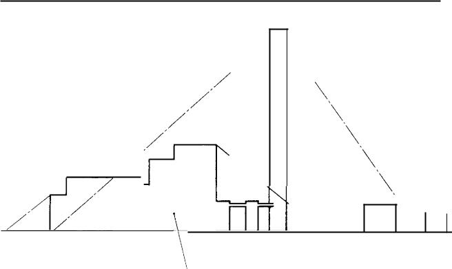
H t, 6.137 Collection area for a tall chimney
Hci. 6.138 Zone of protection for structures up to 20 m high
Jurged leader progresses, the electric field between
kiIi and earth intensifies until the field at the earth ‘uriace is sufficiently high for an upward streamer
'0 be launched to meet the downward leader, and so
Weighting factor A (use of structure)
|
Use to which structure is put |
|
Value of |
|
|
|
factor A |
||
|
|
|
||
|
|
|
|
|
|
Houses and other buildings of comparable ;ire. |
|
0.3 |
|
|
Houses and other buildings of comparable s i ze |
|
|
|
|
with outside aerial. |
|
0.7 |
|
|
Factories, workshops and laboratories. |
|
1.0 |
|
|
Office blocks, hotels, blocks of flats and other |
|
|
|
|
residential buildings other than those included |
|
|
|
|
below. |
|
1.2 |
|
|
Places of assembly, e.g., churches, halls, theatres, |
|
|
|
|
museums, exhibitions, department stores, post |
|
|
|
|
offices, stations, airports and stadium structures. |
|
|
|
|
Schools, hospitals, children's and other homes. |
|
1.7 |
|
|
|
|
|
|
|
TABLE 6.29 |
|
|
|
|
Type of structure weighting factor B |
|
|
|
|
|
|
|
|
|
Weighting factor B (type of structure) |
|
|
|
|
|
|
|
|
|
Type of construction |
|
Value of |
|
|
|
factor B |
||
|
|
|
|
|
|
|
|
|
|
|
Steel framed encased with any roof other than metal. * |
0.2 |
||
|
Reinforced concrete with any roof other than metal. |
0.4 |
||
|
Steel framed encased or reinforced concrete with |
|
|
|
|
metal roof. |
0.8 |
||
|
Brick, plain concrete or masonry with any roof other |
|
|
|
|
than metal or thatch. |
1.0 |
||
|
Timber framed or clad with any roof other than metal |
|
|
|
|
or thatch. |
1.4 |
||
|
Brick, plain concrete, masonry, timber framed but |
|
|
|
|
with metal roofing. |
1.7 |
||
|
Any building with a thatched roof. |
2.0 |
||
|
|
|
|
|
*A structure of exposed metal which is continuous down to ground level is excluded from the table as it requires no lightning protection beyond adequate earthing arrangements.
complete the path for the return stroke. Upward streamers are launched from the earth's surface at points of greatest electric field intensity, and they can travel in any direction towards the downward leader. Tall structures give a high degree of field enhancement and therefore upward streamers can start preferentially from these. This is particularly true for high current density flashes where higher charges are involved and hence longer upward streamers. However, downward leaders do not have to travel directly downwards, it is therefore possible for them to approach a tall structure in such a manner as to allow a strike part way down, as shown in Fig 6.139.
577

Cabling |
Chapter 6 |
|
|
|
|
TABLE 6.30
Contents or consequential effect weighting factor C
Weighting factor C (contents or consequential effects)
Contents or consequential effects |
Value of |
||
factor C |
|||
|
|
||
|
|
||
Ordinary domestic or office buildings, Factories and |
|
||
workshops ilot |
tainable or specially |
|
|
susceptible contents. |
|
0.3 |
|
Industrial and agricultural buildings with specially |
|
||
susceptible * contents. |
|
0.8 |
|
Power stations, gas installations, telephone exchanges, |
|
||
radio stations. |
|
L.0 |
|
Key industrial plants, ancient monuments and historic |
|
||
buildings, museums, art galleries or other buildings |
|
||
with specially valuable contents. |
1.3 |
||
Schools, hospitals, children's and other homes, places |
|
||
of assembly. |
|
/.7 |
|
|
|
|
|
This means specially valuable plant or materials vulnerable to fire or the results of fire.
TABLE 6.31
Degree of isolation weighting factor
Weighting factor D (degree of isolation)
|
Degree of isolation |
Value of |
|
factor D |
|
|
|
|
|
|
|
|
Structure located in a large area of structures or trees |
|
|
of the same or greater height, e.g., in a large town |
|
|
Or forest. |
0.4 |
|
Structure located in an area with few other structures |
|
|
or trees of similar height. |
1.0 |
|
Structure completely isolated or exceeding at least |
|
|
t wice the height of surrounding structures or trees. |
2.0 |
|
|
|
TABLE 6.32
Type of country weighting factor E
Weighting factor E (type of country)
Type of country |
Value of |
|
factor E |
|
|
|
|
|
|
|
|
Flat country at any level |
0.3 |
|
Hill country |
1.0 |
|
Mountain country between 300 m and 900 m |
1.3 |
|
Mountain country above 900 m |
1.7 |
|
|
|
|
However, such strikes are likely to be low current density since these have shorter upward streamers. The length of the last leader to complete the strike is called the striking distance. Since the last leader is not confined by direction, all points equidistant from the end
DOWNWARD LEAD E9
LENGTH OF LAST LEADER
STEP HIGH D,ARGE.
LENGTH OF LAST LEADER STEP 'LOW CHARGE,
ler
 \kr
\kr
FIG. 6.139 Lightning strikes on tall structures
of the leader prior to the last jump, can be considered equally likely to receive a lightning strike. Therefore the surface of a sphere having a radius equal to the striking distance can be used to define the zone of protection as shown in Fig 6.140. The practice of using an imaginary sphere in this manner to predict the zone of protection is known as the rolling sphere method, This name is derived from the need, with complex. shaped buildings, to roll the imaginary sphere around and over it to determine the zones of protection. As already stated, the radius of the sphere is equal to the striking distance which is related to the charge and hence current density of the strike. Since the current density varies from one strike to the next a statistical approach has to be used. BS6651; 1985 originally recommended a sphere radius of 20 metres but this is being amended to 60 metres for general use, as this is considered to be much more practical. For buildings with explosives or highly flammable contents, however, the 20 metre radius sphere is still recommended.
We must now consider how to apply the method of risk analysis to power station structures. Firstly we must establish an acceptable overall risk factor. As stated above, BS6651: 1985 recommends that for risks less than 10 -5 , lightning protection is not necessary while for risks greater than 10 - i, say 10 -4 , sound reasons would be required for not providing protection. Between these figures the need to fit protection is considered marginal, especially towards the lower figure, and other factors such as consequential effects and economics need to be taken into account. It will be demonstrated later in this section that the collec . tion area of power station main buildings is such that a lightning protection system will be required even If the lower risk value of 10 -5 is used. However, for other smaller structures this lower value of 10 considered to be financially unjustified for the nsk
578

■glIPP"'
Lightning protection
6C ,
SC,
25.
ZONE PROTEC 7.0'1 agov - cED BY L,C,,-17 ■4,;,3
PROTECMON SYSTEMS OF 9 -1.PLOqNG AND CHIMNEY
FIG. 6.140 Zone of protection defined by rolling sphere method
risiIv d, bearing in mind that any high density current ,!rikes are likely to be to the chimney or main buildings.
;1,:refore, for these smaller structures, the risk is as- cd a probability of 5 x I0 , this being :he mid-point between the values of 10 -5 and 10 -4 . As far as the weighting factors outlined in the preious Section 12.2 are concerned, a number of these can !, e treated as standard for all power station buildings. respect to weighting factor A for the use of the
,'ru.Jure for power station buildings, a value of 1.0 is
,n , idered appropriate. Weighting factor C for the
,::. uaure contents is set at 1.0 for power stations. The
.4 , 1 majority of power stations are sited in flat country therefore a value of 0.3 is selected for weighting or E. Weighting factors B and D, which relate to
.re of construction and degree of isolation respectivehave to be considered individually for each structure.
1fal,in2 defined zones of protection and the method ci risk analysis, we can now consider the requirements
.or individual structures, starting with the tallest. For
tthsil-fired power station the tallest structure will be ihe main chimney and, as already discussed, since this li kely to receive any high current density strikes it
• essential that it is fitted with an efficient protection ‘,.•tem. Gas turbine and auxiliary boiler house chimare, also of sufficient height that lightning protec-
•:ofl. s! sterns must be fitted.
Considering main buildings such as turbine halls or 1-0.11er houses, these are too large to be within the zone
or protection of the chimney as defined by the rolling 'P here method and therefore it is possible for them
to be struck by lightning. It is of course possible for
0
main buildings to be within the 45 cone volume of the chimney (as shown in Fig 6.141) and in this case it is possible to claim that the main buildings are less likely to be struck by lightning, particularly by high density strikes, than if the chimney were not there. This degree of protection can be taken into account by selecting a value of 0.4 for weighting factor D from Table 6.31. Main power station buildings are typically steel framed or reinforced concrete with a steel roof, for which a value of 0.8 is appropriate for weighting factor B. Therefore, for main buildings:
Overall weighting |
=AxBxCxDxE |
factor |
= 1 x 0.8 x 1 x 0.4 x 0.3 |
|
0.096 |
From Section 12.2: P = A, x Ng x 10 -6 |
|
and P 0 |
=PxAxBxCxDxE |
Po
A, —
0.096 x Ng x 10 -6
Taking a median value of Ng = 0.5 from Fig 6.135 and a value of 5 x 10 -5 for the maximum acceptable risk, the maximum allowable effective collection areas, as defined in Section 12.1, is:
A0 — |
5 x 10 —5 |
|
0.096 x 0.5 x 10 |
6 |
|
|
|
|
=. 1042 m 3 |
|
|
579
W."
Cabling |
Chapter 6 |
|
N.
ZONE - SOME PPOTECT!ON PROVDEG BY OTHER BUILDINGS OR STRUCTURES
WITHIN 45 3 CONE OR WEDGE VOLUME
Flo. 6.141 45 0 cone of protection from chimney
This equates to a building size of some 20 m square |
(b) Structures which are within the 45 ° cone or wedge |
||||||
by 10 m high which is considerably smaller than any |
volume of chimneys or main buildings, but not |
||||||
main buildings. Even if the risk is increased to 10 -4 |
covered by (a) need to be assessed with respect |
||||||
thus doubling the collection area, the allowable build- |
to their collection area. As before, constants A, C |
||||||
ing size still does not approach that of power station |
and E are fixed and, since in this case a consider. |
||||||
main buildings. Therefore it is required that all main |
able degree of protection will be given by the taller |
||||||
buildings such as turbine halls and boiler houses be |
structures, a value of 0.4 is chosen for weighting |
||||||
fitted with a lightning protection system. |
factor D. As previously discussed, the maximum |
||||||
Whilst dealing with main buildings it is useful to |
allowable overall risk factor P o is taken as 5 x |
||||||
consider nuclear power stations where there is ob- |
10 -5 . |
|
|
|
|
|
|
viously no main chimney. Such stations tend to be |
Now the overall risk = A x BxCxDxE |
||||||
isolated and are taller than the few buildings that may |
|||||||
be in the local area. For this degree of isolation, a |
factor |
= IxBx 1 x 0.4 x 0.3 |
|||||
value of 2 for weighting factor D is considered ap- |
|
||||||
|
= 0.12B |
||||||
propriate. This will have the effect of reducing the |
|
||||||
|
|
|
|
|
|
||
collection areas, given above for buildings within the |
Maximum allowable - |
5 x i0 |
|||||
cone of chimneys, by a factor of five. Therefore quite |
|||||||
|
|
||||||
Ng x 10 -6 X 0.12 x B |
|||||||
clearly because of their size, the reactor and other |
collection area A, |
|
|
||||
main buildings will need to have a lightning protection |
|
416 |
|
|
|||
system fitted. |
A, |
|
|
||||
|
|
|
|
|
|||
We now need to consider the remaining smaller struc- |
|
|
Ng x B |
||||
|
|
|
|||||
tures that will be present on a power station site. The |
|
|
|
|
|
|
|
requirement for lightning protection will be dependent |
For any particular power station, Ng is selected |
||||||
on the degree of protection afforded by taller structures |
according to its location from Fig 6.135. Weighting |
||||||
and it is convenient to use three classes according to |
factor B is selected according to type of structure |
||||||
location: |
from Table 6.29. |
|
|
|
|
|
|
(a) Structures that are within the zone of protection |
(c) Structures which are outside any zone of protection |
||||||
of chimneys or main buildings as defined by the |
are again assessed on their collection area. As be |
||||||
rolling sphere method are not required to be fitted |
fore, constants A, C and E are fixed. In this case |
||||||
with a lightning protection. system. |
a value of 1 for weighting factor D is considered |
||||||
580

|
|
|
|
|
|
|
|
Lightning protection |
|
|
|
|
|
|
|
|
|
||
|
appropriate since there will be a number of struc- |
additional connection is required. The continuity of |
|||||||
|
tures of similar height and taller in the area. |
this connection should however be checked and not |
|||||||
|
|
|
|
|
|
|
|
merely assumed. |
|
|
\ow the overall risk = AxBxCxDxE |
|
|||||||
|
factor |
= IxBx 1 x 1 x 0.3 |
12.4.1 Main and gas turbine chimneys |
||||||
|
|
|
= 0.3B |
It is now standard practice to construct single and |
|||||
|
|
|
|
|
|
|
|
||
|
|
|
|
|
|
|
|
multi-flue chimneys from reinforced concrete, there- |
|
|
\laximurn allowable |
|
|
|
|
|
fore the lightning protection system details herein are |
||
|
|
|
Ng x 10 - 6 x 0.3 x B |
||||||
|
|
|
appropriate to that type of construction. |
||||||
|
.:ollection area A, |
|
|
||||||
|
|
|
|
|
|
The air termination is formed using the metallic |
|||
|
|
|
|
166 |
|
|
|||
|
|
A c |
|
|
cappings (or metallic flues if provided), ensuring that |
||||
|
|
|
|
Ng x B |
capping segments are adequately bonded together to |
||||
|
|
|
|
|
be electrically continuous. Where metallic cappings |
||||
|
|
|
|
|
|
|
|
||
|
For any particular power station, Ng is selected |
are not provided, a metal strip coronal band must be |
|||||||
|
according to its location from Fig 6.135. Weighting |
fitted to each flue. The connection from the air ter- |
|||||||
|
factor B is selected according to type of structure |
mination on each flue is brought down to a test clamp |
|||||||
|
from Table 6.29. |
|
|
|
|
|
as shown in Fig 6.142. In addition, the concrete wind- |
||
|
|
|
|
|
|
shields of multi-flue chimneys are also provided with |
|||
|
|
|
|
|
|
|
|
||
In summary, lightning protection systems shall be fitted |
a strip coronal band which is bonded direct to the |
||||||||
windshield reinforcement. This windshield corona] band |
|||||||||
|
,tructures as follows: |
|
|
|
|
|
|||
|
|
|
|
|
|
can be omitted if handrails are fitted since these can |
|||
|
|
|
|
|
|
|
|
||
• |
\fain, gas turbine and auxiliary boiler chimneys. |
form the air termination, but in this case handrail |
|||||||
• |
\lain buildings including boiler, turbine and reactor |
sections must be bonded together and direct to the |
|||||||
windshield reinforcement rods. Finally an external bond |
|||||||||
|
buildings, irrespective of height. |
||||||||
|
should be provided between reinforcement of flue and |
||||||||
|
|
|
0 |
|
|||||
• |
Buildings or structures that are within the 45 cone |
windshield where reinforcement is not continuous, as |
|||||||
|
or wedge zone of chimneys or main buildings but |
shown in Fig 6.142. Coronal bands and all connections |
|||||||
outside the protection zone as defined by the rolling sphere method, that have a collection area in excess
of A, = 4I6/(Ng x B). |
CORONAL BAND BONDED |
|
TO DOWN CONDUCTOR |
•Buildings or structures which are outside the 45 ° cone or wedge zone of chimneys or main buildings
that have a collection area greater than A, = |
DOWN CONDUCTOR |
166/(Ng x B). |
|
• All structures containing explosive or flammable |
DOWN CONDUCTOR |
materials shall be protected in accordance with |
FIOLDFASTS |
|
|
BS6651: 1985. |
|
12.4 Protection system design
I flL section is intended to give the principles of system Ln and therefore constructional details of mdidual components are not included. Reference should 1 'e made to GDCD Standard 83 for constructional
of components.
li ghtning protection scheme has three essential :1;:ments which are the air termination, the downconJuctors and the earth termination. The power station
, tri mures are discussed in the following sections with 7t.Lsrteet to these elements.
As a general requirement, the combined resistance earth of each lightning protection system should UI e\ceed 10 ohms. In addition, each individual light-
rmg protection system must be connected to the main ‘:allort earth network to reduce the risk of dangerous N'cntials occurring between earth systems. In cases here a connection exists via structural steelwork no
REINFORC EM EN T
TEST CLAMP
HANDRAIL BONDED
TO REINFORCEMENT
D4TERNAL BOND BE TWEEN
REINFORCEMENT OF FltA
AND WINDSHIELD WHERE
REINFORCEMENT IS NOT
CONTINUOUS
Flo. 6.142 Typical arrangement of air terminations and down conductors for multi-flue chimneys
681

Cabling |
Chapter 6 |
|
within 12 m of the flue top are to be formed using copper strip which has been seamless lead covered to protect it from the flue gases.
The reinforcement of the windshield should be utilised as the clowneonductor subject to the following conditions:
•"Ole reinforcement should be secured by tie wires at all laps and intersections, the laps being bonded by at least two tie wires.
•External connections should only be made to reinforcement that is part of a continuous mesh.
All metalwork including aircraft warning light access doors and handrails shall be bonded to the reinforcement. Bonding of small isolated metalwork such as steeplejack access fittings is not necessary. At intervals of approximately 45 m throughout the height of the chimney, all continuous vertical runs of metal including stairways, lift structures, cable armouring and reinforcement of windshield and flues should be bonded together. It is normally convenient to carry out such bonding at the levels at which aircraft warning lights are fitted. The downconductor system shall be brought out near ground level to a total of four test clamps spaced equally around the perimeter of the chimney. To ensure adequate current carrying capability, each test clamp should be bonded directly to a minimum of four reinforcement rods. In addition, where flues extend to the chimney base, the windshield and flue reinforcement should be bonded through to the base reinforcement.
An earth termination formed from earth rods should be provided adjacent to each test clamp position. Copper strip is used to connect the earth termination to the test clamp.
12.4.2 Main buildings
Where roofs are constructed from metal decking, complying with the minimum thicknesses given in Table 6.33, the roofing may be regarded as the air termination and externally applied tapes are not considered necessary.
This applies even if the decking is covered in insulation, such as bitumen felt, since these materials offer negligible resistance to lightning. When metal decking
TABLE 6.33
Roof thickness
Material |
Minimum thickness, mm |
|
|
|
|
Gals anised ocel |
0.5 |
|
Stainless steel |
0.4 |
|
Copper |
0.3 |
|
Aluminium and zinc |
0.7 |
|
l ead |
2.0 |
|
|
|
|
is used as the air termination it is important to ensure that there is adequate electrical continuity betwee n sheets, and between sheets and the steel framework, Where roofing is formed from non-conducting ma - terials, e.g., in-situ or precast reinforced concrete, air terminations in the form of metal strip mu st be provided around the perimeter and over the roof to form a mesh not exceeding 10 m x 20 m. Any
dons above the general roof level, e.g., parapet wails, vent pipes, heating and ventilating exhausts, should be bonded to the roof steelwork or the air termination network. If such projections are non-conducting, th ey need to be provided with metal strip air termination s bonded to the roof termination.
Where possible, steel or reinforced concrete column s should be utilised as downconductors. Columns fo r use as downconductors need to be nominated early in the civil programme to enable provisions to be made for the connection of air and earth terminations. The nominated columns should be spaced at intervals not exceeding 10 m around the perimeter of the building. For steel columns a welded boss should be provided for bonding connections. With reinforced concrete columns for bonding connections, a tag should be provided which is welded or clamped to at least four reinforcement bars to allow adequate current distribution. Sufficient bonding connections should be provided between metal decking or air termination networks at each column nominated as a down conductor.
At each concrete column used as a downconductor, the reinforcement should be tied to the floor reinforce. ment to form an earth electrode. In addition, the tag connection to the reinforcement at the bottom of the column should be bonded to the station earth network. Where steel columns arc used as downconductors, a tag should be provided at the column base which is connected either to the supporting pile (if present) or to at least four reinforcement bars in the base concrete. This tag is to be bonded to the boss at the base of the steel column and to the station earth network.
12.4.3 Other buildings
All other buildings which are deemed to require lightning protection, when assessed in accordance with Section 12.3 of this chapter, should be protected in the following manner.
Air terminations should be formed using the same techniques as described for main buildings in the previous Section 12.4.2.
Again where possible, as with main buildings, structural steel or reinforced concrete columns should be utilised as downconductors. Facilities should be Pro - vided to allow a connection to be made from the base of the column to an external earth electrode. This can be achieved by providing a lug or boss on the outside of the column, if exposed, or by the provision ()fa duct from the column base to an external earth Pit.
582

Lightning protection
here it is not possible to utilise the fabric of the ‘1,- wnconductors, then separate metal strip
building as d o
onductors have to be provided down the outside of building. The spacing of downconductors around
[ h e building should not exceed 20 m for buildings up '0 m high. For buildings over 20 m high, down-
need to be provided at intervals not ex- ding 10 m around its perimeter.
An earth termination consisting of copper-clad steel with ESI Standard 43-94 should
io e provided at the base of each downconductor. The onnection to earth is completed using copper strip
ua a test link. These test links should be located in a po,ition with suitable access for testing.
12.4.4 Buildings requiring special considerations
\‘, ben designing a lightning protection system it must he recognised that lightning currents will seek out the l o‘k est im pedance and hence the most direct path to
earth. It should be the design intent to provide low [-npedance paths around the perimeter of buildings,
thus reducing the magnitude of currents flowing through the building which might result in interference or ,ideflashing. For simple rectangular buildings, such as [hat shown in Fig 6.143, this can be achieved by nominating columns around the perimeter of the building for special treatment as downconductors or by using separate external downconductors. Where there are annexes attached to the building these can be readily incorporated by running tapes over the roofs.
However, for complex buildings such as that shown in Fig 6.144, special provisions are necessary if it is required to prevent substantial currents flowing through the building where sensitive equipment may be housed. In Fig 6.144 the building length is such as to demand a number of downconductors along its length. In this case it is not considered permissible to run conductors
down from the highest roof, across the lowest roof an d back up to the other roof to connect to the down-
FIG. 6.144 Protection scheme for a complex building design
conductors along the perimeter of the building. If downconductors were installed in this manner the lightning current from a strike at location A (Fig 6.144) would be unlikely to follow such a tortuous route and would seek a more direct route through the building structure, by sideflashing where necessary. The solution to this type of problem is to provide catenaries across the void to interconnect the air terminations on the two roofs. This provides a low impedance path to the peripheral downconductors and achieves a higher degree of current sharing between them.
12.4.5 Fuel oil storage tanks
This section relates to heavy oil and gas turbine fuel oil tanks. In these cases the tank structure itself forms the air termination and the downconductors. To facilitate connection to the earth termination, bosses should be provided near the base of the tank at intervals not exceeding 35 m around the perimeter of each tank. An earth termination formed from earth rods complying with ESI Standard 43-94 is provided at each boss location. The earth termination is connected to the boss, via a test link, using copper strip.
FIG. 6.143 Protection system for a simple rectangular building
12.4.6 Flammable gas production and storage plant
Hydrogen generation plant
In order to provide adequate protection against lightning, the complete hydrogen plant and storage area should be covered by a suspended horizontal air termination network. This applies even when the plant is in the protective zone of the chimney or main buildings. The network shall enclose all the buildings and storage areas of the plant and should be con-
583

IP"
Cabling |
Chapt er 6 |
|
|
|
|
structed in accordance with the requirements of British Standard Code of Practice BS6651: 1985, Clause 21. The. number of horizontal conductors is determined from the plant layout using a protective angle of up to 45 ° between conductors and a maximum of 30 0 outside the outer conductors, as shown in Fig 6.145. The height of the horizontal conductors needs to be sufficient to avoid any risk of flashover to the protected structure and due account must be taken of items such as vents that may be higher than the main structures. The minimum clearance of these conductors and their supports from the structure should be 2 m.
An earth electrode should be provided at the base of each conductor support and these are interconnected by a ring conductor. This ring conductor should preferably be buried to a depth of 0.6 m, but may be run above ground where this is more convenient for bonding other objects or for testing. All major metal forming parts of the protected structure, including continuous metal reinforcement, should be bonded together and connected to the lightning protection system. To achieve this, at least two connections should be made to the ring conductor and, if possible, connections should be equally spaced around the perimeter of the structure at intervals not exceeding 10 m. In addition, the ring conductor should be connected to the station earth system.
The materials and bonding should be in accordanc e with BS 6651: 1985, Clause 21, and particular atten.. lion is drawn to clauses 21.2.6 and 21.2.7 which detail bonding of pipes, cables, etc., entering the area, I n_ sulated flange points of the type shown in Fig 6.146 are to be fitted to the delivery main immediately out s ide the compound fence.
Propane storage cylinders
The propane cylinder storage compound is to be treated in a similar manner to the hydrogen generation pla nt.
12.5 Assessment of risks of sideflashing and interference
When a lightning protection system is struck by lightning, large potential differences are produced across it. The overall potential produced has two components. The first is the product of the current and the resistance to earth; the second is the product of the rate of change of current and the inductance of the downconductor system. Whilst there will be a phase difference between these components the worst case, which is given by the simple addition of the two products, is normally used in any assessment.
To illustrate this point, consider a building 20 m high fitted with an air termination and a single downconductor.
In Section 12.2 of this chapter we defined the maximum design current as 200 kA and, in Section 12.4, we require a maximum earth termination resistance
GABLE EARTH
RING AT EASE
OF MASTS
S,SPE'40ED A1A TERMINATION
M 1 C SOLT AND NUT
5.15 VENDED AIR TERMINATION
To STATION
EARTH NETWORK
ZONES OF PROTECT ON
AT MAST
ZONES OF PROTECTION
AT MAximum SAG OF
SERIAL CONDUCTOR
INSULA TING SLEEVE |
OS WASHER |
MINIMUM INSULATION RESISTANCE 2M ci AT 500 JOLTS |
|
Flu. 6.145 Typical catenary air termination system for |
|
flammable gas production and storage plant |
FIG. 6.146 Insulated flange point for a gas pipeline |
584

|
|
|
|
|
|
|
Lightning protection |
||
|
|
|
|
|
|
|
|||
or IC) om . |
Therefore the potential difference across |
For strip conductors, effective radius has to be used |
|||||||
|
|
and this can be calculated using the formula: |
|||||||
the earth termination is: |
|
||||||||
|
|
W + t |
|
||||||
|
VR |
IR = 200 x 10 3 |
x 10 = 2 MV |
|
|
||||
|
|
|
|
|
3.5 |
|
|
|
|
lienee the base of the downconductor will be raised |
|
|
|
|
|
||||
where W = strip width, m |
|
|
|
|
|||||
/ \IV above remote earth, |
|
|
|
|
|
||||
|
co nsider the second component which is the |
t = strip thickness, m |
|
||||||
rotential difference across the clownconductor. A down- |
|
|
|
|
|
|
|||
onductor tape has a self-inductance of the order of |
Having calculated the transfer inductance NIT, the |
||||||||
|
|
and front Section 12.2 we take the maxi- |
inductive voltage VL generated in the loop shown in |
||||||
mum rate of change of current to be 200 kA/As (2 x |
Fig 6.147 is given by the equation: |
|
|||||||
lo m |
s ). Therefore the potential difference across |
di |
|
|
|
|
|||
the height of the building is: |
|
|
|
|
|
||||
|
|
|
|
V L = (— |
X |
|
(kV) |
||
|
|
di |
x f XL |
dt ) max |
|
|
|
|
|
|
|
|
|
|
|
|
|
||
|
|
VL = (— |
Where 1' = loop length, m |
|
|
|
|
||
|
|
dt ) max |
|
n = number of downconductors that simul- |
|||||
|
|
downconductor length, m |
|||||||
i% here |
e |
taneously share the lightning current |
|||||||
|
Ls = self-inductance |
|
Now taking the example shown in Fig 6.148, we have |
||||||
|
VL = 2 x 10 11 x 20 x 1.5 x 10 -6 |
||||||||
|
an earth cable bonding a cubicle down to the main |
||||||||
|
|
|
|
||||||
|
|
= 6 IVIV |
|
station earth network. The earth cable is run parallel |
|||||
|
|
|
|
with a downconductor at a distance of 4 m for a length |
|||||
Therefore, the total rise of potential of the air ter- |
of 20 m. For a 25 mm x 3 mm strip conductor: |
||||||||
mination above remote earth is: |
|
r e = (0.025 + 0.003)/3.5 = 0.008 |
|||||||
|
|
|
|
||||||
V = Viz VL = 2 + 6 = 8 MV
This simple example is pessimistic since the most onerous lightning parameters and earth electrode reistance have been used. Also, a single downconductor has been considered where in practice on a tall building :here would be many, which would reduce the induclance between the air and earth terminations considerably. Nevertheless it does demonstrate the order
of magnitude of potential gradients that can occur in sructures when subjected to a lightning strike. These %oltages do not constitute a danger to the structure
;! , elf, but they can have an effect on equipment such as pipes or cables in the vicinity of the downconductors.
From this point of view it is necessary to determine
.nductively-generated voltages to assess the risk of side- :lashes between equipment and downconductors.
For the calculation of voltages between a lightning
, onductor and other metalwork we cannot use selfdiductance as in the previous example. In this case
eneed to use the transfer inductance, which is the
,oupling generated by the self-inductance minus the mutual inductance to the metalwork. From BS6651:
19 8) the transfer inductance MT may be calculated Irorn the formula:
MI = 0.47 logio — ti1-1/m
distance between downconductor and other metalwork, m
r = radius of downconductor, m
Now MT --- 0.46 log 10 (4/0.0008) = L24 pi H/rri
For a design value of rate of change of current of 200 kA/its (2 x 10" A/s):
VL = 2 x 10 11 x 20 x 1.24 x 10 -6 = 5 x 10 6 V
DOWN coNouctoa
BOND |
METAL PIPE CONDUIT |
|
iRu , :xiNG OP 07.EP |
|
METALWORK |
FIG. 6.147 Transfer inductance of a simple loop
585

Cabling |
Chapt er 6 |
|
|
|
|
44,
EARTH
ZA.BLE
CONCLC TOR
VAT.CN
EARTH RING
Fic. 6.148 Inductive voltage generated in a toop
Taking the dielectric strength of air to be 500 kV/m it is clear that sideflashing could occur between the cubicle and the downconductor.
Now it is interesting to compare the difference when a reinforced column is used as the downconcluctor instead of metal strip. Consider a concrete column 1 m square with reinforcement to within 0.05 m of the surface, so that all reinforcement is contained in a square having 0.9 m sides. A reasonable approximation of the inductance for such a group of reinforcement may be obtained by treating it as a box-section of the same dimensions. To calculate the inductance it is first necessary to calculate the effective radius thus:
W + t |
0,9 + 0,9 |
IC — |
— 0.51 m |
3.5 |
3.5 |
Using the same physical arrangement and lightning parameters as in the previous example we have:
MT = 0.46 login (S/r)
=0.46 login (4/0.51)
=0.41 gli/m
di |
eMT |
And VL |
|
dt |
max |
= 200 x 10 11 x 20 x 0.41 x 10 -6
VL = 1.64 x 10 6 V
Again taking the dielectric strength of air as 500 kV/ rn, the flashover distance is:
|
1.64 x 10⁶ |
|
D — |
|
— 3.28 m |
|
500 x 10 3 |
|
The air space between the column and the panel is the spacing, less half the column width which is 3.5 m, therefore sideflashing should not occur. This demon. strates one of the many advantages in using the building structure as a downconductor since the larger size of the column has had the effect of reducing the inductively-generated voltage by a factor of 3 compared with that obtained using a metal strip down_ conductor.
Al! the examples so far have only considered a single downconductor, whereas in practice any large building will have a number of downconductors which will share the current to some degree. The formula for induced voltage (VT) has a factor n which represents the number of downconductors. The basic formula therefore assumes that the value of di/di is equally shared by the downconductors. However, BS6651: 1985 recognises that in rectangular or square buildings with more than four downconductors, the corner down. conductors take a disproportionately large share of the total current. It is therefore recommended that a factor of 30% be added to the inductive voltage generated by corner downconductors. Conversely, in the central area of structures having many downconductors, the value of di/dt is lower by approximately 30%.
As an example, consider a building which utilises twelve reinforced concrete columns (having the same dimensions as the previous example) as downconductors. Now for metalwork bonded at the bottom to the downconductor and run parallel for 20 m at a distance of 2 m:
2
MT = 0 . 46 log IP ( —) = 0.27 gH/m
|
0.51 |
|
and |
|
|
di |
em-r |
|
VL = (;)max |
71— |
|
|
|
|
= 2 x 10 11 |
x |
20 x 0.27 x 10 -6 |
|
||
|
12 |
|
VL = 90 kV
586