

reading / British practice / Vol D - 1990 (ocr) ELECTRICAL SYSTEM & EQUIPMENT
.pdf
|
|
|
|
|
|
Earthing systems |
|
|
|
|
|
||
|
|
The actuator cable armour is insu- |
• |
Bonding of cable supporting steelwork In locations |
||
|
|
lated from earth. The screen of the |
|
where cable support steelwork is directly connected |
||
|
|
flexible power and control cables is |
|
to the station structural steelwork no additional |
||
|
|
earthed at the actuator earth stud. |
|
bonding is required. Where, however, cable support |
||
Cnarmoured cable and cables requiring no connec- |
|
steelwork is insulated from the station steelwork |
||||
|
(e.g., concrete cable tunnels) the steelwork should |
|||||
• |
|
|
||||
|
|
be bonded direct to the main station earth network. |
||||
:i on to armour |
|
|
||||
0 |
Stuffing gland |
|
This connection is made onto every section of in- |
|||
|
sulated steelwork using any convenient station earth |
|||||
|
|
|
|
|||
|
Z |
No gland. |
|
network cable being carried on that section of steel- |
||
|
|
|
|
work. In cases where there is no earth cable on the |
||
f.ible 6.'6 shows |
gland bonding codes that may be |
|
section of steelwork, a separate earth cable of 35 |
|||
|
|
mm |
2 |
cross-section shall be used, this cable being |
||
with equipment. A block cable diagram |
|
|
||||
ated |
|
|
connected into the nearest adjacent section of earth |
|||
:hc „i ng a typical application of bonding codes for |
|
|||||
|
network. |
|||||
rol and instrumentation cabling is included as Fig |
|
|||||
6 1 , 8. A similar block cable diagram for power cabling |
• |
Bonding of station perimeter fences Perimeter fences |
||||
— hown in Fig 6.129. |
|
are connected to earth by means of separate earth |
||||
The sizes of cable gland bond connections should |
|
|
|
|
||
!-‘,: a , follows:
• Insulated cable glands for 11 kV cables Where re-
quired, the bond for an insulated cable gland should
consist of an aluminium bar arranged to provide the shorting strap across all glands of the circuit
and the connection to the switchgear earth bar. This aluminium bar should have a minimum cross-
ectional area of 300 mm 2 .
• Insulated cable glands for 3.3 kV and 415 cables
For single core cable circuits, when required, the bond should consist of aluminium bar arranged to provide a shorting strap across all glands of the circuit and also connect to the switchgear earth bar. this aluminium bar should have a minimum cross- , ectional area of 300 mm 2 .
For multicore cable circuits, where the cable armouring is utilised as the earth reiurn circuit for he plant, the earth bonds at both ends of the cable shall use an earth cable of cross-section not less :han half that of the power cable core, with a minimum cross-section of 4 mm 2 .
• rfmtrol and instrumentation insulated cableglands
\‘ here cable gland earth bonds are required they shall be 4 mm 2 stranded copper earth cables.
P'.int bonding arrangements for extraneous metalwork:
▪ Bonding of structural steelwork All major vertical
, teel columns of the structural steelwork shall be bonded together and to the main earth network
"oh a 300 mm 2 cable. The connection to each steel
Lolumn is made via a suitable connecting lug which hould be welded to the appropriate steel columns
under the main steelwork contract. The interconnections between columns is carried on the cladding support steelwork or other adjacent steelwork. Connections to the earth electrodes should be made
dr all locations where the steelwork bonds pass an earth electrode position.
Electrical plant compound fences shall be connected to earth as for station perimeter fences and, in addition, a separate connection shall be made from the fence to the main earth network associated with the plant in the compound. This connection shall be a 10 mm 2 earth cable.
11.6 Testing
11.6.1 Earth resistivity measurement
The method of soil resistivity measurement most commonly used is that derived by Dr. F. Wenner [301,
In practice the method uses four electrodes driven into the ground in a straight line with equidistant spacing 'a' as illustrated in Fig 6.130. To obtain accurate results it . is important that the electrode depth does not exceed one twentieth of the electrode spacing 'a'. The outer two electrodes are used to circulate current and the inner two measure the ground potential difference. This is carried out using an earth tester which has the appropriate four terminals for connection to the electrodes and gives a direct reading in ohms. Assuming the soil to he homogeneous the value of soil resistivity is given by:
Q = IiraR
where R is the resistance measured by the instrument
If the distance 'a' is increased, the current will penetrate deeper into the ground and the measured value of resistivity will be related to this greater depth. To access the resistivity at various depths, a series of measurements are taken with increased electrode spacings
567
Cabling |
|
|
|
|
Chapter 6 |
||
|
|
|
|
|
|
|
|
|
TABLE 6.26 |
|
|
|
|
|
|
|
Gland bonding codes relative to equipment |
|
|
|
|
|
|
|
|
|
|
|
|||
|
Equipment |
Cables |
Bonding code |
|
|
||
|
|
|
|
|
|
|
|
|
Switchgear |
11 |
kV |
Q |
|
|
|
|
|
33 |
kV |
t- |
|
|
|
|
|
|
|
|
|
||
|
|
415 V |
|
|
|
|
|
|
|
Multicore |
.- |
|
|
|
|
|
|
|
|
|
|
|
|
|
Interconnections between switchboards |
11 |
kV |
A at Unit |
1 |
|
|
|
|
B at Unit 2 |
|
|
|||
|
|
|
|
|
|||
|
|
|
|
|
|
||
|
|
3.3 |
kV |
A at Unit 1 |
|
|
|
|
|
B at Unit |
2 |
|
|
||
|
|
|
|
|
|
||
|
|
|
|
|
|
||
|
(e.g., Unit 1 and Unit 2) |
415 |
V |
A at Unit 1 |
|
|
|
|
|
B at Unit 2 |
|
|
|||
|
|
|
|
|
|||
|
|
|
|
|
|
||
|
|
Multicore |
A at Unit 1 |
|
|
||
|
|
B at Unit |
2 |
|
|
||
|
|
|
|
|
|
||
|
|
|
|
|
|
|
|
|
Motors |
II |
kV |
B |
|
|
|
|
|
3.3 |
kV |
A/B * |
|
|
|
|
|
415 |
V |
A/B 4. |
|
|
|
|
|
|
|
|
|
|
|
|
Transformers |
Ii |
kV |
B |
|
|
|
|
|
Multicore |
B |
|
|
|
|
|
|
3.3 |
kV |
A/B * |
|
|
|
|
|
415 |
V |
A/B * |
|
|
|
|
|
|
|
|
|
|
|
|
Distribution boards |
415 |
V |
A |
|
|
|
|
|
|
|
|
|
|
|
|
Equipment fed from distribution boards |
415 |
V |
A |
|
|
|
|
|
|
|
|
|
|
|
|
Plant-mounted transmitters |
Multipair |
B |
|
|
|
|
|
(pressure switches, limit switches, transducers, etc.) |
Multicore |
B |
|
|
|
|
|
|
|
|
|
|
|
|
|
Network marshalling boxes |
Multipair |
R, P or S |
|
|
|
|
|
|
|
|
|
|
|
|
|
Network marshalling cubicles, |
Multipair |
R, P or S |
|
|
|
|
|
(except control room unit and |
|
|
|
|||
|
Multicore |
B |
|
|
|
||
|
transmission marshalling cubicles) |
|
|
|
|||
|
|
|
|
|
|
|
|
|
|
|
|
|
|
|
|
|
Control room unit and transmission marshalling |
|
|
|
|
|
|
|
cubicles, (except transmission end of inter- |
Multipair |
H |
|
|
|
|
|
connections between them) |
|
|
|
|
|
|
|
|
|
|
|
|
|
|
|
Transmission marshalling cubicle ends of inter- |
|
|
|
|
|
|
|
connections to control room unit marshalling |
Multipair |
B |
|
|
|
|
|
cubicles |
|
|
|
|
|
|
|
|
|
|
|
|
|
|
|
Control room panels and desks |
Multipair |
B |
|
|
|
|
|
|
|
|
|
|
|
|
|
Interlock cubicles |
Multicore |
A |
|
|
|
|
|
|
|
|
|
|
|
|
|
* See Fig 6.129 |
|
|
|
|
|
|
568

•■ |
r |
|
L |
c; |
|
|
|
-14
|
|
|
|
|
|
|
|
|
|
|
|
ANBL |
|
|
|
|
|
|
|
|
|
|
|
|
|
|
|
|
|
|
|
|||
|
LIOlik. AN. XI |
|
|
|
|
|
|
|
|
|
|
|
|
|
|
|
|
|
|
|
|
|
|
|||||||||||
|
MAHSMAtLfr C WC, |
|
|
|
|
|
|
|
|
|
|
OUBALLE ct |
. |
|
|
|
|
|
|
|
|
|
|
|
|
|
|
|
|
|
|
|||
|
|
|
|
|
|
|
|
|
|
|
|
|
|
|
|
|
|
|
|
|
|
|
|
|
|
|
|
|||||||
|
|
|
|
|
|
|
|
|
|
|
|
|
|
|
|
|
|
|
|
|
|
|
|
|
|
|
|
|
|
|
|
|
|
|
|
|
|
|
|
|
|
|
|
|
|
|
|
|
|
|
|
|
|
|
|
|
|
|
|
|
|
L. AHEM |
|
|
|
||||
|
|
|
|
|
|
|
|
|
|
|
|
|
|
|
|
|
|
|
|
|
|
|
|
|
|
|
BC. .0 OW BYLLar, |
|
|
|
|
|
|
|
|
|
|
|
|
|
|
|
|
|
|
|
|
|
|
|
|
|
|
|
|
|
|
|
|
|
|
|
|
|
|
|
|
|
|
|
|
|
|
|
|
|
|
|
|
|
|
|
|
|
|
|
|
|
|
|
7 |
|
|
|
||||||||||
|
|
|
|
|
|
|
|
|
|
|
|
|
|
|
|
|
|
|
|
|
|
|
|
|
|
|
|
|
|
|
|
IV., I no, |
inv.vy.r..1 |
|
|
|
|
|
|
|
|
|
|
|
|
|
|
|
|
|
|
|
|
|
|
|
|
|
|
|
|
....LIAO. BOX |
|||||||
|
|
|
|
|
|
|
|
|
|
|
|
|
|
|
|
|
|
|
|
|
|
|
|
|
|
|
|
|
|
|||||
|
|
|
|
|
|
|
|
|
|
|
|
|
|
|
|
|
|
|
|
|
|
|
|
.4.14,.../.0.G Eli N |
|
|
|
|||||||
|
|
|
|
|
|
|
|
|
|
|
|
|
|
|
|
|
|
|
|
|
|
|
|
|
|
|
|
|
|
|
|
|
|
|
|
|
|
|
|
|
CLsSJcLe |
|
|
|
|
|
|
|
|
|
|
|
|
|
|
|
|
|
|
|
|
|
|
|
|
|
|
|
|
|
|
|
|
|
|
|
|
|
|
|
|
|
|
|
|
|
|
|
|
|
|
|
|
|
|
|
|
|
|
|
|
|||
|
|
|
|
|
|
s rd. 1 up |
|
|
110k |
|
|
|
|
|
|
|
|
|
|
|
|
|
|
|
|
|
|
|
|
|
||||
|
|
|
|
|
|
|
|
|
|
|
|
|
|
|
|
|
|
|
|
|
|
|
|
|
|
|
|
|
|
|
|
|
||
|
|
|
|
|
|
|
|
|
|
|
|
|
|
|
|
|
|
|
|
|
|
|
|
|
|
|
|
|
|
|
|
|
|
|
|
|
|
|
|
|
|
|
|
|
|
|
|
|
|
|
|
|
|
|
|
|
|
|
|
|
|
|
|
|
|
|
|
|
|
|
|
|
|
Sr. |
|
|
1=40 |
|
|
|
|
|
|
|
|
|
|
|
|
|
|
|
|
|
|
|
|
|
|
|
|
|
||
|
|
|
|
|
|
|
|
|
|
|
|
|
|
|
|
|
|
|
|
|
|
|
|
|
|
|
|
|
|
|
|
|||
|
|
|
|
|
|
|
|
|
|
|
|
|
|
|
|
|
|
|
|
|
|
|
|
|
||||||||||
|
|
|
|
|
|
|
|
|
. 4 |
|
• 4111.1 |
|
|
|
|
|
|
|
|
|
|
|
|
|
|
|
||||||||
|
|
|
|
|
|
|
|
|
|
|
|
|
|
* SWUM * |
|
|
|
|
|
|
|
|
|
|
|
|
|
|
|
|||||
|
|
|
|
|
|
|
|
|
|
|
|
|
|
|
|
|
|
|
|
|
|
|
|
|
|
|
|
|
|
|
|
|
|
|
|
|
|
|
|
|
|
|
|
|
|
|
|
|
|
|
|
|
|
|
|
|
|
|
|
|
|
|
|
|
|
• |
NI I |
|
|
|
|
|
|
|
|
|
|
|
|
|
|
|
|
|
|
|
|
|
|
|
|
|
|
|
|
|
|
|
|
|
|
|||
|
41.41,151140.14.1, BO |
|
|
|
|
|
|
|
|
|
|
|
|
|
|
|
|
|
|
|
|
|
|
|
|
|
▪ |
5101001,0l.. |
|
|
||||
r |
|
|
|
|
|
|
|
|
|
|
|
|
|
|
|
|
|
|
|
|
|
|
|
|
|
|
|
|
|
|
||||
|
|
|
|
|
|
|
|
|
.015.41.1.114O |
|
|
|
|
|
|
|
|
|
|
|
|
|
|
|
|
|
|
|
|
|
||||
|
|
|
|
|
|
|
|
|
004 |
|
|
|
|
|
|
|
|
|
|
|
|
|
|
|
|
|
|
|
|
|
|
|
|
|
|
|
|
|
|
|
|
|
|
|
|
|
|
|
|
|
|
|
|
|
|
|
|
|
|
|
|
|
|
|
|
|
|
|
|
|
|
|
|
|
|
|
|
|
|
|
|
|
|
|
|
|
|
|
|
|
|
|
|
|
|
|
|
|
|
|
|
|
|
|
|
|
|
|
|
|
|
|
|
|
|
|
|
|
|
|
|
|
|
|
|
|
|
|
|
|
|
|
|
|
|
|
|
||
|
|
|
|
|
|
|
|
|
|
|
|
|
|
|
|
|
|
|
|
|
|
|
|
|
BOBLB' |
|
|
|
||||||
|
|
|
|
|
|
|
|
|
|
|
|
|
onTUOTOIN LOGO CENINt: |
|
|
|
|
|
|
|
|
|
|
|
|
|
|
|||||||
|
|
|
|
|
|
|
|
|
|
|
|
|
|
|
|
|
|
|
|
|
|
|
|
|
|
|
|
|
|
|
|
|
|
|
|
|
|
|
|
|
|
|
|
|
|
|
|
|
|
|
|
|
|
|
|
|
: voScuo■ ItU |
|
|
|
|||||||||
|
|
|
|
|
|
|
|
0,11019 |
|
|
|
|
|
|
|
|
||||||||||||||||||
|
|
|
|
|
|
|
|
|
|
|
|
|
|
|
kAJ.In 6^11 |
: |
|
|
|
|
SCONE TI 0001 |
|
|
|
|
|
|
|
|
|
|
|
||
|
OVINCLf L0411 |
|
|
|
|
|
|
|
|
|
|
|
|
|
|
|
|
CE.B-111=1 |
|
|
|
|
|
|
|
|
|
|
|
|||||
|
|
|
|
|
|
|
|
|
|
|
|
|
|
|
|
|
|
|
||||||||||||||||
|
|
|
|
|
|
|
|
|
|
|
|
|
|
|
|
|
|
|
|
|
|
|
|
|
|
|
|
|
|
|||||
|
|
|
|
|
|
|
|
|
|
|
|
|
|
|
|
|
|
|
|
|
|
|
|
|
|
|
|
|
|
|||||
|
|
|
|
|
|
|
|
|
|
|
|
|
|
|
|
|
|
|
|
|
|
|
|
|
|
|
|
|
|
|
|
|
|
|
|
|
|
|
|
|
|
|
|
|
|
|
|
|
|
|
|
|
|
|
|
|
|
|
|
|
|
|
|
Oh I ALA |
|
|
|
||
|
|
|
|
|
|
|
|
|
|
|
|
|
|
|
|
|
|
|
|
|
|
|
.1 |
|
|
|
|
|
||||||
|
|
|
|
|
|
|
|
|
S....CIK.e |
|
|
|
|
|
|
|
|
|
|
|
|
|
|
|
|
|
|
|
||||||
|
|
|
|
|
|
|
|
|
|
|
|
|
|
|
|
|
|
|
|
|
|
|
|
|
|
|
||||||||
|
|
|
|
|
|
|
|
|
|
|
|
|
|
|
|
|
|
|
|
|
MOM, |
|
Cur I vok |
Sm_nnew |
||||||||||
|
|
|
|
|
|
|
|
|
|
|
|
|
|
|
|
|
|
|
|
|
|
|
|
|
|
|
|
|
|
|
|
|
||
, cLAIBLL POMO.
MOP CON Ifich O.L.LX.BLC.. — T O on100004 N.NIlTn B..0
ER', 6.128 Gland bonding and earthing for control and insiroincitiation cabling
sweisAs butinJeD

likV SWIICHGEAN |
... , EAR tH BAH |
|
|
|
|
A
|
|
|
|
|
|
|
|
|
|
|
|
|
|
|
|
|
|
|
|
SjJ |
||||
|
|
|
|
|
|
|
EARTH CABLE FROM TANK |
|
|
|
|
|
|
|
|
|
|
|
|
|
|
|
||
|
|
|
|
|
|
|
TO SFA FON LARTH |
|
|
|
|
|
|
|
|
|
|
|
I HANSI- OMMER |
|||||
, |
|
|
|
|
|
|
|
|
|
|
|
|
|
|
|
|
||||||||
TRANS' |
|
|
|
|
|
|
|
|
|
|
|
|
|
|
|
|
|
I AMVA AND |
||||||
|
MVA |
|
|
|
|
|
|
|
|
|
|
|
|
|
|
|
|
|
||||||
|
|
|
|
|
|
|
EARTH CABLE FROM TANK |
|
|
SMALLER |
||||||||||||||
AND |
|
|
|
|
|
|
|
|
||||||||||||||||
|
|
|
|
|
|
1 |
0 STATION EARTH |
|
|
|
|
|
|
|||||||||||
LARGER |
|
|
|
|
|
|
|
|
|
|
|
|
||||||||||||
|
|
|
|
|
|
|
|
|
|
|
|
|
|
|
|
|
|
|
|
|
||||
|
|
|
|
|
|
|
|
|
|
|
|
|
|
|
|
|
|
|
|
|
|
|
|
|
|
|
|
|
|
|
|
|
|
|
|
|
|
|
|
|
|
|
|
|
|
|
|
|
|
|
|
|
A |
|
|
|
|
|
|
|
|
|
|
|
|
|
|
|
|
|
|
|||
|
|
|
|
|
|
|
|
|
|
|
|
|
|
|
|
|
|
|
|
|
|
|
||
|
|
TA |
|
3 Ay SWITCHGEAR |
EARTH BAR |
|
|
|
|
|
||||||||||||||
|
|
|
|
A IdA; |
|
|
|
|
|
|
|
|
|
|
|
|
|
|||||||
|
|
|
|
|
|
|
|
|
|
|
|
|
|
|
|
|
|
|
|
|
|
|||
|
|
|
|
|
|
|
|
|
|
|
|
|
|
|
|
|
|
|
|
|
|
|
||
|
|
|
|
|
|
|
|
|
|
|
|
|
|
|
|
|
|
|
|
|
|
|
|
|
|
|
|
|
|
|
|
|
|
|
|
|
|
TRANSFORMER |
|
|
|
|
|
||||||
|
|
|
|
|
|
|
|
|
|
|
|
|
|
|
|
KIVA |
|
|
|
|
|
|||
|
|
|
|
|
|
|
|
|
|
|
|
|
AND SMALLER |
|
|
|
|
|
||||||
|
TRANS F' |
|
|
|
|
|
|
|
|
|
|
|
|
|
|
|
|
|
|
|
||||
|
|
|
|
|
|
|
|
|
|
|
|
|
|
|
|
|
|
|||||||
|
2 MVA |
|
|
|
|
|
|
|
|
|
|
|
|
|
|
|||||||||
|
|
MOTOR |
S1-I LVRLY |
|
|
|
|
|
|
|
|
|
||||||||||||
|
|
|
|
|
|
|
|
|
|
|
|
|
|
|
||||||||||
|
|
|
|
|
|
|
|
|
LESS |
|
|
|
|
|
|
|
|
|
|
|
|
|
||
|
|
|
|
|
|
|
|
|
|
|
|
|
|
|
|
|
|
|
|
|
|
|
|
|
|
|
|
|
|
|
|
|
|
THAN |
|
|
|
|
|
|
|
|
|
|
|
|
|
||
|
|
|
|
|
|
|
|
|
16006W |
|
|
|
|
|
|
|
|
|
|
|
|
|
|
|
|
|
|
|
|
|
|
|
415v SWITCHGEAR EARTH BAR |
|
|
|
|
|
|||||||||||
|
|
|
|
|
|
|
|
|
|
|
|
|
|
|
|
|
|
|
|
|
|
|
||
|
|
|
A |
|
|
|
|
|
|
|
|
|
|
|
|
|
|
|
|
|
|
|||
|
|
|
|
|
|
|
|
|
|
|
|
|
|
|
|
|
|
|
|
|
|
|
|
|
|
|
|
|
|
|
|
|
|
|
|
|
|
|
|
|
|
A pri |
|
|
|
|
|
|
|
|
|
|
|
|
|
|
|
|
|
|
|
|
|
|
|
|
|
1 |
|
|||||
|
|
|
|
|
|
|
|
|
|
|
|
|
|
|
|
|
|
|
|
|
|
|
||
|
|
|
|
|
|
|
|
|
|
|
|
|
|
|
|
|
DISTRIBUTION BOARD |
|||||||
|
|
|
|
|
|
|
|
|
|
|
|
|
|
|
|
|
|
|
|
|||||
|
|
|
MOTOR |
|
|
MON311 |
|
|
|
|
|
|
|
|
|
|
|
|
|
|
||||
|
|
|
OVER |
|
|
UNDER |
|
|
|
|
|
AO. A |
Allt1 |
|
||||||||||
|
|
|
|
I RK LW |
|
|
|
|
|
|
|
|
|
|
|
|
|
|
|
|
|
|
||
A
3 3 KV SW/TCHGEAR EARTH OAR
|
|
|
|
|
|
|
|
A 611109,14 |
|
|
|
|
|
|
|
|
: |
|
|
|
|
|
|
) |
|
|
|
|
|
|
|
||||||||
|
|
|
|
|
|
|
|
|
|
|
|
|
|
|
|
|
|
||
|
MOTOR |
|
|
||||||
|
OVER |
|
|
|
|||||
|
1600MY |
|
|
|
|||||
4101/ SWITCHGEAR |
EARTH BAR |
||||||||
|
|
|
|
|
|
||||
|
|
A61•I' |
|
|
|
||||
|
|
|
|
|
|||||
|
A |
|
|
||||||
|
|
|
|
|
|
|
41 TV SWITCHGEAR |
EARTH BAR |
|
ISURRLIED VIA FUSES)
A
|
|
|
|
|
A4 |
A |
|
|
||||
|
|
|
|
|
|
|
|
|
|
|||
|
|
|
|
|
|
PANEL |
|
|
||||
|
|
|
|
|
|
|
|
|
|
|
|
|
|
|
|
|
|
|
|
|
|
|
DISTRIBUTION |
||
|
|
|
|
|
|
|
|
|
|
BOARD |
415V |
|
|
|
|
|
|
|
|
|
|
|
|
||
|
|
|
|
|
|
|
|
|
|
A id' - - - - - - - - |
||
|
|
|
|
|
|
|
|
|
|
|
|
|
|
A FIT - - - - - - - - - |
|
|
|
|
|
|
|
|
|||
|
|
|
|
|
|
|
|
|
|
|
|
|
Su13-DISTRIBUTION |
|
|
|
|
|
SUB-DrS1R/BUIION |
||||||
|
BORRD |
|
|
|
|
|
|
|
BOARD |
4150 |
|
|
|
|
|
iSV |
|
|
|
|
|
|
|
||
|
|
|
|
|
|
|
|
|
|
|
||
|
|
|
|
|
|
|
|
|||||
|
|
|
|
|
|
|
|
|
|
|
|
|
- -
TATTER?
(0 , 4r, L.1
[ 11AI FiY
I USE ROA
ti
5360 SWITCHGEAR |
EAR THRAII |
DC SWII rII.L Ali |
EARTH BAR |
|
|
|
|
|
|
|
|
|
|
|
|
|
|
|
|
|
|
A |
|
|
|
|
|
|
|
|
|
|
|
I N1ERCONNECTOR |
|
|
i / EARTH BAR |
|
|
|
|
||
|
|
|
DC DisiFtibu it/N |
||||||
|
|
3 AV SW ITCHGE AR |
|
||||||
|
|
|
BOAR() |
||||||
|
4SUPPLIED VIA FUSES) |
|
|
|
|
||||
|
|
|
|
|
|
|
|
|
|
|
|
|
A |
|
|
|
|
||
415v Swi I CHGEAR |
|
EARTH BAR |
|
|
|
|
|||
|
|
|
|
|
|
|
|
||
|
|
|
A 11.' |
|
|
|
|
|
|
9\— INTERCONNEC TOR
KEY
I NSutAl ED GLAND WITH INTEGRAL BONDING CONNEC TOR AND SCALE N E |
11,711 |
;INSULATED GLAND WITHOUT INTEGRAL BCNUNG CONNECTOR ULR WI I H ACHE TN IL limiNA FOR INSULATED GLAND WITH INTEGRAL BONDING CONNECTOR
I NSULATED III AND WITHOUT INTEGRAL BONDING CONNECTOR S tAtION EAR HI
GLAND BONDINL, CODE S
A ARMOUR GUNNEL:7'EO i0 STA] ION EAR fH
- ARMOUR rn4SuLA rELI MOM k All III AND SHROUD FIT TED OvLii GlAND ODDY
6.129 Gland bonding and earthing, for power cabling

|
Earthing systems |
|
|
|
TABLE 6.27 |
CURRENT |
Soil resistivity measurements |
SOURCE |
|
FIG. 6.130 Measurement of earth resistivity
lbout the central point. A typical set of measurements o Jk en in Table 6.27 and these are shown graphically
Fig 6.131.
The next step is to decide the best way to apply these roults. The first step must be to relate the electrode pacing to the effective depth to which the resistivity
k measured. CPI013 states that the average resistivity measured is for a depth equal to the electrode spacing.
':ome references will be found quoting the effective J,:nth to be in the range 0.6 to 0.75 times the electrode Spaing. If the soil is reasonably homogeneous, it will he found that the resistivity becomes substantially xnstant with depth as shown in Fig 6.131. The interpretation of effective depth is not critical under these
..onditions and to assume the effective depth is equal to electrode spacing should give acceptable results in practice. The formula used is derived on the assumption that the soil through which the current circulates is homogeneous, and this would be borne out if the soil- :-c.istivity remained constant as the electrode spacing
Electrode |
|
Test Point 'X' |
|
separation (a) |
|
|
|
|
R |
aR |
Apparent |
metres |
Si |
resistivity, |
|
|
ft m |
||
|
|
|
|
1 |
5.8 |
5.8 |
36.4 |
2 |
1.58 |
3.l6 |
20.0 |
3 |
0.92 |
2.76 |
17.3 |
4 |
0.68 |
2.72 |
17.1 |
5 |
0.49 |
2.45 |
15.4 |
6 |
0.46 |
2,76 |
17.3 |
7 |
0.43 |
3.01 |
18.9 |
8 |
0.36 |
2.88 |
18.1 |
9 |
0.36 |
3.24 |
20.4 |
10 |
0.29 |
2.9 |
18.2 |
12.5 |
0.26 |
3.25 |
20.4 |
15 |
0.19 |
2.85 |
17.9 |
17.5 |
0.17 |
2.98 |
18.7 |
20 |
0.19 |
3.80 |
23.9 |
|
|
|
|
was varied. In practice it will be found that the soil is non-homogeneous. To consider this in a simplified way, the value of resistivity for small values of electrode spacing can be said to represent the soil resistivity near the surface. Also, where the soil resistivity becomes sensibly constant with electrode spacing, this can be said to represent the underlying strata. The formulae
38
36
24
12
, 30
5
28
'6
2., 24
22
20
'8
16
' 4 0
|
4 |
|
|
|
4 |
18 |
1 8 |
20 |
|
|
FIG. 6.131 Graph of soil resistivity measurements as a function of electrode spacing
571

Cabling |
Chapt er 6 |
used in Section 11.4 of this chapter assume homogeneous soil conditions and therefore, where they are applied to non-homogeneous soil conditions, it is the 'effective' value of soil resistivity that should be used. The deduction of this effective value is complex, but it must lie between the values deduced for the surface and underlying strata soils. As a practical way of dealing with these difficulties, it is suggested that acceptable results will be obtained by taking the mean value of the measured values down to the maximum depth the proposed electrode will be driven.
For example, if it is required to drive an electrode to a depth of 10 metres, using the results given in Table 6.27 the effective resistivity is taken as:
e |
36.4 + 20.0 + 17.3 + 17.1 |
+ |
1 0 |
+ 18.2 |
|
|
15.4 + 17.3 + 18.9 + 18.1 + 20.4 |
|
Q = |
19.9 Qm |
|
Where the apparent resistivity starts increasing as the electrode spacing 'a' is increased, the underlying soil strata will be of higher resistivity and there will be less benefit in driving an electrode to this depth.
Soil resistivities will vary over a site and it is important to make measurements at each proposed electrode position. Where possible, these measurements should be made before site work commences since any buried earth conductors, cables or pipes can change the pattern of current flowing between the test electrodes, thus reducing the accuracy of the measurements.
11.6.2 Earth electrode resistance measurement
The resistance to earth of an electrode is measured using the same principle as for earth resistivity measurements, i.e., by passing current through the ground and measuring the potential difference across it. In this case the current is made to flow between the electrode under test and an auxiliary earth electrode driven into the ground. This auxiliary electrode may be specially driven for the test or could be any conveniently placed existing electrode. This auxiliary electrode should be placed at a sufficient distance away, such that it does not interfere with the natural distribution of current from the electrode under test. This distance will depend on the size and efficiency of the electrode under test and this will also affect the test method selected. For relatively small electrodes, such as individual pile electrodes recommended for power stations, a proprietary earth resistance measurement instrument can be used as described in (a) below. However, for large low-resistance electrodes such as the combined system on a power station or EHV system, the required distance is so large that a power frequency current injection system as outlined in (b) is necessary:
(a)Measurement of resistance by composite instrument
Measurements are made using the same instrumen t as that discussed in the previous Section 11.6.1 which is fitted with terminals for current injection and potential measurements, and provides a direct reading of resistance in ohms. A diagram_ matic arrangement of the test is shown in Fig 6.132 where X is the electrode under test, Y is the current electrode and Z the potential probe. To use the instrument in this mode, one of the potential terminals is connected to a current terminal and the electrode under test, the remaining terminals being connected to the potential and auxiliary current electrodes as appropriate.
The electrodes themselves are driven in a straight line. With the current electrode Y fixed, resistance measurements should be taken with the potential electrode Z at various distances from X. These measurements should be most frequent at the location where XZ = 0.6 XY since this is where the neutral zone or true resistance should be found. The results should be plotted as shown in Fig 6.133 and the flat portion which forms the neutral zone gives the resistance of the electrode under test. If a neutral zone is not found, the auxiliary electrode should be moved further away at, say, twice the previous distance from the electrode under test, and the test procedure repeated. If the neutral zone cannot be found with a practical distance between the electrode under test and the auxiliary current electrode, then the 61.8% distance rule as described by Tagg [29] should be invoked. This work by Tagg indicates that the true resistance should be indicated at a potential electrode position of 61.8% from the electrode under test to the auxiliary electrode position. Under these circumstances, it is suggested that a family of four graphs is constructed for various current electrode positions and the electrode resistance taken as the mean of the four resistance measurements at the 61.8wo potential electrode distance position. A typical set of results is shown in Fig 6.134.
(b)Measurement of impedance by power frequency current injection
For a large earth system it may be difficult to estimate its centre to apply the 61.8% rule dis-
CURRENT
SOURCE N..,
777A7 |
I |
|
Iz |
|
|
|
|
|
|
|
|
||||
|
|
|
|
||||
|
|
|
|
|
|
||
|
/7A\ <<\\///h ///, |
|
|
|
|||
|
|
|
|
||||
|
|
|
|
||||
FIG. 6.132 Measurement of earth electrode resistance
572

Earthing systems
|
E-E.7TPC,DE |
|
POTENT AL |
|
CURRENT |
. |
|
|
||
|
I.NCR "EST |
|
PROBE |
|
ELEC T RODE |
|
|
|
||
|
|
|
|
|
Z' |
|
'1, |
|
|
|
|
|
|
|
|
'CC. |
|
|
|
|
|
|
|
|
|
AZ |
1 |
|
|
|
||
|
|
|
|
|
'• |
|
I |
|
|
|
|
|
|
|
|
|
|
|
|
|
|
|
|
|
|
|
|
|
|
|
|
|
|
|
|
|
|
|
|
|
|
|
|
.T.E
NEUTRAL ZONE
|
|
|
|
|
|
|
|
|
|
|
|
|
|
|
|
|
|
|
|
|
|
|
|
|
|
|
|
|
|
|
|
|
|
|
|
|
|
|
|
|
|
|
|
|
|
|
|
|
|
|
|
|
|
|
|
|
|
|
|
|
|
|
|
|
|
|
|
|
|
|
|
|
|
|
26 |
30 |
40 |
30 |
60 |
70 |
30 |
30 |
|||||||
|
|
|
|
DISTANCE FROM ELECTRODE 3NDER TEST AZ |
|
|
|
|
|
|
||||
FIG. 6.133 Graph of electrode earth resistance showing neutral zone
cussed in (a) and to compensate for this the distance to the auxiliary current electrode may become prohibitively long. Furthermore, since the current injection and potential measurement leads are run in parallel (because the electrodes are in a straight li ne), an appreciable error can be produced due to the induction introduced into long measuring leads.
Under these circumstances, to improve accuracy,
it is preferable to increase the current circulating hrotivil the ground. To provide a sufficient current requires the use of a fairly substantial source,
, uch as a substation auxiliary supply or a diesel generator set. Where a diesel generator set is used,
ilie frequency should be set at say 60 Hz to allow
normal frequency (50 Hz) stray currents to be identified, When conducting such tests, the po-
tential measurement leads should be laid at 90 ° to the current injection leads to avoid induction. Further information on current injection tech-
niques is given in Engineering Recommendation
S34 [31] .
11.6,3 Commissioning tests
fl ,
if :ornpletion of the installation of the earthing system , aLter any major modifications, the following tests
.) oulci be carried out:
•Each individual electrode should have its resistance to earth measured using a composite instrument in the manner described in the previous Section 11.6.2. It is important that the test links are disconnected to ensure that only the electrode being considered is tested.
•Where individual electrode measurements are found to be higher than calculated, or where the calculated rise of earth potential is near the accepted limits, a current injection test should be carried out in the manner described in Section 11.6.2.
•Earth cable continuity tests should be completed as detailed in CP1013.
11.6.4 Routine tests
Routine testing consists of the following tests and timescales:
•Visual inspections of the station earth network system including earth electrode connections should be carried out at three-yearly intervals.
•The earth resistance of individual earth electrodes should be checked using the test methods detailed in Section 11.6.2 of this chapter at six-yearly intervals.
573
Cabling |
Chapt er 6 |
XY - 116- |
ELEcTaocE
RESISTANCE u
- - - - - - - -
Fir
0 3
/
02
DISTANCE SYNDICATED
 EACH CURVE

SEPARATION BETWEEN
ELECTRODE
 THE CURRENT ELECTRODE
|
|
|
|
|
|
|
|
|
|
|
|
|
|
|
20 |
30 |
40 |
50 |
60 |
S |
50 |
90 |
I N |
Ito |
120 |
130 |
'SO |
100 METRES |
|
DISTANCE OF ROYENTrAL ELECTRODE FROM ELECTRODE UNDER TEST
FIG. 6.134 Graph of electrode earth resistance where the neutral zone is not apparent
12 Lightning protection
12.1 General requirements
The function of a lightning protection system is to divert to itself a lightning discharge that might otherwise strike a vulnerable part of the protected structure, and to carry the current safely to earth. The requirements for the protection of structures against lightning are given in British Standard Code of Practice BS6651: 1985. It is necessary to interpret these requirements
for power station applications and this is carried out
within GDCD Standard 83. |
of |
It should be recognised that the requirements |
|
BS6651: 1985 are primarily for the protection of |
the |
building structure and special allowances are not made for electrical equipment contained within them. It IS therefore necessary to consider whether additional measures are required to protect electrical equipment, particularly light current devices, from interference or transferred potentials.
As a general requirement it is considered essential that the lightning protection system is bonded to the
574
|
|
|
|
|
|
|
|
|
|
|
Lightning protection |
||
|
|
|
|
|
|
||||||||
|
|
earth system. This is to reduce the risk of large |
A c = LW + 2LH + 2WH + irF1 2 |
||||||||||
roNntial differences between the systems, under light- |
where L, W and H are length, width and height of the |
||||||||||||
|
|
..Trike conditions, which could result in flashovers |
|||||||||||
. , |
j hence damage to the structure or plant within. |
building |
|
|
|||||||||
n |
J.,-, pc •r. .ill be discussed more fully later, |
|
|
|
|||||||||
|
|
Another simple case is that of a chimney which is shown |
|||||||||||
|
|
|
|
|
|
|
|
|
|
||||
|
|
|
|
|
|
|
magnitudes and risks |
in Fig 6.137 and the collection area is calculated as |
|||||
12.2 |
Li ghtn in g |
follows: |
|
|
|||||||||
|
|
.. c etion |
|
is based on information |
drawn from |
A c = TH 2 |
|
||||||
|
|
|
|
198 5 . |
|
|
|
|
|
|
|||
|
|
he UK there are about one million flashes that |
In practice many buildings have a complex shape, for |
||||||||||
|
|
i n |
|
gr ound each decade. Lightning activity varies |
|||||||||
|
|
c: the |
instance they may be L-shaped or contain a number |
||||||||||
|
er :he |
UK and the distribution of lightning flashes |
of different roof heights. Also chimneys or other tall |
||||||||||
|
|
We around is given in Fig 6.135. |
|
structures may only give partial cover to lower build- |
|||||||||
|
|
[he important part of the lightning flash, with regard |
|||||||||||
|
|
ings, for example in Fig 6.137, if H 1 increases |
|||||||||||
|
|
Jamage, is the return stroke. This is that part of |
|||||||||||
|
|
significantly it will modify the collection area so that |
|||||||||||
|
|
Fl as h |
in which a charged cell in a thunder-cloud is |
||||||||||
he |
it is no longer a complete circle. Each building there- |
||||||||||||
iarged to earth. |
|
|
|
||||||||||
|
|
|
|
|
fore has to be treated individually. |
|
|||||||
|
The current in the return stroke ranges from about |
The probable number of strikes to the structure |
|||||||||||
::( 0) A |
to about 200 000 A and these follow a log |
||||||||||||
per year (P) is as follows: |
|
||||||||||||
|
|
distribution, |
as follows: |
|
|
|
|
|
|||||
|
|
|
I 10 |
|
|
|
200 000 A |
P = A, x Ng x 10 |
6 |
||||
|
|
|
of strokes exceed |
|
|||||||||
|
|
|
|
|
|
||||||||
|
|
lOcr'o |
of strokes exceed |
80 000 A |
where A c has units of m |
2 |
|
||||||
|
|
50ro |
of strokes exceed |
28 000 A |
|
|
|||||||
|
|
|
|
|
|||||||||
|
|
90q3. |
of strokes exceed |
8 000 A |
Having established the value of P, it is now necessary |
||||||||
|
|
99 07o |
of strokes exceed |
3 000 A |
to apply weighting factors to take into account the type |
||||||||
|
|
|
|
|
|
|
|
|
|
and use of the structure under consideration. There are |
|||
{ |
|
li ghtning current rise time is also an important |
five weighting factors designated A, B, C, D and E by |
||||||||||
|
|
since this is used to calculate the inductive |
which P has to be multiplied. The overall risk factor |
||||||||||
olrages that |
will occur within the protection system. |
(P o ) is therefore given by: |
|
||||||||||
De majority |
(approximately 90%) of ground flashes |
|
|
|
|||||||||
are negative, i.e., the flash current is a |
negative flow |
Po =PxAxBxCxDxE |
|||||||||||
•rom he |
|
negatively charged cells in the thunder - cloud |
|
|
|
||||||||
!ki L:round. For a negative flash, the rise time is less |
The weighting factors A, B, C, D and E are presented |
||||||||||||
:lan 10 Its this being more onerous than for a positive |
|||||||||||||
in Tables 6.28 to 6.32. |
|
|
|||||||||||
|
|
,here the rise time is considerably longer. |
Having obtained the overall risk factor P o , it is |
||||||||||
|
1s recommended in BS6651: 1985, for the purposes |
||||||||||||
|
now necessary to use this to assess the requirements |
||||||||||||
|
design |
of lightning protection systems |
the following |
||||||||||
|
for providing a lightning protection system. BS6651: |
||||||||||||
;'.iraineters are considered to be the most severe: |
1985 recommends that for risks less than 10 -5 , light- |
||||||||||||
|
|
|
|
|
|
|
|
|
|
ning protection is not necessary, for risks greater than |
|||
|
|
|
|
|
|
I |
= 200 kA (max) |
|
say 10 -4 , sound reasons would be needed to support |
||||
|
|
|
|
|
dI |
|
|
|
a decision not to provide protection. Between these |
||||
|
|
|
|
|
= 200 kA/As |
|
figures, the need for protection must be considered |
||||||
|
|
|
|
---) |
|
||||||||
|
|
|
|
|
marginal and factors such as consequential effects and |
||||||||
|
|
|
|
( dt nmx |
|
|
|
||||||
|
|
|
|
|
|
|
the cost of providing a system should be taken into |
||||||
|
|
|
|
|
|
|
|
|
|
||||
|
h,2 probability of a structure being struck by lightning |
account. |
|
|
|||||||||
11 |
a l ear is the product of the |
lightning flash density |
|
|
|
||||||||
arid :he |
effective collection area. The lightning flash |
12.3 Application of requirements to power |
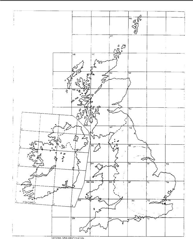
|||||||||||
1,:nsity (Ng) is the number of flashes to ground per |
|||||||||||||
|
|
per |
year. The estimated average annual densities |
stations |
|
|
|||||||
.tr; shown in Fig 6.135. |
|
|
This section is intended to give guidance in the appli- |
||||||||||
|
The effective collection area |
of the structure is the |
cation of weighting and risk factors to power stations. |
||||||||||
area of |
the plan extended in |
all directions to take |
The first step in assessing the requirements for in- |
||||||||||
Jci:ount of its height. For the simple rectangular struc- |
dividual structures must |
be to consider the zone of |
|||||||||||
!ure shown in |
Fig 6.136, the collection area is calculated |
protection afforded by a particular lightning protection |
|||||||||||
iN |
follows: |
||||||||||||
|
|
|
|
|
system. For structures up |
to 20 m high it is reasonable |
|||||||
|
|
|
|
|
|
|
|
|
|
||||
575
Cabling |
Chapter 6 |
|
FIG. 6.135 Number of lightning flashes to the ground per km 2 per year for the UK
to accept that the zone of protection is the volume contained within a 45 ° cone or wedge as shown in Fig 6.138.
This 45 ° cone of protection principle is not considered adequate for structures in excess of 20 m high, since there are many recorded instances of the sides
of tall buildings being struck by lightning. This Phe - nomenon is best explained by considering the process , that precedes a negative downward flash to ground which is the most common type. The lightning flash starts with a step-by-step descent of a downward leader in random steps and with multiple branching. As this
576