

reading / British practice / Vol D - 1990 (ocr) ELECTRICAL SYSTEM & EQUIPMENT
.pdfCable support systems
METRE BETWEEN BRACKETS
mA , BE DECREASED WREN NECESSARY
IC AccommoDATE SPLICE OR TO 55010 j.BRACKETs
NO TE
SIDE kAAy BE In' 455 5CC'"
LADDER RACK TOP ANC BC TTD'm
RACKS ARE nOrnrn
Flu. 6.83 Heavy &ay cable bridge assembly
Fic. 6.84 Cable bridge/tower arrangement
507

Cabling |
Chapter 6 |
|
|
|
|
able. Another variation on the same theme is to mount the towers from the underside of a RSJ using a combination of Cl channels and B15 beam clamps. It is also permissible to fix cable bridges directly to the underside of structural steelwork using the clips described in the previous section. The variety of acceptable fixing arrangements for these box-section bridges all serve to illustrate the overall flexibility provided by the steelwork sysern as a w hole.
Because it is possible to install four 150 mm J- brackets on either side of these bridge sections (for 600 mm wide ladders), it follows that these bridges are capable of carrying significant quantities of cables (up to 112 kg/m). The large quantity of components which need to be assembled to form these cable bridges means that they are a relatively expensive method of supporting cables. It is therefore important to ensure that these bridge/tower arrangements are only specified if they are to be well loaded.
There is, however, a significantly cheaper bridge/ tower combination which may be used for routes with few cables. This is known as the 'tee tower' assembly and it provides a method for supporting a single 300 mm ladder rack laid horizontally over spans of up to 6 m at up to 6 m above the floor. In this arrangement, the towers are formed by bolting together two 300 mm ladders to form a tee-section upright. These ladders are in turn fixed at top and bottom to a special `baseplate' assembly. The 300 mm bridging ladder is then fixed to the top surface of the upper 'baseplate', the cables being cleated to the top of this ladder in the conventional way. Two reinforcing channels are usually fixed to the underside of the horizontal ladder to provide additional rigidity. Where spans of up to 4 in are required, these reinforcing channels are of the Cl pattern, If 6 m spans are required, C2 section channels are used to provide the necessary strength. Despite the relatively long spans and simple tower construction, these tee tower assemblies still have a very high steelwork-to-cable carrying capacity ratio and they are not, therefore, considered to be very cost effective. Alternative cantilever arm based cable support arrangements will therefore be used in preference if fixing positions are available. If the use of a tee tower is unavoidable, then an attempt is always made to open out the support tower pitch to the maximum permissible by using C2 reinforcing channels. A typical tee tower assembly is shown in Fig 6.85.
The tee tower assembly described provides a means for carrying three modules-worth of cables (21 kg/m). Where support for even smaller quantities of cables over elevated routes is required, the cable steelwork system provides small U-brackets which can be bolted directly to Cl and C2 type channel. These U-brackets, illustrated in Fig 6.86, are similar in design to the J-brackets described earlier, consisting essentially of a short length of C3 channel with plates welded to it at either end. A 150 mm wide U-bracket provides the capacity for 14 kg/m of cable whilst 7 kg/m capacity
MAX SPAN Am |
C.2 |
-
MAX
3COTT, , LADDER SACK
WITH CI OR C2 CHAhNEL
REINFORCING
EE TOWERS CONS - R 1,01" .F.D
FROM 3C0mr, LADDER RAC*
FIG. 6.85 Typical tee tower arrangement
FIG. 6.86 U-bracket arrangement
is provided by a 75 mm wide bracket. Overhead cable bridges are formed simply by bolting these U-brackets to lengths of either Cl or C2 channel at 0.6 m intervals. If a Cl channel is used, the maximum permissible span is 4 m, a C2 channel increases this to 6 m. By virtue of the very small cable carrying capacity, this type of cable support arrangement is generally referred to as being 'tail end steelwork' and is used to support cables over the tail ends of their routes as they approach the equipment to which they connect. The important features of tail end steelwork are that:
508

|
|
|
Cable support systems |
|
|
|
|
|
|
|
|
|
|
|
• |
It carries very small quantities of cables. |
• The solid base prevents cables from being routed |
||
out through the bottom of the cable carrier. |
||||
• |
The arrangements used are designed at site, usually |
|||
|
||||
by the cable installation contractor, to suit the phy- |
• The solid base restricts the flow of air round the |
|||
|
sical conditions which prevail where the cable is to |
cables, hence losing a high proportion of the avail- |
||
|
he routed. |
able convective cooling. |
||
|
|
|||
Tai l en d s teelwork does not form part of the com-
•puter matrix used to provide the automatic routing
fac ility. For this reason, tail end steelwork is some- ti mes referred to as 'off matrix steelwork'.
The flexibility provided by the construction kit based , teelwork employed by the CEGB means that there is a v ery large number of tail end steelwork configurations to be found in modern CEGB power stations. The basic cable carriers which are used for tail end
steelwork are:
•J-brackets.
•U-brackets.
•300 mm ladder racks.
•Perforated cable trays.
Of these, the perforated cable tray is the only one kkhich has not been mentioned before. The perforated tray is a proprietary cable support product and is generally of the form illustrated in Fig 6.87. This type of cable support is inexpensive because it has no welds
E:GING SiRIP WHEN REQUIRED
Fin. 6.87 Perforated cable tray
•The upturned lip provides an obstruction to cables leaving the ladder rack.
This subsection has described the various cable steelwork assemblies which are commonly constructed from the basic range of steelwork components. It has illustrated that cable carrying capacity is based around a 7 kg/m 'module' and that standard arrangements are available to support from one to 16 modules of cables. Table 6.22 draws all these standard assemblies together into a single ready-reference chart. A chart such as this would he used by the cable steelwork layout designer when selecting the best type of cable support steelwork for a particular application.
By providing standard support assembly designs, it is possible to draw up a coding system which greatly si mplifies cable steelwork layout drawings. The CEGB uses a coding system based upon the standard assembly figure numbers appearing in GDCD Standard 197 for the preparation of its cable steelwork layout drawings.
6.5 Seismically qualified cable supports
Before leaving the subject of cable support steelwork, it is worth covering briefly the topic of seismic qualification and its impact on cable support steelwork design.
Essentially, seismically qualifying a cable installation requires justification that the cable support steelwork stays intact and in place during the defined seismic incident and also that the cables remain on their support steelwork.
Because of the huge variety of cable steelwork assemblies which will be required for a typical power station cable installation, seismic qualification by full scale test is impractical. By virtue of their frame-like modular construction, cables support steelwork assemblies are most suitable for seismic qualification by mathematical analysis. Complex finite element mathematical computer models are prepared for represen-
construction. ft is also very easy to work with at the very small capacity sizes required for tail end teelwork. Perforated tray steelwork is available in the same sizes as the standard ladder rack, but it is not used in preference to ladder racks where that is Justified because it is inferior to ladder rack on the following counts:
•It has a higher self-weight to cable carrying weight ratio (and is therefore less cost-effective).
•It does not provide convenient cable cleating facilities.
tative or worst-case assemblies in order to predict the behaviour of the real assemblies during the earthquake.
The lengths of channels and the ladder racks are modelled as beam or strut elements whilst the fixings and connections are modelled as translational and/or rotational springs. In many cases, static load testing is used to determine the spring stiffness values for the various connection types.
It is important to realise that the term seismically qualified can only he applied to the cable steelwork assemblies and not the components which go to make up those assemblies. Also, as with the seismic quali-
509
Cabling |
|
|
|
|
|
Chapter 6 |
||
|
|
|
|
|
|
|
|
|
|
|
|
TABLE 6.22 |
|
|
|
|
|
|
|
Guide to selection of steelwork structures for various modules |
|
|
|
|||
|
|
|
|
|
|
|
|
|
|
|
|
Horizontal |
Vertical |
|
|
|
|
|
No. of |
|
|
|
|
|
|
|
|
|
|
Max |
|
Type of |
|
|
|
|
modules |
Maximum |
Type of structure |
|
|
|||
|
|
span |
span |
|
structure |
|
|
|
|
|
|
|
|
||||
|
|
|
|
|
|
|
|
|
|
L p io I |
4 m |
Cl channel — cables laid in channel or |
4 m |
|
CI channel |
|
|
|
|
|
in 75 mm U-bracket |
|
|
|
|
|
|
|
6 m |
C2 channel — cables laid in channel or |
6 m |
|
C2 channel |
|
|
|
|
|
in 75 mm U-bracket |
|
|
|
|
|
|
|
|
|
|
|
|
|
|
|
Up to 2 |
4 m |
Cl channel — cables laid in 150 mm |
4 m |
|
Cl channel |
|
|
|
|
|
U-bracket |
|
|
|
|
|
|
|
6 m |
C2 channel — cables laid in 150 mm |
6 in |
|
C2 channel |
|
|
|
|
|
U-bracket |
|
|
|
|
|
|
|
|
|
|
|
|
|
|
|
Up to 3 |
2 m |
300 mm ladder rack (laid flat) |
|
|
|
|
|
|
|
4 m |
300 mm ladder rack (laid flat) |
|
|
|
|
|
|
|
|
— reinforced with Cl channel |
|
|
|
|
|
|
|
6 m |
300 mm ladder rack (laid flat) |
|
|
|
|
|
|
|
|
— reinforced with C2 channel |
|
|
|
|
|
|
|
|
|
|
|
|
|
|
|
Up to 4 |
2 in |
300 mm ladder rack — on edge with |
1 m |
|
300 mm |
|
|
|
|
|
2 x 150 mm J-brackets |
|
|
cantilever |
|
|
|
|
|
|
|
|
|
|
|
|
Up to 5 |
2 in |
450 mm ladder rack — laid flat |
|
|
|
|
|
|
|
|
|
|
|
|
|
|
|
Up to 6 |
2 m |
450 mm ladder rack — on edge with |
l m |
|
450 mm |
|
|
|
|
|
3 x 150 mm 3-brackets |
|
|
cantilever |
|
|
|
|
|
|
|
|
|
|
|
|
Up to 7 |
2 m |
600 mm ladder rack — laid flat |
|
|
|
|
|
|
|
|
|
|
|
|
|
|
|
Up to 8 |
2 in |
600 mm ladder rack — on edge with |
1 m |
|
600 mm |
|
|
|
|
|
4 x 150 mm 3-brackets |
|
|
cantilever |
|
|
|
|
7.5 m |
300 mm light duty bridge with |
|
|
|
|
|
|
|
|
2 x 150 mm 3-brackets on each side face |
|
|
|
|
|
|
|
9 m |
300 mm heavy duty bridge with |
|
|
|
|
|
|
|
|
2 x 150 mm 3-brackets on each side face |
|
|
|
|
|
|
|
|
|
|
|
|
|
|
|
Up to 12 |
7.5 at |
450 mm light duty bridge with |
|
|
|
|
|
|
|
|
3 x 150 mm J-brackets on each side face |
|
|
|
|
|
|
|
9 m |
450 mm heavy duty bridge with |
|
|
|
|
|
|
|
|
3 x 150 mm I-brackets on each side face |
|
|
|
|
|
|
|
|
|
|
|
|
|
|
|
Up to 16 |
7.5m |
600 mm light duty bridge with |
|
|
|
|
|
|
|
|
4 x 150 mm 3-brackets on each side face |
|
|
|
|
|
|
|
9 m |
600 mm heavy duty bridge with |
|
|
|
|
|
|
|
|
4 x 150 mm 3-brackets on each side face |
|
|
|
|
|
|
|
|
|
|
|
|
|
|
Note: For module requirements greater than those stated in the tab e, use multiples of the system. With 40 modules of cabling use six levels of 600 mm ladder rack on cantilever arms.
fication of other equipment, the seismic qualification will relate to the particular design earthquake conditions being assumed.
For normal non-seismic applications, cable steelwork structures and their fixings have only to be designed to withstand the normal loads imposed by gravity acting on the cables and the self-weight of the structures
themselves. The major difference which needs to be catered for in order to survive a seismic disturbance is resistance to horizontal accelerations. At Heysham 2, which was the first CEGB power station where certain plant items were specifically designed to withstand, the effects of an earthquake of prescribed magnitude the most significant effect on the design of the cable
510

|
|
|
|
|
|
|
|
|
|
|
Cable support systems |
|
|
|
|
|
|
|
|
|
|
|
|
||
steelwork was the increase in the cross-sectional |
The solution, therefore, was to design the floor and |
|||||||||||
areas o f most of the main upright members which, in |
ceiling fixings with pinned |
connections since a true |
||||||||||
urn, increased their stiffness. This effect is seen |
most |
pin connection can transmit no moment. Using these |
||||||||||
Jramatically by the comparison of the floor to ceiling |
fixings led to much lower loadings on the concrete |
|||||||||||
upright members for non-seismic applications with |
anchors and lower stresses in the uprights. The pay-off |
|||||||||||
[ hose for seismic applications (shown in Fig 6.88). The |
from using this fixing method is that it permits greater |
|||||||||||
uprights are shown drawn to the same scale. |
movement in the cable supports. |
|||||||||||
|
|
|
|
|
|
|
|
|
|
The requirement for special civil connections and for |
||
|
|
|
|
|
|
|
|
|
|
large upright sections essentially stemmed from the |
||
|
|
|
|
|
|
|
|
|
|
approach used for seismic qualification at Heysham 2, |
||
|
|
|
|
|
|
|
|
|
|
which was to start with the established format of |
||
|
|
|
|
|
|
|
|
|
|
steelwork and determine what needed to be done to |
||
|
|
|
|
|
|
|
|
|
|
obtain the ability to withstand the seismic disturbance. |
||
|
|
|
|
|
|
|
|
|
|
This approach was adopted for a number of reasons: |
||
|
|
|
|
|
|
|
|
|
|
• The design permitted retention of the cantilever |
||
|
|
|
|
|
|
|
|
|
|
type support arrangements. This in turn enabled the |
||
|
|
|
|
|
|
|
|
|
|
same cable installation practices to be used for the |
||
|
|
|
|
|
|
|
|
|
|
seismically qualified areas of the power station as |
||
|
|
|
|
|
|
|
|
|
|
those used for the non-seismic areas and, as for pre- |
||
|
|
|
|
|
|
|
|
|
|
vious stations, to run the cables out adjacent to the |
||
|
|
|
|
N O N-SE, S MIC |
|
|
route and then lift them into place. |
|||||
|
|
|
|
|
|
|
|
|
||||
|
|
|
|
|
|
|
|
|
|
• Adopting the same basic steelwork format permitted |
||
|
|
|
|
|
|
|
|
|
|
the existing computer-aided cable routing programs |
|
|
|
|
|
|
|
|
|
|
|
|
to be used with very little modification. |
||
|
|
|
|
|
|
|
44 3mm |
• The same cleating methods could be used for both |
||||
|
|
|
|
|
|
|
||||||
|
|
|
|
|
|
|
|
|
|
|||
|
|
|
|
|
|
|
|
|
|
seismic and non-seismic areas. |
|
|
|
|
|
|
|
|
|
|
|
|
|||
|
|
|
|
|
|
|
|
|
|
• Interface compatibility between non-seismic and seis- |
||
|
|
|
|
|
|
|
|
|
|
mic cable steelwork was assured. |
||
|
|
|
|
|
|
|
11 3mm |
00mm |
The decision to employ cantilever type steelwork also |
|||
|
|
|
|
|
|
|
|
|||||
|
|
|
|
|
|
1 |
had penalties, chiefly resulting from the required in- |
|||||
|
|
|
|
|
|
|
|
|
|
|||
|
|
|
|
|
|
|
|
|
|
crease in structure stiffness. The upright members in |
||
|
|
|
|
|
|
|
|
|
|
the support frames became very heavy, expensive, and |
||
|
|
|
|
|
|
|
|
|
|
ti me consuming and labour intensive to install. The |
|
|
|
|
|
|
|
|
|
|
|
|
fixings to the civil structure were also very heavy and |
||
|
|
|
|
|
|
|
41 Irnm |
expensive due to the high load capacities required from |
||||
|
|
|
|
|
|
|
|
|
|
|||
|
|
|
|
|
|
|
|
|
|
them. |
|
|
|
|
|
|
|
|
|
|
|
|
|
|
|
|
|
|
|
|
|
|
|
|
|
The main difficulty arises in accommodating the |
||
|
|
|
|
S EIS M IC |
|
|
|
|
flexibility brought about by the use of the cantilever |
|||
|
|
|
|
|
|
|
|
type cable ladder supports. An alternative approach |
||||
|
|
|
|
|
|
|
|
|
|
|||
|
|
|
|
|
|
|
|
|
|
which is being used at Sizewell B is to use closing |
||
Fir,. 6.88 Comparison of floor to ceiling upright |
|
|
struts to form trapezoidal supports for the cable lad- |
|||||||||
|
|
ders. The effect of adding the closure strut is to pro- |
||||||||||
supports for non-seismic and seismic applications |
|
|
||||||||||
|
|
duce a much stiffer framework as far as horizontal |
||||||||||
|
|
|
|
|
|
|
|
|
|
|||
|
|
|
|
|
|
|
|
|
|
loadings are concerned. The increased stiffness means |
||
Another area of impact on the steelwork was that |
that standard cross-section members can be used, these |
|||||||||||
,11. the civil |
connection design. The high moments |
trapezes usually being assembled using C2 channel. |
||||||||||
generated by |
the horizontal loadings in the steelwork |
Simply adding the closing strut is generally not suffi- |
||||||||||
.memblies led, with conventional fixings, to very high |
cient in its own right to achieve seismic withstand |
|||||||||||
pull - out loads in some of the concrete anchors. In a |
capability, and in many cases additional bracing struts |
|||||||||||
\.onventional |
fixing', it is assumed that the objective |
are needed to achieve the required rigidity. |
||||||||||
ro clamp the steelwork baseplate as rigidly as possible |
The main advantage in going to this system is that |
|||||||||||
[o he floor/ceiling and hence make the connection as |
the frameworks are much easier to handle since they |
|||||||||||
srtr as possible. However, in an assembly where the |
are lighter. Because, in general, they make use of stand- |
|||||||||||
, .ounections at the floor and ceiling are stiff (built-in |
ard components they are also cheaper than their canti- |
|||||||||||
Lon nections), |
much higher stresses in the upright, and |
lever counterparts. The major drawback is of course |
||||||||||
hence greater moments at the fixings, are generated. |
that cable installation is no |
longer straightforward |
||||||||||
511

Cabling |
Chapter 6 |
|
mmEll |
since cables now need to be threaded through the trapezes. The use of trapeze type supports will also mean that for a given cable carrying capacity, the support structure will also occupy a greater volume. This may have implications for civil structure costs for areas such as cable tunnels.
Finally, it is important to appreciate that a seismic withstand requirement will also have an impact on the design and installation of tail end steelwork. The need to demonstrate by mathematical analysis that a cable support will stay intact during an earthquake and the inherent design work and time which this requires, will mean that it is not possible to leave the design of tail end cable steelwork as a site activity. Every tail end steelwork cable support assembly which is required to survive the earthquake must therefore be designed in advance. In order to reduce the costs of this seismic qualification activity, it also becomes necessary to impose limits on the number of designs of tail end steelwork which may be used.
I mposing these limits means that some adaptations of designs may be necessary to suit particular applications at site. This often leads to provision of tail end steelwork with a greater load carrying capacity than required for the application, incurring a hardware cost penalty. This is, of course, offset by the savings which result from not carrying out further qualification analysis. Because of the relative simplicity of the tail end support structures it is, however, possible to use si mplified methods of analysis and thereby produce qualified steelwork designs more cheaply.
7 Cable installation practices
7.1Introduction
This section primarily describes the CEGB's 'cable cleating philosophy' and its origins, i.e., the manner in which cables are permanently located on their support arrangements. As described in the previous section, the bulk of cables in a power station are installed in air on cable supporting steelwork and this is the method on which the most emphasis is placed. The other installation options are:
•Installed direct-in-ground.
•Installed in ducts.
•Laid in concrete troughs.
Before the cables can be permanently cleated to their support steelwork, however, they must first of all be transferred from the drums on which they are delivered to site. This process is known as cable pulling and it is dealt with in Section 7.6 of this chapter.
7.2 The need for cable restraint
The fundamental reason for restraining cables is simply
to provide a means for their location. In the horizontal direction this basically means leading the cables along the correct paths, while vertically it is also necessary t o support their weight. This is true irrespective of th e type and size of cable. There are, however, two further factors which need to be considered when designin g cable cleating arrangements for power cables.
Under normal load conditions, conductor pow er losses dictate that there will be some thermal expan_ sion of the cables and, to allow for this, cables are never anchored to structures as they pass round bends, However, since many power station electrical loads are intermittent there is, in many cases, also an element of thermal cycling which needs to be allowed for by the cleating system used. Over and above these thermal requirements however, there is for the single-core power cables used for large energy transfers across the power station, the need for restraint against the large electromagnetic forces generated under shortcircuit conditions. These large forces do not necessitate cleating of multicore power cables for two reasons:
•Circuits fed using multicore power cables are fuse. protectedand the magnitude of the fault current, and hence the bursting forces generated, are limited by the presence of the fuse.
•Any forces which are generated between the phase conductors are restrained by the construction of the cable itself.
The forces which are exerted on a single-core power cable are negligible under normal full-load conditions (typically I kgf per metre, dependent upon the installation configuration used). Under through-fault conditions, however, forces measured in many thousands of kgf can be generated for periods of the order of I second. The cable restraint system used for single-core power cables must therefore be capable of controlling these forces in order to minimise the risk to human life and damage to adjacent plant and the cables themselves.
For single-core cleat design purposes, a current of 121 kA asymmetric first peak, decaying to 39.4 kA RMS symmetrical in not less than 150 ms is assumed. This is based on a 750 MVA fault on the 11 kV system, reinforced by contributions from rotating plant. Assuming that the main protection functions correctly, then the clearance of that fault will take place within 0.5 seconds. Should main protection fail to operate, the fault will be cleared by the back-up protection but with considerably extended clearance times. However, neither main nor back-up protection operation ti me is used as the design parameter for single-core power cable cleats; instead, the performance capability of the cables themselves is chosen as the limiting factor. The elastomeric cable insulations employed in the CEGB approved range of single-core cables (at all three - auxiliary system voltages), are capable of withstand ing a short-circuit maximum conductor temperature of 250° C. To ensure compatibility with the design Per"
512
|
|
|
|
Cable installation practices |
|
|
|
|
|||
•Irmance of these cables, therefore, the cable cleating |
creases the cable impedance. Installing the cables in |
||||
|
riarvernents are designed to restrain the cables under |
this way will, of course, also take up a greater space on |
|||
lit. |
|
|
the support arrangement. |
||
f,Uilt conditions for the period of time necessary for |
|||||
|
e conductor to reach this limiting temperature. This |
At the moment, CEGB policy accepts that the ad- |
|||
•: i r.; all practical conditions since the cable size will |
vantages of the flat spaced formation outweigh its |
||||
. 0 % c |
been selected to match the system protection |
disadvantages and this is the installation method which |
|||
|
pircinenrs. Putting numbers to this, certain types |
is therefore used. The issue is continually reviewed |
|||
,,:, |
restraints must be capable of withstanding an |
in the light of experience and technological develop- |
|||
|
|
||||
|
[rial shock approaching 9000 kgf on one conductor |
ments in cleat design and it is possible that, in the |
|||
n a,hioned somewhat by the cable itself), and then an |
future, the trefoil group may he favoured for some |
||||
1.. |
latorv load of around 3000 kgf. (Implicit in the |
installations. |
|||
|
|||||
|
ti,ures is an assumption about the formation of |
|
|||
|
cables within the clamps and this point is addressed |
7.4 Cleating philosophy for cables installed |
|||
Luer.) |
|
|
|||
|
|
on steelwork |
|||
|
These short-circuit loading figures are, however, used |
||||
|
design guidelines only. Full scale short-circuit testing |
Both cable type and run orientation will have major |
|||
1 , u sed to demonstrate conclusively the adequacy of a |
|||||
influences on cable cleating philosophy and the CEGB |
|||||
,articular design of cable cleat. |
therefore lays down rules governing cleating arrange- |
||||
|
In summary, therefore, there are three possible rea- |
||||
|
ments for all of the main cable types in the three major |
||||
|
for providing restraint for cables. Which of these |
||||
|
run orientations. These run orientations are: |
||||
. 0116 |
depends upon the cable type being considered. |
||||
j pply |
• Straight horizontal runs with the cables supported |
||||
[ 1 0 „ e |
er, for all cable types, the cleating system used |
||||
li ust provide the most economic method of fulfilling |
on ladder racks. |
||||
:he design functions reliably during the life of the power |
• Straight vertical runs with the cables fixed directly |
||||
s;.iiion. The methods which are used by the CEGB in |
|||||
to cantilever arms. |
|||||
; , ractice are discussed as follows.
• Horizontal runs in a vertical plane (i.e., with the
ladder rack mounted edge-on).
7.3 Cable cleating design parameters
s;inde-core power cables may be installed in either a
. 1rc1oil group' or a 'flat spaced' arrangement. In the ircfoil formation, the three individual phase cables are Jeated together in the form of a triangle, sheath to sheath. in flat formation, as the name implies, the ,,ihIcs are laid side-by-side. In cases where there is a neutral cable, this is either laid alongside the trefoil
:- 1/4mir) or forms a fourth cable in the flat formation.
Hell installation formation has its own advantages ard disadvantages. The trefoil group, because of the
,[() ,e proximity of the conductors, is subject to very i h bursting forces under conditions of through fault
.. ,,irrencs. In addition to this, under normal load con-
.!]:ions, the trefoil arrangement reduces the current
...irr!.ing capacity of the individual cables due to the
- Auced heat radiating surface area. A further dis-
.ki‘antaee is that handling problems make it difficult 'a [a!, up the trefoil arrangement for larger single-core
...ihles. In contrast to this, the flat spaced formation
- ...duces bursting forces considerably, allows full use of :tie .prospective current rating of the cable and is very
•. ;mr )1e to lay. Furthermore, the cleats for the flat spaced :ornialion are of a much simpler pattern than those
,,quired for the trefoil configuration and are therefore 'L•Ns e■pensive.
T he Hat spaced arrangement, however, suffers from
IL
disadvantage of generating a stronger, less homo- := "cous, magnetic field, hence leading to current inahal:ince difficulties in multiconductor per phase circuits and also higher sheath voltages, This effect also in-
Guidelines are also given for cleating at bends, cleating below equipment and for cleating at single-core cable transposition points. These are, however, rather beyond the scope of this text which will therefore only concentrate on the three major groups above. Readers requiring further information on these arrangements should refer to GDCD Standard 216 [21].
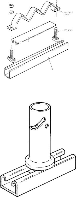
7.4.1 Straight horizontal runs on ladder racks
Single-core power cables are rigidly clamped to the support ladders using plastic coated, steel zig - zag cleats, of the type shown in Fig 6.89, spaced at 1.2 metre intervals (i.e, alternate, upward-facing ladder rungs). A single size of cleat is used for all sizes of cable and the design ensures a centreline spacing of 80 mm. To reduce chafing of the cables due to thermal cycling, a plastic insert is placed into the open face of the ladder rung underneath the cables. Further protection is also provided by the plastic coating of the cleat.
Multicore power cables are installed on ladder racking without clamping hence permitting the required thermal movement to take place. An additional bonus arising from the lack of clamping is that installation costs are also reduced.
In these cases, location is achieved by means of a device known as a thermal spacer. This spacer, shown in Fig 6.90, is a polypropelene peg of 25 mm diameter, with a specially designed foot profile which enables it to be locked firmly into place on a length of cable
513
1PIPP
Cabling |
Chapter 6 |
|
|
|
|
(8) NUT
CQA)
WASHER
CHANNEL INSERT
COVER STRIP
CHANNEL OR LADOER
RACK
Fici, 6.89 Multiple zig-zag cleats for single-core cables
FIG. 6.90 Thermal spacer
support channel, simply by twisting it. These thermal spacers fulfil three functions:
•They provide an easily installed method of restr ai n. ing the lateral movement of cables.
•They provide a simple method of obtaining a 25 m in spacing between adjacent cables to allow air cireui a...
tion, hence avoiding cable derating.
•They provide a simple means of installing the linear
heat detecting cables used for fire detection pu t-. poses in CEGB cable installations. The therm al spacers are locked into place on the underside of the ladder such that the detector cable protects the cables on the ladder immediately below it. The de. tector cables are simply laid into the slot in the barrel of the spacer, some local protection being given to
the detector cable by using a short length of spli t silicon rubber tubing. A longer design of thermal spacer to that shown in Fig 6.90 also exists to support a detector cable above the topmost ladder rack of a stacked arrangement. Further information about the operating principles of linear heat detecting cables can be found in Section 3.8 of this chapter.
Multicore power cables, up to and including 16 mm 2 conductor size, are installed touching in a double-layer located by these thermal spacers along the rails of the ladder work at 1.2 m intervals. Larger cables are installed in a single-layer with a thermal spacer between each cable, hence providing the required air gap (see Fig 6.91).
Control and instrumentation cables require no cooling and hence can be installed touching, irr. -: - ;m:tive
of size (see also Fig 6.91). Again they are ref- |
on |
their support ladders by thermal spacers l.' |
in |
the rails. Cables up to and including 12-core - |
core |
and 60-pair multipair, are installed in a dot |
yer. |
Cable sizes larger than this are installed in |
:gle- |
layer due to their physical size and weigh |
Ihese |
installation rules also serve to limit the amount of combustible mass carried by the ladder rack which is important from the fire propagation point of view.
It is worth noting that where the cable installation is to have a seismic withstand capability, the short, polypropelene thermal spacers are not adequate. Two problems exist:
•The weight and movement of the cables during an earthquake can be such that they can snap the spacers at the narrow part of their foot profile.
•The movement of the cables can be so great that they can jump over the short spacers.
To overcome these problems, the CEGB has developed a special high strength thermal spacer, made from super-tough nylon, which is also twice the height of the standard thermal spacer.
When installing control and instrumentation cables it is also necessary to consider the possibility of adjacent power cables inducing interference currents in
514

Cable installation practices
ZIG-ZAG mULTIPLE CLEAT
ARRANGEMENT 1.
SINGLE CORE POWER CABLES
SINGLE COPE
POWER CABLES
1 200n1m LADDER RACK
ARRANGEMENT2:
MULTICORE POWER CABLES
SHORT THERMAL
SPACERS
MULTICORE POIR
CABLES ISmen
AND BELOW
LADDER RACK
1209mm
MULTICORE POWER,
CABLES ABOVE lEmm.
SHORT THERMAL
SPACERS
|
|
ARRANGEMENT 1: |
|
CONTROL AND |
|
MULTICORE AND |
|
|
MULTIPAIR CONTROL |
||
INSTRUMENTATION |
|
||
LADDER RACK |
CABLES |
||
CAKES |
|||
|
1000mm
FIG. 6.91 Horizontal cable cleating arrangements for multicore power and control cables
he control cores, particularly under fault conditions. io avoid this, the CEGB dictates that, for all major horizontal or vertical cable routes, where power cabling or C and I cabling is run in parallel, a minimum Ph!rsical separation of 600 mrn'is maintained between
the power and control cables. This requirement is relaxed to 300 mm if no single-core power cables follow the route. For ease of installation and cost reduction, this separation ruling is furthermore relaxed at the tail-end of the cable routes for multicore power
515

Cabling |
Chapter 6 |
|
|
cables, provided that the parallel length does not exceed 5 m.
Having separated C and I cables from power cables, it is always considered good practice to install the power cables on the uppermost racks of a stacked array to reduce unnecessary heating, and hence thermal ageing, of the control cables.
7.4.2 Straight vertical runs on cantilever arms
Cantilever arms are installed at 1 m intervals on vertical cable routes and the cables are therefore cleated to every arm.
Zig-zag cleats are not used to anchor single-core cables on vertical runs for two reasons. First, it is not possible to guarantee that the dead weight of the middle cable (or cables if a neutral is present) will be adequately restrained if, for example, the two outside cables in the cleat had slightly larger outside diameters. Secondly, it creates unacceptable installation difficulties in simultaneously lining up three large power cables side-by-side on a vertical run. Instead, individual cast aluminium, two-part claw cleats of the type shown in Fig 6.92 are used in conjunction with a steel bracing
NON MAGNETIC
SPACING STRAP
CLEATS USED IN PAIRS
NOTE DISPOSITION OF CLEATS
SPACING STRAP
FITTED BETWEEN
CLEATS AND ARM
strap to provide rigidity under short-circuit conditions. The cleats are aluminium and not steel in order to avoid the large currents which would circulate in the cleat due to the creation of a magnetic circuit around the cable. The effects are very much smaller where the magnetic circuit loops all three phases of a circuit since a magnetic balance will virtually exist. This is therefore not a problem in the case of the zig-zag cleats used on the horizontal runs. It is for this reason that the bracing strap used with claw cleats must always be placed between the cleats and the cantilever arms rather than above, bridging between the top of the cleats, since the fixing bolts would then create magnetic circuits around the individual cables. These individual claw cleats are, of course, more expensive than the zig-zag cleats and they are also more time consuming to install. They are therefore not used on horizontal cable runs.
Vertical runs of multicore power cables with conductor sizes of above 16 mm 2 are clamped singly, using a single pressed steel cleat of the type shown in Fig 6.93. This type of cleat has the advantage of a specially shaped foot which fixes around the lip profile of the cable support channel. The act of tightening-up the cleat onto the cable serves to lock the cleat in place. This leads to much faster cable installation than using the claw type cleat. A range of cable sizes is covered by one cleat size which is also a major advantage. Such a cleat would not, however, be capable of withstanding the forces associated with a short-circuit and they must not therefore be used for cleating single-core power cables.
Cables of 16 mm 2 conductor size and below are strapped at 1 m intervals in bundles using a specially designed, two part, polypropelene cable tie (similar to conventional cables ties). These ties have specially
:HANNEL NUT
. CHANNEL ARM
MIO 95mm FiXiNG STUD
SECURES EACH PAIR OF
CLEATS AND SPACING
STRAP TO ARM WITH
CHANNEL NUT
EXAMPLE OF USE OF CLEATS FOR 3 SINGLE CORE
POWER CABLES SPACED AT BOrnm CENTRES
SHAPED METAL PLATE TO CLAMP CABLE
ADLILISTED BY SET SCREW
SEPARATE SHAPED PLASTIC COUNTERBED HELD IN POSITION BETWEEN CABLE AND CHANNEL ARM
HOLES FOR MIC |
CLEAT HOOKED ON TO |
FIXING STUD |
|
|
INSIDE OF CHANNEL ARM |
FIG. 6.92 Claw cleats for-single-core cables FEG. 6.93 Pressed steel cleat
516