

reading / British practice / Vol D - 1990 (ocr) ELECTRICAL SYSTEM & EQUIPMENT
.pdfCable types
pruy- Fc TIRE SHEATH
TEMPERATURE SENSITIVE DIELECTRIC MATERIAL
with a continuous conductor temperature of 90 ° C and a short-circuit temperature of 250 ° C, smaller conductor sizes can therefore be used than would be required if PVC insulation were used for the same duty.
For multicore control cables, PVC primary insulation is generally being replaced by a dual layer of EP R/ EVA. The layer of EPR provides the required electrical performance whilst the outer layer of EVA gives sufficient fire performance to pass the test on a single insulated wire, which is detailed in Section 8 of this chapter.
For multipair control cables, the PVC insulation is being replaced by high performance thin-wall insulations such as polyphenol oxide (NORYL — a General Electric (USA) trade name) and poly ether ether ketone (PEEK — an Imperial Chemical Industries trade name). Both these materials are thermoplastic but in the case of PEEK, cables insulated with this material are capable of operating at temperatures in excess of 250 ° C under defined conditions. However, at the time of writing, these materials are considerably more expensive than PVC.
One of the difficulties with these developments is that the material formulations are new and there is little service experience with them compared to PVC which has been used for over thirty years. Therefore it is essential that cables employing such new materials are adequately evaluated before putting them into service; the remaining parts of this section define tests that are used for this purpose.
3.10 Thermal ageing
CROSS SECTION OF
DETECTOR CABLE PROTECTIVE
SHEATH
FIG. 6.11 Analogue-type linear heat detecting cable
propagation performance and reduced gas emissions are given in Section 8 of this chapter.
The basic construction of cables has remained the same but new compounds have been substituted for PVC. For cable beddings and sheaths, currently the inost commonly used replacement for PVC is ethy- lene vinyl acetate copolymer (EVA). EVA is available in both thermoplastic and thermosetting forms. For thermosets, curing can be achieved by continuous vulcanisation by steam or pressurised liquid, and also by immersion in hot water if the silane compound method has been used. These materials are filled with
alurninituirt hydroxide to give reduced fire propagation performance
Whereas PVC has been used in the past for primary insulation on power cables, this is generally being
changed to ethylene propylene rubber (EPR) or cross- linked polythene (XLPE) which has hitherto only been used on single -core power cables. Thermosetting EVA is also being used in some cases for power cable in- sulation. All insulation materials are suitable for use
For normal service life, one of the significant degradation processes in cables is the ageing of their non-metallic materials. It is therefore important to evaluate cables to ensure that they can operate at the required temperature for their service life. For many non-metallic materials the degradation process can be defined by a single temperature-dependent reaction that follows the Arrhenius equation:
(-Ea1'k13T) |
(6.1) |
K = Ae |
|
where K = reaction rate
A = frequency factor
= 2.718
E a = energy needed to activate the degradation reaction (electron volts)
kB = Boltzmann's constant (8.617 x 10 -5 eV/K)
T = absolute temperature, K
This can be transferred into a form which yields an acceleration factor, defined as the service life divided by ageing time, as follows:
443

Cabling |
Chapter 6 |
|
|
|
|
12 |
, C [ - E k E1( 1.11- |
— I 7-1- |
(6.2) |
ti |
|
|
|
where T i |
accelerated ageing temperature, |
K |
|
|
normal service temperature, K |
|
|
tI |
= accelerated ageing time at |
|
|
|
temperature T1, years |
|
|
t2 |
= accelerated ageing time at |
|
|
|
temperature T2, |
years |
|
To apply this formul a, the service temperature and required life of the cable must be defined together with the activation energies of the materials involved. As far as service temperature is concerned, this should be the estimated average service temperature over the life of the cables. For example, cables are generally sized against maximum ambient conditions which allow for peak summer temperatures and the least effective air conditioning. In reality this means that a cable capable of working at a maximum continuous operating temperature of, say, 90 ° C may in fact be operating at an average annual temperature in the order of 75 ° C. Typical mean service temperature conditions are:
• |
Power cables |
— 75 ° C mean. |
|
(90 ° C maximum continuous rating) |
|
• |
Power cables |
— 55 ° C mean. |
|
(70 ° C maximum continuous rating) |
|
• |
Control cables |
— 40° C mean. |
|
( multicore and multipair) |
|
It is normal practice to take the service time as the design life of the power station. This may vary from 25 years to 40 years, or 50 years for hydro stations. It is considered good practice to ignore reduction in service life due to maintenance outages or two - shifting during the later years of conventional plant, as this allows some margin in the predicted life of the cables.
Having defined the service conditions it is now necessary to establish the activation energy of all essential non - metallic materials within the cable. The term essential is used since, for example, some binder tapes are included in cables purely for manufacturing purposes and therefore if they failed mechanically they would not affect service life.
The activation energy of non-metallic materials may be determined by carrying out ageing tests on samples at a number of temperatures. A typical criterion for ageing performance evaluation is to assess the time it takes for the material's 'elongation at break' to reduce to occur at 1.5 times its initial length (50 070 absolute). Dumb-bell samples, of the type shown in Fig 6.12, are therefore used and these are aged in circulating air ovens. Samples are aged at a number of temperatures (say four), these being at least 10 ° C apart and with a maximum temperature of (typically)
|
|
MARKER LINES |
|
|
|
|
lOmm |
|
|
|
|
|
|
|
|
R7 51,m, |
|
|
|
|
|
|
|
|
|
|
|
: |
|
3 5,, |
|
Srnm |
R107/ ! |
|
3mm
50,11
FIG. 6.12 Details of dumb-bell samples
160° C to ensure the degradation mechanism is still representative of that occurring at the service temperature. For some high temperature materials it necessary to exceed 160 ° C to give acceptable testing ti mes, but even then a typical test programme can last up to 2 years. Samples of materials are removed from the ovens until the time is determined at which the material exhibits 50 070 absolute elongation at break. A typical graph of such results is shown in Fig 6.13. From the four test results, a graph of reciprocal temperature against logarithm of time is plotted as shown in Fig 6.14. The Arrhenius activation energy is determined from the slope E a /kB of this graph using the method of least squares. For polymeric cable materials the activation energies are normally in the range of 0.85 and 1.65 eV.
Having established the cable service conditions and material activation energies formula, Equation 6.2) can be used to calculate accelerated ageing time : for test purposes. Typical ageing times for various -:m- peratures and activation energies are shown in Tables 6.3 and 6.4.
From this information, the ageing time and temperature appropriate to the essential cable material having the lowest activation energy can be selected. Actual cable samples are then subjected to this ageing regime after which they are subjected to electrical and mechanical tests to ensure they are still serviceable.
3.11 Mechanical performance
The mechanical properties of cables must be such that they will withstand the rigours of being installed along routes which could consist of horizontal and vertical ladder racks, through ducts and conduits, or direct in the ground. After installation cables must withstand the environmental conditions into which they are placed and these could include damp or oil contaminated situations.
Materials such as PVC and PE have been freely available since the 1950s and therefore the mechanical performance of cables constructed from such materials has been evaluated and proved satisfactory from long
444

Cable types
375
275
250
225
150
1 60 1 C 1 2 153C |
T r 1405C |
25
00
75
50
25
300 |
600 |
300 |
1200 |
1 500 |
1 800 |
|
2100 |
|
|
|
2700 |
|
|
|
|
2400 |
|
3000 |
|||||||||
|
|
|
|
TIME (HOURS) |
|
|
|
|
|
|
|
|
|
FtG. 6.13 Graph of 'elongation at break' plotted against time
TABLE 6.3
Power cable (service life 40 years at 75° C) ageing times at various temperatures
Acti% at ion |
Ageing |
temperature |
Ageing temperature |
energy, CV |
|
I 50 ° C |
135 ° C |
|
|
|
|
1.00 |
40 |
days |
110 days |
120 |
12.5 days |
41 days |
|
1,40 |
4 |
days |
15 days |
1.60 |
1.5 days |
6 days |
|
experience. When introducing new cables into cable construction it is important to evaluate their mechanical properties and the performance of PVC can form a useful benchmark for such tests. Quite clearly the performance of the oversheath is of major importance and therefore the majority of testing must be concerned with evaluating this item.
A typical range of type tests to evaluate mechanical performance includes:
• Abrasion on complete cable.
TABLE 6.4
Control cable (service life 40 years at 40° C) ageing times at various temperatures
etil, ation |
Ageing temperature |
Ageing temperature |
energy, eV |
135 ° C |
115 ° C |
|
|
|
0.85 |
7.5 days |
33 days |
1.00 |
1 day |
11 days |
•Sheath cut-through.
•Crush on complete cable.
•Ozone resistance of insulation and oversheath.
•Water permeation on bedding and oversheath materials.
•Long term water immersion test.
•Mineral oil resistance of oversheath.
•Pulling lubricant resistance of oversheath.
•Tear resistance of oversheath.
1.20 |
3 days |
|
|
1.40 |
1 day |
|
|
|
|
•Retraction of oversheath.
•Hot set on insulation, bedding and oversheath if cross-linked.
445

Cabling |
Chapte |
|
|
I o'
1 03
1 02
21 |
22 |
23 |
24 |
25 |
26 |
27 |
26 |
29 |
z1 0) VT
FIG. 6.14 Arrhenius plot
•Tensile strength and elongation at break on insulation, bedding and oversheath.
•Sheath penetration.
•Hot pressure and hot deformation.
Cut-through, crush, water permeation and tensile strength tests should be carried out on both aged and non-aged samples, the remaining tests being carried out on nonaged samples only.
Many of these tests are covered by British or International Standards such as BS2782, BS6469, IEC 229 and IEC 540, and therefore further details are not included in this volume. However, the cut-through, crush, water immersion, oversheath retraction and penetration tests are less common and further details of these are included.
The cut-through test is designed to measure the capability of the oversheath to withstand being rested on a sharp edge such as that which might occur with a cable tray. This test is performed using a tensile
test machine operating in its compressive mode t, drive a cutting edge (see Fig 6.15) through the Over sheath of a complete cable sample. The force required to achieve this is monitored and compared against the acceptance criteria. The test is carried out at both ambient temperature and the estimated sheath operating temperature. The crush test is similar to the cut. through test, but the cutting edge is replaced by two parallel flat steel blocks 50 mm wide. In this case all metallic components in the cable are monitored and the force required to produce an electrical short is recorded and compared with the acceptance criterion. This test is intended to simulate a cable being crushed by, say, being walked on. The sheath penetration test is designed to simulate a cable being pulled over a sharp edge such as a hexagonal bolt head. In this test a weighted spike is moved along the cable sheath as shown diagrammatically in Fig 6.16. The acceptance
Am, Mint BEFORE
START OF RADIUS
CABLE UNDER TEST
FIG. 6.15 Cut-through test
FIG. 6.16 Sheath penetration test
446
|
|
|
|
|
|
|
|
Power cable system design |
||
|
|
|
|
|||||||
,riterion is based upon a voltage test being applied |
• Bend tests; ambient and cold. |
|||||||||
to he cable sheath although the depth of sheath |
• Voltage withstand; insulation and sheath. |
|||||||||
|
met ration is recorded or information purposes. |
|
|
|
||||||
|
|
• |
|
|
|
• |
Power factor measurement. |
|||
|
|
the oversheath has a considerable impact |
||||||||
Pc Because |
|
|
|
|
|
|
||||
on the ca bl e fire performance, there is a temptation |
• Load cycle (6350/11 000 V and above). |
|||||||||
|
till the oversheath heavily with fire-retardant fillers. |
|||||||||
|
|
|
|
|||||||
|
|
detract from its mechanical performance |
• Partial discharge (6350/11 000 V and above). |
|||||||
and has been found to make materials more suscep- |
||||||||||
• |
I mpulse test. |
|
||||||||
ble to moisture. It is therefore important to carry |
|
|||||||||
:i |
|
|
|
|
|
|
|
|
|
|
out tests to ensure that the oversheath provides ade- |
• Thermal ageing followed by voltage withstand, |
|||||||||
|
me protection against corrosion of the aluminium |
|||||||||
|
|
impulse and partial discharge as appropriate. |
||||||||
o |
|
|
|
|
||||||
or oal ,,anised steel wire armour. It is also considered |
|
|
|
|||||||
essential to specify a long term water immersion test. |
|
|
|
|||||||
Such a test consists of immersing cable samples in |
4 Power cable system design |
|||||||||
|
ater for a period of six months during which the |
|||||||||
|
|
|
|
|||||||
insulation resistance and capacitance of the sheath are |
|
|
|
|||||||
monitored. At the end of the test period the cable |
4.1 Introduction |
|
||||||||
,heaths are subjected to a voltage |
withstand test. This |
|
||||||||
As earlier described, the CEGB has adopted a |
||||||||||
|
is particularly important for single-core cables |
|||||||||
%‘hich may be operated with armouring and, where |
rationalised range of power cable conductor sizes for |
|||||||||
applicable, screens bonded to |
earth at one end of the |
use at each of the three system voltage levels, i.e., |
||||||||
route only. Suitable test voltages are considered to be |
415 V, 3.3 kV and 11 kV. For each feeder or motor |
|||||||||
-WO V AC for single -core cable sheaths and 500 V AC |
circuit application, a suitable conductor size, i.e., cross- |
|||||||||
for the sheaths of all other cable types, the voltages |
sectional area in mm 2 , has to be selected from the |
|||||||||
being applied for I minute. After the voltage tests the |
applicable range. The conductor size chosen is the |
|||||||||
samples are removed from the water and are dissected |
smallest conductor size which meets, as applicable, cer- |
|||||||||
for a visual examination for water ingress or corrosion. |
tain technical requirements. The process of applying |
|||||||||
|
Another test which experience |
has shown to be |
these technical requirements to derive this conductor |
|||||||
\ aluable is one to assess retraction of the oversheath. |
size is called power cable system design. The techni- |
|||||||||
This is necessary to ensure that cable oversheaths do |
cal requirements are primarily concerned with ensuring |
|||||||||
not pull out of the gland seals after |
the installation |
that current and voltage limits are not exceeded. For |
||||||||
clue to thermal cycling. This test is |
therefore only |
current, these are the current carrying capacity or |
||||||||
necessary for power cables. The test procedure requires |
rating of a cable for continuous operation and the |
|||||||||
that a cable sample 10 m long be glanded at each |
magnitude, together with duration, of the current dur- |
|||||||||
end using mechanical glands of the type described in |
ing an overload and a fault. The requirements for |
|||||||||
Section 9.1 of this chapter. The cable sample is laid |
voltage involve the voltage regulation in the cable |
|||||||||
straight and the position of the sheath entry into both |
during normal operation and, where applicable, under |
|||||||||
glands is marked. The cable is then subjected to 40 |
motor starting conditions. |
|
||||||||
load cycles between ambient temperature and its |
|
In fundamental terms, the technical requirements |
||||||||
ma \imum continuous conductor temperature. After |
are based on the need for a cable to have a reasonable |
|||||||||
completion of the load cycles, |
the movement between |
service life, the prevention of thermal damage during |
||||||||
the oversheath and the body of |
the gland, as indicated |
an overload or a fault, and |
safe operation as shown |
|||||||
by |
the reference marks, is measured at both ends. A |
against each requirement in the following: |
||||||||
suitable acceptance criteria is |
considered to be that |
• Current rating for continReasonable service life |
||||||||
the measured values should not exceed 1 mm. |
||||||||||
|
uous operation (including |
|
||||||||
|
|
|
|
|
|
|
|
|
||
|
|
|
|
|
|
|
|
current sharing for single- |
|
|
3.12 Electrical tests |
|
|
|
|
core cables with more |
|
||||
|
|
|
|
than one cable per phase) |
|
|||||
|
|
|
|
|
|
|
|
|
||
Electrical tests can be split into three categories, name- |
• |
Voltage regulation |
Safe or functional |
|||||||
!!, type, routine and site. Details of such tests are |
||||||||||
contained in the relevant International, British, ESI |
|
|
operation |
|||||||
or |
CEGB standards which are referenced in Sections |
• |
Overload current |
Reasonable service life |
||||||
3. ‘ 1 to 3.8 of this chapter. Therefore only a summary |
|
|
and thermal damage |
|||||||
at types of tests that may be employed is given below: |
• |
Short-circuit fault |
Safe operation and |
|||||||
• |
Dimensions. |
|
|
|
||||||
|
|
|
|
(phase to phase) |
thermal damage |
|||||
|
|
|
|
|
|
|
|
|||
• |
Electrical characteristics, i.e., conductor resistance, |
• |
Earth fault |
Safe operation and |
||||||
|
insulation resistance, capacitance, inductance. |
|
|
thermal damage |
||||||
447
Cabling |
Chapter 6 |
|
|
|
|
• |
Sheath voltage |
Safe operation |
|
(single-core cables) |
|
• |
Maximum cable route |
Safe operation and |
|
length (certain types of |
thermal damage |
|
415 V circuits) |
|
Section 4.2 deals w ith the current rating of cables for continuous operation which, for single-core cables, includes the sheath armour voltage with single point bonding and current sharing with more than one cable per phase.
Section 4.3 covers the three types of abnormal condition. These are short-circuit fault, earth fault and overload current, and considers their magnitude and duration relative to cable size for the prevention of thermal damage.
Section 4.4 is a review of motor starting requirements and the determination of motor starting currents and times for different motor sizes.
Section 4.5 deals with the calculation of voltage regulation, i.e., the percentage voltage drop in a supply system due to the impedance of the cables under both steady state and motor starting conditions. The appropriate cable sizes are determined for the voltage regulation limits within which the electrical plant and equipment is specified to operate.
Section 4.6 examines the overall process of power cable system design as applied to feeder and motor circuits. This describes how the various technical requirements are applied at each system voltage level and includes additional requirements specific to certain types of 415 V circuit.
In the final part, the step-by-step procedure followed in selecting a cable size is demonstrated in a number of worked examples.
In practice, the determination of each cable size by calculation is a repetitive and time consuming process. Consequently, tables have been developed for this purpose which enable the correct size to be quickly determined. In the case of continuous current ratings, these allow adjustments to be made for variations in the installation conditions. Some tables, but not all as they are too numerous, are included in the appendices to this chapter.
It is necessary to have available certain design information before the task of power cable system design can commence. This, in turn, calls for the design of the power station electrical auxiliary system and plant layout/nfajor cable routes to be reasonably well advanced. To gain an initial appreciation of what this means, the extent of the design information needed is as follows:
•Types of fault current breaking device and current rating.
•Design load currents for feeder circuits.
•Motor sizes and starting time for large motors.
•Fault levels.
•Protection relay operating times.
•Voltage regulation limits.
•Cable route lengths.
•Types and details of cable routes.
•Ambient temperatures for cables laid in air.
•Soil conditions for buried cables.
•Installation configurations for single-core cables with more than one cable per phase.
In practice, difficulty is usually experienced in obtaining all of this information when cable sizing has to start and therefore assumptions may have to be made in order that the task can proceed.
4.2 Current rating for continuous operation
The maximum or permissible current for continuous (or sustained) AC operation is determined, for a given cable conductor size, by the design of the cable and the conditions under which it is installed.
The principal factors concerned may be summarised
as:
Design of cable
•Conductor material.
•Maximum conductor temperature for insulation.
•Operating voltage.
•Number of load-carrying conductors.
•Cable overall construction. ,
Conditions under which installed
•Ambient temperature.
•Type of cable route.
•Method of installation.
•Method of armour bonding.
The way each of these factors is taken into account can best be described by showing how the permissible current rating of a cable is calculated for the three types of cable route normally employed, i.e., cables laid in air, buried direct in the ground or laid in ducts. As will be seen, this process is solely concerned with ensuring that the temperature of the insulation does not exceed a maximum limit. Each of the above factors is involved with either the determination of the total heat produced within the cable, or affects the way this heat is lost to the surroundings. The current which balances these two during continuous operation at the maximum temperature limit is the permissible current
448
rating of the cable. The following describes in more detail how this current rating is derived.
Maximum conductor temperature
4.2.1
heat is produced in a cable as the result of electrical lo“es due to the flow of current in the metallic components, i.e., conductors, screens and armours, and the presence of voltage. i.e., dielectric losses in the insuIdtion. The hottest part of the cable is the conductor and heat flows outwards to the cable surface to be Liissipated to the surrounding medium by conduction,
nvection and radiation as shown in Fig 6.17,
co If the cable current is steady, the cable temperature riNes above ambient until thermal equilibrium is reached ,,dien the rate at which heat is produced is equal to the rate at which it is lost to the surroundings, as hown for the conductor temperature in Fig 6.18,
Power cable system design
The time taken to reach peak temperature is much shorter for cables laid in air than buried direct in the ground. Typically, for a large size cable, this is 2 - 4 hours when laid in air and in excess of 24 hours when buried direct in the ground.
In Fig 6.18, the equilibrium temperature is just below the cable upper temperature limit, termed the maximum conductor temperature, for continuous operation. The value of this limit is normally determined by the choice of insulation and is derived from consideration of the electrical and mechanical properties of the insulation at the maximum conductor temperature. In particular, these properties must be retained without significant deterioration for a reasonable service life. Softening, leading to thinning of the insulation, during a thermal overload can also be a limiting factor with thermoplastic materials. By international agreement, standard maximum conductor temperatures have
RADIAL HEAT FLOW IS REASONABLY UNIFORM WITHIN THE CABLE BUT is NOT SO EXTERNALLY
CONDUCTOR
INSULATION
BEDDING
/1 ARMOUR
I |
|
OVERSnEATH |
|
1 |
|
I |
1 |
I |
I / 1 |
1 |
|
|
SURROUNDING |
|
MEDIUM |
TEMP
AMBIENT TEMP
DISTANCE FROM CABLE CENTRE
FIG. 6.17 Heat flow in cable
MAX CONDUCTOR TEMP
PEAK TEMPERATURE
CONDUCTOR TEMP RISE
been assigned to all commonly-used insulation types and grades. Examples of these are shown in Table 6.5.
TABLE 6.5
Maximum conductor temperature
|
Insulation |
Maximum conductor |
|
temperature, ° C |
|
AMBIENT TEMP |
|
|
CABLE ENERGISED
TIME
Polyvinyl chloride (PVC) |
70 |
Butyl rubber |
85 |
Ethylene propylene rubber (EPR) |
90 |
Cross-linked polyethylene (XLPE) |
90 |
FiG. 6.18 Conductor temperature rise
449

Cabling |
Chapter 6 |
|
|
4.2.2 Ambient temperature
The conductor equilibrium temperature is equal to the sum of the ambient temperature plus the temperature rise. It therefore follows that before the temperature rise (i.e., current rating) can be determined, the ambient temperature must be known.
The ambient temperature depends on the cable en- vironment, which for cables laid in air is the surrounding air temperature and for cables buried direct in the ground is the soil temperature. Outdoors, the air temperature varies with geographical location, season, ti me of day, etc., which in turn influences the soil temperature. Inside a power station, the air temperature is closely controlled in certain rooms, but elsewhere varies with location from being approximately external air temperature in unheated areas to 50 ° C in parts of a boiler house or nuclear reactor building.
In deciding the value to be adopted, it is not the mean but the highest ambient temperatures that need to be considered if the maximum conductor temperature is not to be exceeded. On this basis, values are selected for each cable environment. For outdoor environments, recommended temperatures are available and these are normally utilised. Typical values for cable ambient temperatures are shown in Table 6.6.
TABLE 6.6
Cable ambient temperatures
|
Environment |
Ambient temperature, |
|
|
° C |
|
Buried in ground |
15 |
|
Laid in ducts |
15 |
|
Outside in air |
25 |
|
Inside in air |
25-50 |
|
|
|
If for a cable laid in air the ambient temperature varies over different portions of the cable route, then clearly the highest ambient temperature involved must be used for cable sizing. With the large number of cables required for a power station, many of which will have parts of their route length at different ambient temperatures, the process of determining the correct ambient temperature for each cable becomes impractical. Therefore a high ambient temperature is adopted which covers all the cables within the power station, except for a few cables in extreme ambient temperature areas such as close to a boiler. These latter cables are easily dealt with separately.
4.2.3 Conductor temperature rise
The steady state conductor temperature rise may be calculated mathematically, enabling the permissible current rating to be determined for a known ambient
and maximum conductor temperature. Account is taken of the heat input from each electrical loss, relative to its position within the cable, and the heat flow through each non-metallic component to the surrounding medium. This treatment is described in IEC287 [II and for AC operation is obtained from the following formula:
(I 2 R |
Wd)Ti [1 2 R (1 |
+ Xi) + W I T |
|
|
chn - 2 |
+ [1 2 R (i + XL + X2) + Wd] n (T3 + 1 4) |
||
where |
= conductor temperature rise above the |
|
|
ambient temperature, |
K |
= current flowing in one conductor, A
R = alternating current resistance per unit length of the conductor at maximum operating temperature, f2/m
Wd = dielectric loss per unit length for the insulation surrounding the conductor, W/m
Ti |
thermal resistance per unit length be- |
|
tween one conductor and the sheath, |
|
K.m/W |
T2 = thermal resistance per unit length of the bedding between sheath and armour, K.m/W
13thermal resistance per unit length of the external serving of the cable, K.m/W
14= thermal resistance per unit length between the cable surface and the surrounding medium, K.m/W
=number of load-carrying conductors in the cable (conductors of equal size and carrying the same load)
X = ratio of losses in the metal sheath to total losses in all conductors in that cable
X2 = ratio of losses in the armouring to total losses in all conductors in that cable
Note: The expression is written in general terms. When applied to polymeric insulated cables, sheath becomes metallic screen (for 11 kV cables in power stations) and external serving becomes oversheath.
The current rating for a four-core low voltage cable may be taken to be equal to the current rating of a three-core cable for the same voltage rating, conductor size and construction when used in a three-phase system with the fourth conductor as neutral.
The dielectric losses (Wd) may be neglected for cables where the voltage between conductors and earth is less than 15 kV for EPR, 37 kV for XLPE and 6 kV for PVC, which is the case for the cables used
450
|
|
|
|
|
|
|
|
|
|
|
|
|
|
Power cable system design |
||||
|
|
|
|
|
|
|
|
|
||||||||||
i n power stations. Simplifying and |
re - arranging to |
currents. Circulating currents occur with solid bonded |
||||||||||||||||
|
|
|
|
cables, i.e., armour bonded to earth at both ends, the |
||||||||||||||
obtain permissible current rating gives: |
|
|
|
|||||||||||||||
|
|
|
|
|
|
|
|
|
|
flow around the armour/earth return loop being in- |
||||||||
|
|
|
|
AO |
|
|
|
|
|
duced by the transformer action between the conductor |
||||||||
|
|
|
|
|
|
|
|
|
and the screen/armour (the screen is bonded to the |
|||||||||
|
|
|
|
|
|
|
|
|
|
|||||||||
|
|
RT1 |
nk ( 1 -" )i2 |
nR (1 + |
4- ”1„.3 |
14) ) 2 |
armour at both ends). Eddy currents are the result of |
|||||||||||
|
|
|
|
|
|
|
|
|
|
dissymmetry in the magnetic field caused by manufac- |
||||||||
it i s appropriate only to describe briefly the |
method |
turing limitations and the installation arrangement. The |
||||||||||||||||
use of non-ferrous metals, i.e., aluminium instead of |
||||||||||||||||||
of calculating each equation component. For |
further |
|||||||||||||||||
[nformation reference should be made to IEC |
287. |
steel wire armour, reduces these |
|
losses. |
||||||||||||||
|
|
|
|
|
|
|
|
|
|
Circulating currents in the armour of single-core |
||||||||
Conductor resistance (R) |
|
|
|
|
|
|
cables can be equal to an appreciable proportion of |
|||||||||||
|
|
|
|
|
|
the conductor current, the magnitude being dependent |
||||||||||||
Conductor resistance for AC operation includes an |
on the load current and the method of installation. |
|||||||||||||||||
allowance for current distortion due to skin and proxi- |
These circulating currents reduce the rating of these |
|||||||||||||||||
mity effects. Skin effect is |
the difference in current |
cables. For example, with 11 kV single-core cables in- |
||||||||||||||||
density between the centre of the conductor |
and the |
stalled in air in flat formation, as described in Section |
||||||||||||||||
conductor surface due to the conductor |
AC magnetic |
4.2.5 of this chapter, the reduction caused by circu- |
||||||||||||||||
field. Proximity effect is the difference in |
current den- |
lating currents is approximately 11 070 for a 300 mm 2 |
||||||||||||||||
si ty due to the interaction of adjacent conductor(s) |
and 17% for a 500 mm 2 size cable. This reduction may |
|||||||||||||||||
and screen/armour AC magnetic fields. |
|
|
|
be avoided by single-point bonding, i.e., bonding the |
||||||||||||||
The AC resistance at maximum operating tempera- |
armour to earth at one end only, which prevents current |
|||||||||||||||||
ture is given by: |
|
|
|
|
|
|
circulating. This, however, induces a standing voltage |
|||||||||||
|
|
|
|
|
|
|
|
|
|
in the cable armour which is at a maximum at the |
||||||||
|
|
|
R = R (1 + |
Yp) |
|
|
|
unearthed end of the cable armour. |
||||||||||
|
|
|
|
|
|
|
|
|
|
With multicore cables, two-core phase and neutral, |
||||||||
where R |
= AC resistance of conductor at maximum |
and three and four core cables carrying a three-phase |
||||||||||||||||
current, the losses are small and have little affect on |
||||||||||||||||||
|
|
|
operating temperature, 12/m |
|
|
|||||||||||||
|
|
|
|
|
rating and are normally only taken into account for |
|||||||||||||
|
|
R' |
DC resistance of conductor at maximum |
|||||||||||||||
|
|
steel wire armoured cables. Multicore cables may there- |
||||||||||||||||
|
|
|
operating temperature, fl/m |
|
|
fore he bonded to earth at both ends without any |
||||||||||||
|
|
Ys |
the skin effect factor |
|
|
|
|
penalty to their rating. |
|
|
|
|||||||
|
|
Yp |
the proximity effect factor |
|
|
|
Thermal resistances of cable components (Ti T2 and |
|||||||||||
|
|
|
|
|
|
|
|
|
|
|||||||||
Both the skin and proximity |
effect factors are small |
T3) |
|
|
|
|
|
|
|
|||||||||
|
|
|
|
|
|
|
|
|||||||||||
for conductor sizes below about 150 mm 2 . |
|
|
To calculate the thermal resistance of the insulation |
|||||||||||||||
The DC resistance at maximum operating tempera- |
(Ti), bedding (T2) and oversheath (T3) the thermal |
|||||||||||||||||
ture is given by: |
|
|
|
|
|
|
resistivity of each component must be known. Thermal |
|||||||||||
|
|
|
|
|
|
|
|
|
|
resistivity is defined as the difference in temperature |
||||||||
|
|
|
R' = R [1 + a 20 (0 — |
20)1 |
|
|
(in kelvin), between opposite faces of a metre cube |
|||||||||||
|
|
|
|
|
|
|
|
|
|
of material caused by the transference of one watt of |
||||||||
where Ro = DC resistance of |
the conductor at 20 ° C, |
heat. In other words, the lower the value of thermal |
||||||||||||||||
|
|
|
12/m |
|
|
|
|
|
|
resistivity the better the material is at transferring heat. |
||||||||
|
|
|
|
|
|
|
|
|
The thermal resistivity values for a number of ma- |
|||||||||
|
|
a zo = constant mass temperature coefficient |
||||||||||||||||
|
|
terials are given in IEC 287, the most commonly used |
||||||||||||||||
|
|
|
at 20 ° C per kelvin (copper = 0.00393, |
are shown in Table 6.7. |
|
|
|
|||||||||||
|
|
|
aluminium = 0.00403) |
|
|
|
|
Using an 11 kV single-core cable as an example, |
||||||||||
0 |
maximum operating temperature, ° C |
the thermal resistance (Ti) between conductor and |
||||||||||||||||
|
|
|
(determined by the type of insulation) |
metallic screen is given by: |
|
|
|
|||||||||||
Appendices A and B list values of AC and DC re- |
T |
1 |
= (Q |
1 |
/27r) x log |
n |
(1 + 2t /d e ) |
|||||||||||
|
|
|
|
|
||||||||||||||
sistance for single -core and multicore power station |
where Qi = thermal resistivity of insulation, |
|||||||||||||||||
cables respectively. |
|
|
|
|
|
|
||||||||||||
K.m/W
Metallic screen and armour loss ratios (X and X2)
Cable metallic screen and armour losses are produced by circulating currents and to a much less extent eddy
dc = diameter of conductor, mm
t = thickness of insulation between conductor and metallic screen, mm
451

IP"
Cabling |
|
Chapter 6 |
|
|
|
TABLE 6.7 |
The thermal resistance T4 is given by: |
|
Values of thermal resistivity for cable materials |
|
|
Material |
Thermal resistivity, K.m/W |
|
|
Insulation |
|
PVC up to 3 kV |
5.0 |
abo%e 3 kV |
6.0 |
EPR up to 3 kV |
3.5 |
above 3 kV |
5.0 |
XLPE |
1.5 |
Butyl rubber |
5,0 |
Sheathing |
|
PVC up to 15 kV |
5.0 |
|
|
Semi-conducting layers are considered part of the insulation. The thermal resistance (T2) between metallic screen and armour is given by:
T2 |
=(QT/27) X log n (1 + 2t2/D 5 ) |
where QT |
thermal resistivity of bedding, K.m/W |
t2 = thickness of bedding, mm
D s = external diameter of metallic screen, mm
The thermal resistance (13) of the oversheath is given
1
T4 —
Deh(&00 7
h — |
|
E |
( D e )g
where D e = external diameter of cable, m
h = heat dissipation coefficient, W/m2 (K)E 25
AOs = excess of cable surface temperature above ambient temperature, K
The heat dissipation factor constants Z, E and g for one, two or three cables either installed spaced or touching, supported away from or cleated direct to a vertical wall, are detailed in IEC 287.
Cables installed outdoors in air are normally shielded from the sun, but if directly exposed, separate calculations must be performed which take account of the heating due to solar radiation.
Cables buried direct in the ground The thermal resistance for a single isolated buried cable is given by:
by: |
|
T3 |
=(@T/27r) x log, (1 + 2t3/D) |
where QT |
thermal resistivity of oversheath, K.m/W |
C3 |
thickness of oversheath, mm |
D'a |
external diameter of the armour, mm |
T4 = (Q T /2r) x log, |
-■/(u 2 — I)] |
where QT = the thermal resistivity of the soil, K.m/W
= 2L/D,
L = distance from the surface of the ground to the cable axis, mm
To calculate the thermal resistance of the insulation for multicore cables reference should be made to IEC
287.
External thermal resistance (Ed
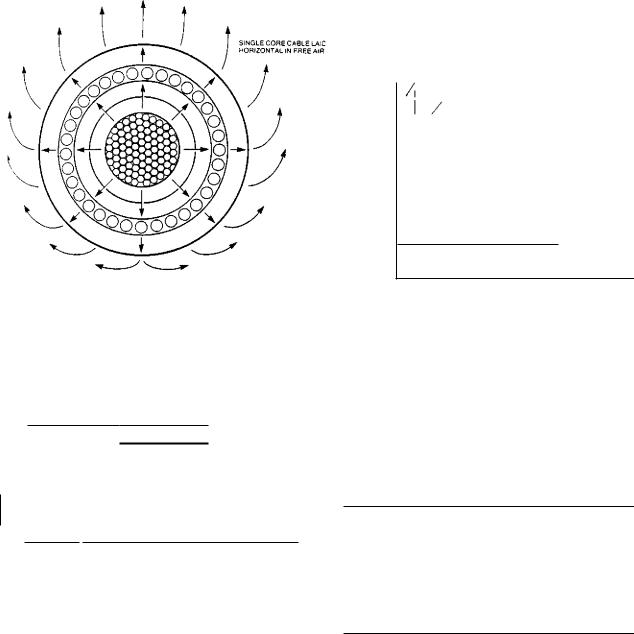
Cables laid in free air (protected from solar radiation) Heat dissipation from an isolated cable laid in free air is mainly by convection, but a proportion will be emitted by radiation to be absorbed by the enveloping surface or transmitted by conduction to the cable support system. In this respect, cables with larger diameters dissipate heat better than smaller cables because of the increased surface area. The close proximity of other cables or a vertical wall reduces heat dissipation. For example, with three single-core cables the heat dissipation and hence current rating is lowest when they are installed in trefoil. The heat dissipation and current rating is improved when the cables are placed in a flat spaced vertical formation and the highest rating is achieved with a flat spaced horizontal formation.
D e = external diameter of cable, mm
The thermal resistivity of the soil depends on the backfill material, degree of compaction, make-up of the original ground and moisture content. Thorough compaction of the backfill material is essential to obtain a satisfactory resistivity. Of the remaining factors, the most important is moisture content which varies the soil thermal resistivity to such an extent that, for most purposes, the effect of soil type can be ignored. This variation is shown in Table 6.8.
At depths of 0.8 m and less, the soil moisture content is dependent on the prevailing weather which varies with geographical location, time of year, etc. Soil thermal resistivity is difficult to measure and for most applications it is convenient to use a standard value representative of the all year round maximum soil thermal resistivity. This condition in average soil (i.e., clay or loam) is when the soil is damp but not quite moist, corresponding to a value of 1.2 K.m/W.
452