


discrete sensors - 4.30
forget to include hard-wired start and stop buttons with an MCR.
L1 |
N |
L1 |
|
PLC |
|
N |
I:0/0 |
|
|
|
Vac |
|
|
|
||
I:0/1 |
|
|
|
O:0/0 |
|
|
|
|
|
I:0/2 |
|
|
|
O:0/1 |
|
|
|
|
|
I:0/3 |
|
|
|
O:0/2 |
|
|
|
|
|
com |
|
|
|
O:0/3 |
|
|
|
||
|
|
|
|
|
4.6 PRACTICE PROBLEM SOLUTIONS
1.capacitive proximity, contact switch, photo-optic retroreflective/diffuse, ultrasonic
2.materials that can be sensed, environmental factors such as dirt, distance to object
3.the sinking output will pass only DC in a single direction, whereas a switch can pass AC and DC.
discrete sensors - 4.31
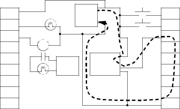
4.
24Vdc |
|
|
|
24Vdc |
|
outputs |
|
+ |
|
inputs |
|
|
|
|
|
||
V+ |
|
24VDC |
|
0 |
|
|
|
- |
|
|
|
0 |
|
|
|
1 |
|
1 |
|
|
|
2 |
|
2 |
|
|
|
3 |
|
3 |
hot |
optical |
V+ |
4 |
|
NPN |
|||||
|
120Vac |
sensor |
|
||
|
PNP |
|
|||
4 |
neut. |
|
5 |
||
|
V- |
||||
|
|
|
|
||
5 |
|
|
|
6 |
|
6 |
|
|
|
7 |
|
7 |
|
|
|
com |
b)the PNP output was selected. because it will supply current, while the input card requires it. The dashed line indicates the current flow through the sensor and input card.
discrete sensors - 4.32
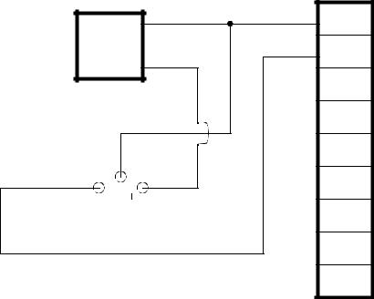
5.
A transparent bottle can be picked up with a capacitive, ultrasonic, diffuse optical sensor. A particular model can be selected at a manufacturers web site (eg., www.banner.com, www.hydepark.com, www.ab.com, etc.) The figure below shows the sensor connected to a sourcing PLC input card - therefore the sensor must be sinking, NPN.
+ |
V+ |
24VDC |
0 |
- |
|
|
1 |
|
2 |
|
3 |
|
4 |
|
5 |
|
6 |
|
7 |
discrete sensors - 4.33
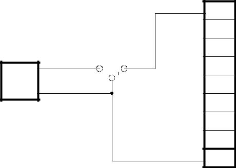
6.
|
00 |
|
|
01 |
|
|
02 |
|
+ |
03 |
|
24VDC |
04 |
|
- |
||
|
||
|
05 |
|
|
06 |
|
|
07 |
|
|
COM |
discrete sensors - 4.34
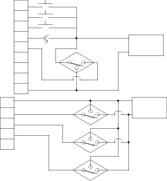
7.
00 |
|
|
01 |
|
|
02 |
|
|
03 |
+ |
power |
|
|
|
04 |
24Vdc supply |
|
|
- |
|
|
|
|
05 |
|
|
06 |
|
|
07 |
|
|
COM |
|
|
V+ |
+ |
power |
|
||
|
24Vdc supply |
|
00 |
|
- |
01 |
|
|
02 |
|
|
03 |
|
|
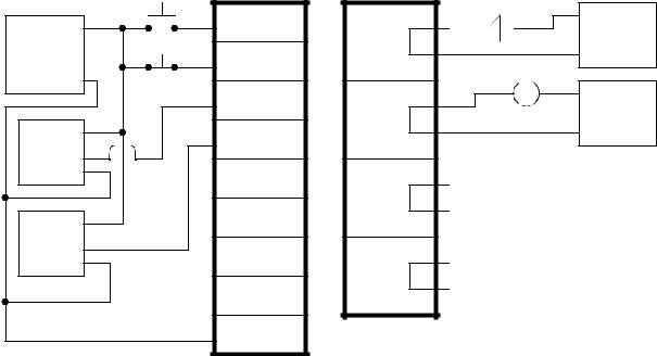
8.
+
power supply
-
V+
PNP
V-
V+
PNP
V-
discrete sensors - 4.35
I:0/0 |
O:0/0 |
+ |
power |
|
|||
|
|
|
|
I:0/1 |
|
- |
supply |
|
|
||
|
|
|
|
I:0/2 |
O:0/1 |
120Vac |
|
|
power |
||
|
|
|
|
|
|
|
supply |
I:0/3 |
|
neut. |
|
|
|
|
|
I:0/4 |
O:0/2 |
|
|
I:0/5 |
|
|
|
I:0/6 |
O:0/3 |
|
|
I:0/7 |
|
|
|
com |
|
|
|