

Instrumentation Sensors Book
.pdfwww.globalautomation.info
Contents |
|
|
xi |
|
|
|
13.5.2 |
Stepper Motors |
228 |
|
|
13.5.3 |
Synchronous Motors |
229 |
13.6 |
Application Considerations |
230 |
||
|
|
13.6.1 |
Valves |
230 |
|
|
13.6.2 |
Power Devices |
231 |
13.7 |
Summary |
231 |
||
|
|
References |
232 |
|
|
|
|
|
|
|
CHAPTER 14 |
|
|
|
|
Programmable Logic Controllers |
233 |
||
14.1 |
Introduction |
233 |
||
14.2 |
Programmable Controller System |
233 |
||
14.3 |
Controller Operation |
235 |
||
14.4 |
Input/Output Modules |
236 |
||
|
|
14.4.1 |
Discrete Input Modules |
236 |
|
|
14.4.2 |
Analog Input Modules |
238 |
|
|
14.4.3 Special Function Input Modules |
238 |
|
|
|
14.4.4 |
Discrete Output Modules |
239 |
|
|
14.4.5 |
Analog Output Modules |
240 |
|
|
14.4.6 |
Smart Input/Output Modules |
240 |
14.5 |
Ladder Diagrams |
243 |
||
|
|
14.5.1 |
Switch Symbols |
243 |
|
|
14.5.2 Relay and Timing Symbols |
244 |
|
|
|
14.5.3 |
Output Device Symbols |
244 |
|
|
14.5.4 |
Ladder Logic |
245 |
|
|
14.5.5 |
Ladder Gate Equivalent |
245 |
|
|
14.5.6 |
Ladder Diagram Example |
246 |
14.6 |
Summary |
249 |
||
|
|
References |
249 |
|
|
|
|
|
|
|
CHAPTER 15 |
|
|
|
|
Signal Conditioning and Transmission |
251 |
||
15.1 |
Introduction |
251 |
||
15.2 |
General Sensor Conditioning |
251 |
||
|
|
15.2.1 Conditioning for Offset and Span |
252 |
|
|
|
15.2.2 Linearization in Analog Circuits |
253 |
|
|
|
15.2.3 |
Temperature Correction |
253 |
|
|
15.2.4 Noise and Correction Time |
255 |
|
15.3 |
Conditioning Considerations for Specific Types of Devices |
255 |
||
|
|
15.3.1 |
Direct Reading Sensors |
255 |
|
|
15.3.2 |
Capacitive Sensors |
255 |
|
|
15.3.3 |
Magnetic Sensors |
256 |
|
|
15.3.4 |
Resistance Temperature Devices |
257 |
|
|
15.3.5 |
Thermocouple Sensors |
259 |
|
|
15.3.6 |
LVDTs |
259 |
|
|
15.3.7 |
Semiconductor Devices |
260 |
15.4 |
Digital Conditioning |
260 |
||
www.globalautomation.info
xii |
|
|
Contents |
|
|
|
15.4.1 Conditioning in Digital Circuits |
260 |
|
15.5 |
Pneumatic Transmission |
261 |
||
|
|
15.5.1 |
Signal Conversion |
261 |
15.6 |
Analog Transmission |
262 |
||
|
|
15.6.1 |
Noise Considerations |
262 |
|
|
15.6.2 |
Voltage Signals |
262 |
|
|
15.6.3 |
Current Signals |
264 |
15.7 |
Digital Transmission |
264 |
||
|
|
15.7.1 |
Transmission Standards |
264 |
|
|
15.7.2 Foundation Fieldbus and Profibus |
265 |
|
15.8 |
Wireless Transmission |
267 |
||
|
|
15.8.1 |
Short Range Protocols |
267 |
|
|
15.8.2 |
Telemetry Introduction |
267 |
|
|
15.8.3 |
Width Modulation |
268 |
|
|
15.8.4 |
Frequency Modulation |
268 |
15.9 |
Summary |
269 |
||
|
|
Definitions |
269 |
|
|
|
References |
270 |
|
|
|
|
|
|
|
CHAPTER 16 |
|
|
|
|
Process Control |
271 |
||
16.1 |
Introduction |
271 |
||
16.2 |
Sequential Control |
271 |
||
16.3 |
Discontinuous Control |
273 |
||
|
|
16.3.1 |
Discontinuous On/Off Action |
273 |
|
|
16.3.2 Differential Closed Loop Action |
273 |
|
|
|
16.3.3 |
On/Off Action Controller |
274 |
|
|
16.3.4 |
Electronic On/Off Controller |
275 |
16.4 |
Continuous Control |
275 |
||
|
|
16.4.1 |
Proportional Action |
276 |
|
|
16.4.2 |
Derivative Action |
278 |
|
|
16.4.3 |
Integral Action |
280 |
|
|
16.4.4 |
PID Action |
281 |
|
|
16.4.5 |
Stability |
284 |
16.5 |
Process Control Tuning |
285 |
||
|
|
16.5.1 |
Automatic Tuning |
286 |
|
|
16.5.2 |
Manual Tuning |
286 |
16.6 |
Implementation of Control Loops |
287 |
||
|
|
16.6.1 On/Off Action Pneumatic Controller |
287 |
|
|
|
16.6.2 |
Pneumatic Linear Controller |
288 |
|
|
16.6.3 Pneumatic Proportional Mode Controller |
289 |
|
|
|
16.6.4 PID Action Pneumatic Controller |
289 |
|
|
|
16.6.5 PID Action Control Circuits |
290 |
|
|
|
16.6.6 |
PID Electronic Controller |
293 |
16.7 |
Summary |
294 |
||
|
|
Definitions |
295 |
|
|
|
References |
296 |
|
www.globalautomation.info
Contents |
|
|
xiii |
|
|
|
|
|
|
|
CHAPTER 17 |
|
|
|
|
Documentation and P&ID |
297 |
||
17.1 |
Introduction |
297 |
||
17.2 |
Alarm and Trip Systems |
297 |
||
|
|
17.2.1 |
Safety Instrumented Systems |
297 |
|
|
17.2.2 Safe Failure of Alarm and Trip |
298 |
|
|
|
17.2.3 Alarm and Trip Documentation |
299 |
|
17.3 |
PLC Documentation |
300 |
||
17.4 |
Pipe and Instrumentation Symbols |
300 |
||
|
|
17.4.1 |
Interconnect Symbols |
301 |
|
|
17.4.2 |
Instrument Symbols |
302 |
|
|
17.4.3 |
Functional Identification |
302 |
|
|
17.4.4 |
Functional Symbols |
304 |
17.5 |
P&ID Drawings |
308 |
||
17.6 |
Summary |
309 |
||
|
|
References |
311 |
|
|
Glossary |
|
313 |
|
|
About the Author |
321 |
||
|
Index |
|
|
323 |
www.globalautomation.info

www.globalautomation.info
Preface
Industrial process control was originally performed manually by operators using their senses of sight and feel, making the control totally operator-dependent. Industrial process control has gone through several revolutions and has evolved into the complex modern-day microprocessor-controlled system. Today’s technology revolution has made it possible to measure parameters deemed impossible to measure only a few years ago, and has made improvements in accuracy, control, and waste reduction.
This reference manual was written to provide the reader with a clear, concise, and up-to-date text for understanding today’s sensor technology, instrumentation, and process control. It gives the details in a logical order for everyday use, making every effort to provide only the essential facts. The book is directed towards industrial control engineers, specialists in physical parameter measurement and control, and technical personnel, such as project managers, process engineers, electronic engineers, and mechanical engineers. If more specific and detailed information is required, it can be obtained from vendor specifications, application notes, and references given at the end of each chapter.
A wide range of technologies and sciences are used in instrumentation and process control, and all manufacturing sequences use industrial control and instrumentation. This reference manual is designed to cover the aspects of industrial instrumentation, sensors, and process control for the manufacturing of a cost-effec- tive, high quality, and uniform end product.
Chapter 1 provides an introduction to industrial instrumentation, and Chapter 2 introduces units and standards covering both English and SI units. Electronics and microelectromechanical systems (MEMS) are extensively used in sensors and process control, and are covered in Chapters 3 through 6. The various types of sensors used in the measurement of a wide variety of physical variables, such as level, pressure, flow, temperature, humidity, and mechanical measurements, are discussed in Chapters 7 through 12. Regulators and actuators, which are used for controlling pressure, flow, and other input variables to a process, are discussed in Chapter 13. Industrial processing is computer controlled, and Chapter 14 introduces the programmable logic controller. Sensors are temperature-sensitive and nonlinear, and have to be conditioned. These sensors, along with signal transmission, are discussed in Chapter 15. Chapter 16 discusses different types of process control action, and the use of pneumatic and electronic controllers for sensor signal amplification and control. Finally, Chapter 17 introduces documentation as applied to instrumentation and control, together with standard symbols recommended by the Instrument Society of America for use in instrumentation control diagrams.
xv
www.globalautomation.info
xvi |
Preface |
Every effort has been made to ensure that the text is accurate, easily readable, and understandable.
Both engineering and scientific units are discussed in the text. Each chapter contains examples for clarification, definitions, and references. A glossary is given at the end of the text.
Acknowledgment
I would like to thank my wife Nadine for her patience, understanding, and many helpful suggestions during the writing of this text.

www.globalautomation.info
C H A P T E R 1
Introduction to Process Control
1.1Introduction
The technology of controlling a series of events to transform a material into a desired end product is called process control. For instance, the making of fire could be considered a primitive form of process control. Industrial process control was originally performed manually by operators. Their sensors were their sense of sight, feel, and sound, making the process totally operator-dependent. To maintain a process within broadly set limits, the operator would adjust a simple control device. Instrumentation and control slowly evolved over the years, as industry found a need for better, more accurate, and more consistent measurements for tighter process control. The first real push to develop new instruments and control systems came with the Industrial Revolution, and World Wars I and II added further to the impetus of process control. Feedback control first appeared in 1774 with the development of the fly-ball governor for steam engine control, and the concept of proportional, derivative, and integral control during World War I. World War II saw the start of the revolution in the electronics industry, which has just about revolutionized everything else. Industrial process control is now highly refined with computerized controls, automation, and accurate semiconductor sensors [1].
1.2Process Control
Process control can take two forms: (1) sequential control, which is an event-based process in which one event follows another until a process sequence is complete; or
(2) continuous control, which requires continuous monitoring and adjustment of the process variables. However, continuous process control comes in many forms, such as domestic water heaters and heating, ventilation, and air conditioning (HVAC), where the variable temperature is not required to be measured with great precision, and complex industrial process control applications, such as in the petroleum or chemical industry, where many variables have to be measured simultaneously with great precision. These variables can vary from temperature, flow, level, and pressure, to time and distance, all of which can be interdependent variables in a single process requiring complex microprocessor systems for total control. Due to the rapid advances in technology, instruments in use today may be obsolete tomorrow. New and more efficient measurement techniques are constantly being introduced. These changes are being driven by the need for higher accuracy,
1
www.globalautomation.info
2 |
Introduction to Process Control |
quality, precision, and performance. Techniques that were thought to be impossible a few years ago have been developed to measure parameters.
1.2.1Sequential Process Control
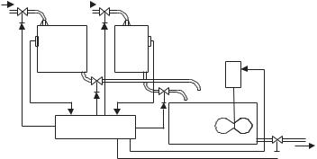
Control systems can be sequential in nature, or can use continuous measurement; both systems normally use a form of feedback for control. Sequential control is an event-based process, in which the completion of one event follows the completion of another, until a process is complete, as by the sensing devices. Figure 1.1 shows an example of a process using a sequencer for mixing liquids in a set ratio [2]. The sequence of events is as follows:
1.Open valve A to fill tank A.
2.When tank A is full, a feedback signal from the level sensor tells the sequencer to turn valve A Off.
3.Open valve B to fill tank B.
4.When tank B is full, a feedback signal from the level sensor tells the sequencer to turn valve B Off.
5.When valves A and B are closed, valves C and D are opened to let measured quantities of liquids A and B into mixing tank C.
6.When tanks A and B are empty, valves C and D are turned Off.
7.After C and D are closed, start mixing motor, run for set period.
8.Turn Off mixing motor.
9.Open valve F to use mixture.
10.The sequence can then be repeated after tank C is empty and Valve F is turned Off.
1.2.2Continuous Process Control
Continuous process control falls into two categories: (1) elementary On/Off action, and (2) continuous control action.
On/Off action is used in applications where the system has high inertia, which prevents the system from rapid cycling. This type of control only has only two states, On and Off; hence, its name. This type of control has been in use for many decades,
Liquid A |
Liquid B |
||
|
|
|
|
Valve A |
Valve B |
|
Liquid |
|
|
|
|
|
|
||
Liquid |
Tank |
Tank |
level B |
|
|
sensor |
Mixer |
||||
level A |
|||||
A |
B |
||||
|
|||||
sensor |
|
|
|||
|
|
|
|
||
|
Valve C |
|
|
|
|
|
|
Valve D |
Tank |
|
|
|
Sequencer |
|
|
||
|
|
C |
|
Mixture out
 Valve F
Figure 1.1 Sequencer used for liquid mixing.
www.globalautomation.info
1.2 Process Control |
3 |
long before the introduction of the computer. HVAC is a prime example of this type of application. Such applications do not require accurate instrumentation. In HVAC, the temperature (measured variable) is continuously monitored, typically using a bimetallic strip in older systems and semiconductor elements in newer systems, as the sensor turns the power (manipulated variable) On and Off at preset temperature levels to the heating/cooling section.
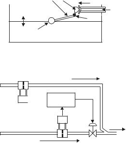
Continuous process action is used to continuously control a physical output parameter of a material. The parameter is measured with the instrumentation or sensor, and compared to a set value. Any deviation between the two causes an error signal to be generated, which is used to adjust an input parameter to the process to correct for the output change. An example of an unsophisticated automated control process is shown in Figure 1.2. A float in a swimming pool is used to continuously monitor the level of the water, and to bring the water level up to a set reference point when the water level is low. The float senses the level, and feedback to the control valve is via the float arm and pivot. The valve then controls the flow of water (manipulated variable) into the swimming pool, as the float moves up and down.
A more complex continuous process control system is shown in Figure 1.3, where a mixture of two liquids is required. The flow rate of liquid A is measured with a differential pressure (DP) sensor, and the amplitude of the signal from the DP measuring the flow rate of the liquid is used by the controller as a reference signal (set point) to control the flow rate of liquid B. The controller uses a DP to measure the flow rate of liquid B, and compares its amplitude to the signal from the DP monitoring the flow of liquid A. The difference between the two signals (error signal) is used to control the valve, so that the flow rate of liquid B (manipulated variable) is directly proportional to that of liquid A, and then the two liquids are combined [3].
Feedback Valve |
Manipulated |
variable (Flow) |
|
Measured |
Fluid in |
variable (Level) |
Pivot |
|
|
Float (Level Sensor) |
|
Figure 1.2 Automated control system.
Liquid A
DP 
 Controller
DP
Mixture out
Liquid B
Figure 1.3 Continuous control for liquid mixing.
www.globalautomation.info
4 |
Introduction to Process Control |
1.3Definition of the Elements in a Control Loop
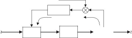
In any process, there are a number of inputs (i.e., from chemicals to solid goods). These are manipulated in the process, and a new chemical or component emerges at the output. To get a more comprehensive look at a typical process control system, it will be broken down into its various elements. Figure 1.4 is a block diagram of the elements in a continuous control process with a feedback loop.
Process is a sequence of events designed to control the flow of materials through a number of steps in a plant to produce a final utilitarian product or material. The process can be a simple process with few steps, or a complex sequence of events with a large number of interrelated variables. The examples shown are single steps that may occur in a process.
Measurement is the determination of the physical amplitude of a parameter of a material; the measurement value must be consistent and repeatable. Sensors are typically used for the measurement of physical parameters. A sensor is a device that can convert the physical parameter repeatedly and reliably into a form that can be used or understood. Examples include converting temperature, pressure, force, or flow into an electrical signal, measurable motion, or a gauge reading. In Figure 1.3, the sensor for measuring flow rates is a DP cell.
Error Detection is the determination of the difference between the amplitude of the measured variable and a desired set reference point. Any difference between the two is an error signal, which is amplified and conditioned to drive a control element. The controller sometimes performs the detection, while the reference point is normally stored in the memory of the controller.
Controller is a microprocessor-based system that can determine the next step to be taken in a sequential process, or evaluate the error signal in continuous process control to determine what action is to be taken. The controller can normally condition the signal, such as correcting the signal for temperature effects or nonlinearity in the sensor. The controller also has the parameters of the process input control element, and conditions the error sign to drive the final element. The controller can monitor several input signals that are sometimes interrelated, and can drive several control elements simultaneously. The controllers are normally referred to as programmable logic controllers (PLC). These devices use ladder networks for programming the control functions.
|
|
Set point |
Error |
|
|
|
|
|
|
Comparator |
|
||
|
Control |
|
signal |
|
||
|
signal |
Controller |
|
Variable |
|
|
|
|
|
|
|
|
|
|
|
|
Feedback signal |
|
amplitude |
|
|
|
|
|
|
|
|
Manipulated |
|
|
|
|
|
Controlled |
variable |
Control |
|
Process |
|
Measuring |
variable |
|
|
|
|
|||
|
element |
|
|
element |
|
|
|
Input |
Output |
|
|||
|
|
|
|
|||
|
|
|
|
|
|
|
Figure 1.4 Block diagram of the elements that make up the feedback path in a process control loop.