

1974 |
CHAPTER 25. ELECTRIC POWER MEASUREMENT AND CONTROL |
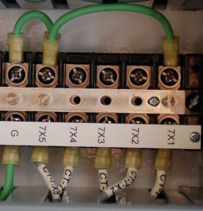
This close-up photograph shows a closed CT test switch equipped with a test jack, the jack’s spring leafs visible as a pair of “hoop” shaped structures flanking the blade of the middle knife switch:
25.6. ELECTRICAL SENSORS |
1975 |
In addition to (or sometimes in lieu of) test switches, current transformer secondary wiring often passes through special “shorting” terminal blocks. These special terminal blocks have a metal “shorting bar” running down their center, through which screws may be inserted to engage with wired terminals below. Any terminals made common to this metal bar will necessarily be equipotential to each other. One screw is always inserted into the bar tapping into the earth ground terminal on the terminal block, thus making the entire bar grounded. Additional screws inserted into this bar force CT secondary wires to ground potential. A photo of such a shorting terminal block is shown here, with five conductors from a multi-ratio (multi-tap) current transformer labeled 7X1 through 7X5 connecting to the terminal block from below:
This shorting terminal block has three screws inserted into the shorting bar: one bonding the bar to the ground (“G”) terminal on the far-left side, another one connecting to the “7X5” CT wire, and the last one connecting to the “7X1” CT wire. While the first screw establishes earth ground potential along the shorting bar, the next two screws form a short circuit between the outer two conductors of the multi-ratio current transformer. Note the green “jumper” wires attached to the top side of this terminal block shorting 7X1 to 7X5 to ground, as an additional measure of safety for this particular CT which is currently unused and not connected to any measuring instrument.
1976 |
CHAPTER 25. ELECTRIC POWER MEASUREMENT AND CONTROL |
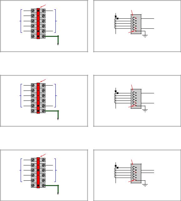
The following illustrations show combinations of screw terminal positions used to selectively ground di erent conductors on a multi-ratio current transformer. The first of these illustrations show the condition represented in the previous photograph, with the entire CT shorted and grounded:
Pictorial representation |
Shorting bar |
|
|
X1 |
|
|
X2 |
|
To current |
X3 |
To protective relay |
transformer |
X4 |
or other instrument |
|
|
|
|
X5 |
|
CT terminals X1 and X5 grounded |
||
CT out of service |
To ground |
|
Schematic representation
Shorting bar
|
X1 |
. . . |
|
Multi-ratio |
X2 |
||
X3 |
To protective relay |
||
current |
|||
X4 |
or other instrument |
||
transformer |
|||
X5 |
. . . |
||
|
|
||
|
Always bonded |
|
|
|
to earth ground |
|
CT terminals X1 and X5 grounded
CT out of service
This next illustration shows how the CT would be used in its full capacity, with X1 and X5 connecting to the panel instrument and (only) X5 grounded for safety:
Pictorial representation |
Shorting bar |
|
|
X1 |
|
|
X2 |
|
To current |
X3 |
To protective relay |
transformer |
X4 |
or other instrument |
|
|
|
|
X5 |
|
CT terminal X5 grounded |
|
|
X1 and X5 in use |
To ground |
|
Schematic representation
Shorting bar
|
X1 |
. . . |
|
Multi-ratio |
X2 |
||
X3 |
To protective relay |
||
current |
|||
X4 |
or other instrument |
||
transformer |
|||
X5 |
. . . |
||
|
|
||
|
Always bonded |
|
|
|
to earth ground |
|
CT terminal X5 grounded
X1 and X5 in use
This final illustration shows how the CT would be used in reduced capacity, with X2 and X3 connecting to the panel instrument and (only) X3 grounded for safety:
Pictorial representation |
Shorting bar |
|
|
X1 |
|
|
X2 |
|
To current |
X3 |
To protective relay |
transformer |
X4 |
or other instrument |
|
|
|
|
X5 |
|
CT terminal X3 grounded |
|
|
X2 and X3 in use |
To ground |
|
Schematic representation
Shorting bar
|
X1 |
. . . |
|
Multi-ratio |
X2 |
||
X3 |
|||
current |
. . . |
||
X4 |
|||
transformer |
To protective relay |
||
X5 |
|||
|
Always bonded |
or other instrument |
|
|
|
||
|
to earth ground |
|
CT terminal X3 grounded
X2 and X3 in use

25.6. ELECTRICAL SENSORS |
1977 |
25.6.6Instrument transformer burden and accuracy
In order for an instrument transformer to function as an accurate sensing device, it must not be unduly tasked with delivering power to a load. In order to minimize the power demand placed on instrument transformers, an ideal voltage-measuring instrument should draw zero current from its PT, while an ideal current-measuring instrument should drop zero voltage across its CT.
The goal of delivering zero power to any instrument is di cult to achieve in practice. Every voltmeter does indeed draw some current, however slight. Every ammeter does drop some voltage, however slight. The amount of apparent power drawn from any instrument transformer is appropriately called burden, and like all expressions of apparent power is measured in units of volt-amps. The greater this burden, the more the instrument transformer’s signal will “sag” (decrease from loading). Therefore, minimizing burden is a matter of maximizing accuracy for power system measurement.
The burden value for any instrument transformer is a function of apparent power, impedance, and either voltage or current according to the familiar apparent power formulae S = VZ2 and S = I2Z:
|
V 2 |
PT burden = |
signal |
Zinstrument |
CT burden = (Isignal2 )(Zinstrument)
Burden for any device or circuit connected to an instrument transformer may be expressed as an impedance value (Z) in ohms, or as an apparent power value (S) in volt-amps. Similarly, instrument transformers themselves are usually rated for the amount of burden they may source and still perform within a certain accuracy tolerance (e.g. ± 1% at a burden of 2 VA).
Potential transformer burden and accuracy ratings
Potential transformers have |
maximum burden values specified in terms of apparent power |
|||
(S,measured in volt-amps), standard burden values being classified by letter code: |
||||
|
|
|
|
|
|
Letter code |
|
Maximum allowable burden at stated accuracy |
|
|
|
|
|
|
|
W |
|
12.5 volt-amps |
|
|
|
|
|
|
|
X |
|
25 volt-amps |
|
|
|
|
|
|
|
M |
|
35 volt-amps |
|
|
|
|
|
|
|
Y |
|
75 volt-amps |
|
|
|
|
|
|
|
Z |
|
200 volt-amps |
|
|
|
|
|
|
|
ZZ |
|
400 volt-amps |
|
|
|
|
|
|
Standard accuracy classes for potential transformers include 0.3, 0.6, and 1.2, corresponding to uncertainties of ± 0.3%, ± 0.6%, and ± 1.2% of the rated turns ratio, respectively. These accuracy class and burden ratings are typically combined into one label. A potential transformer rated “0.6M” therefore has an accuracy of ± 0.6% (this percentage being understood as its turns ratio accuracy) while powering a burden of 35 volt-amps at its nominal (e.g. 120 volts) output.

1978 |
CHAPTER 25. ELECTRIC POWER MEASUREMENT AND CONTROL |
Current transformer burden and accuracy ratings
Current transformer accuracies and burdens are more complicated than potential transformer ratings. The principal reason for this is the wider range of CT application. If a current transformer is to be used for metering purposes (i.e. driving wattmeters, ammeters, and other instruments used for regulatory control and/or revenue billing where high accuracy is required), it is assumed the transformer will operate within its standard rated current values. For example, a 600:5 ratio current transformer used for metering should rarely if ever see a primary current value exceeding 600 amps, or a secondary current exceeding 5 amps. If current values through the CT ever do exceed these maximum standard values, the e ect on regulation or billing will be negligible because these should be transient events. However, protective relays are designed to interpret and act upon transient events in power systems. If a current transformer is to be used for relaying rather than metering, it must reliably perform under overload conditions typically created by power system faults. In other words, relay applications of CTs demand a much larger dynamic range of measurement than meter applications. Absolute accuracy is not as important for relays, but we must ensure the CT will give a reasonably accurate representation of line current during fault conditions in order for the protective relay(s) to function properly. PTs, even those used for protective relaying purposes, never see voltage transients as wide-ranging as the current transients seen by CTs.
Meter class CT ratings typically take the form of a percentage value followed by the letter “B” followed by the maximum burden expressed in ohms of impedance. Therefore, a CT with a metering classification of 0.3B1.8 exhibits an accuracy of ± 0.3% of turns ratio when powering a 1.8 ohm meter impedance at 100% output current (typically 5 amps).
Relay class CT ratings typically take the form of a maximum voltage value dropped across the burden at 20 times rated current (i.e. 100 amps secondary current for a CT with a 5 amp nominal output rating) while maintaining an accuracy within ±10% of the rated turns ratio. Not coincidentally, this is how CT ratios are usually selected for power system protection: such that the maximum expected symmetrical fault current through the power conductor does not exceed 20 times the primary current rating of the CT33. Therefore, a CT with a relay classification of C200 is able to output up to 200 volts while powering its maximum burden at 20× rated current. Assuming a rated output current of 5 amps, 20 times this value would be 100 amps delivered to the relay. If the relay’s voltage drop at this current is allowed to be as high as 200 volts, it means the CT secondary circuit may have an impedance value of up to 2 ohms (200 V ÷ 100 A = 2 Ω). Therefore, a relaying CT rating of C200 is just another way of saying it can power as much as 2 ohms of burden.
The letter “C” in the “C200” rating example stands for calculated, which means the rating is based on theory. Some current transformers use the letter “T” instead, which stands for tested. These CTs have been actually tested at the specified voltage and current values to ensure their performance under real-world conditions.
33For example, in an application where the maximum fault current is expected to be 40,000 amps, we would choose a CT with a ratio of at least 2000:5 to drive the protective relay, because 40,000 amps is twenty times this CT’s primary current rating of 2000 amps. We could also select a CT with a larger ratio such as 3000:5. The point is to have the CT be able to faithfully transform any reasonable fault current into a proportionately lower value for the protective relay(s) to sense.

25.6. ELECTRICAL SENSORS |
1979 |
Current transformer saturation
It is worthwhile to explore the concept of maximum CT burden in some detail. In an ideal world, a CT acts as a current source to the meter or relay it is powering, and as such it is quite content to drive current into a short circuit (0 ohms impedance). Problems arise if we demand the CT to supply more power than it is designed to, which means forcing the CT to drive current through an excessive amount of impedance. In the days of electromechanical meters and protective relays where the devices were entirely powered by instrument transformer signals, the amount of burden imposed by certain meters and relays could be quite substantial34. Modern electronic meters and relays pose much less burden to instrument transformers, approaching the ideal conditions of zero impedance for current-sensing inputs.
The voltage developed by any inductance, including transformer windings, is described by Faraday’s Law of Electromagnetic Induction:
V = N dφdt
Where,
V = Induced voltage (volts) N = Number of turns of wire
dφdt = Rate of change of magnetic flux (Webers per second)
To generate a larger voltage, therefore, a current transformer must develop a faster-changing magnetic flux in its core. If the voltage in question is sinusoidal at a constant frequency, the magnetic flux also traces a sinusoidal function over time, the voltage peaks coinciding with the steepest points on the flux waveform, and the voltage “zero” points coinciding with the peaks on the flux waveform where the rate-of-change of magnetic flux over time is zero:
Voltage reaches its positive peak when the magnetic flux’s rate of change is most positive (i.e. rising quickest)
V φ
Voltage is zero when the magnetic flux’s rate of change is zero (i.e. a "flat" slope)
34An illustrative example to consider is the venerable Westinghouse model CO-11 overcurrent relay, exhibiting a burden of 1.07 volt-amps at a CT secondary current of 5 amps with a 5-amp tap setting. By contrast, an SEL-551 digital overcurrent relay exhibits only 0.16 volt-amps of burden at the same CT current of 5 amps: nearly seven times less burden than the electromechanical relay. The reason for this stark disparity in burden values is the design of each relay: the electromechanical relay demands power from the CT to spin an aluminum disk against the restraining forces of a spring and a drag magnet, while the electronic relay receives operating power from a separate source (station power) and only requires that the CT drive the input of an analog-to-digital converter (ADC) circuit.

1980 |
CHAPTER 25. ELECTRIC POWER MEASUREMENT AND CONTROL |
Imposing a larger burden on a CT (i.e. more impedance the current must drive through) means the CT must develop a larger sinusoidal voltage for any given amount of measured line current. This equates to a flux waveform with a faster-changing rate of rise and fall, which in turn means a higher-peak flux waveform (assuming a sinusoidal shape). The problem with this at some point is that the required magnetic flux reaches such high peak values that the ferrous35 core of the CT begins to saturate with magnetism, at which point the CT ceases to behave in a linear fashion and will no longer faithfully reproduce the shape and magnitude of the power line current waveform. In simple terms, if we place too much burden on a CT it will begin to output a distorted signal no longer faithfully representing line current.
The fact that a CT’s maximum AC voltage output depends on the magnetic saturation limit of its ferrous core becomes particularly relevant to multi-ratio CTs where the secondary winding is provided with more than two “taps”. Multi-ratio current transformers are commonly found as the permanently mounted CTs in the bushings of power transformers, giving the end-user freedom in configuring their metering and protection circuits. Consider this distribution transformer bushing 600:5 CT with a C800 accuracy class rating:
Multi-ratio CT |
Current ratio |
Taps |
|||
|
|
||||
50:5 |
X2-X3 |
||||
|
|
|
|||
(1 turn) |
100:5 |
X1-X2 |
|||
|
|
|
|||
|
|
|
|||
20 turns |
|
X1 |
150:5 |
X1-X3 |
|
|
|||||
|
|
|
|
||
X2 |
200:5 |
X4-X5 |
|||
10 turns |
|
||||
|
|||||
|
|
|
|
||
|
X3 |
250:5 |
X3-X4 |
||
50 turns |
|
||||
|
|||||
|
|
|
|
||
|
X4 |
300:5 |
X2-X4 |
||
40 turns |
|
||||
|
|||||
|
X5 |
400:5 |
X1-X4 |
||
|
|
||||
|
|
||||
|
|
|
450:5 |
X3-X5 |
|
|
|
|
|||
|
|
|
|
|
|
|
|
|
500:5 |
X2-X5 |
|
|
|
|
|
|
|
|
|
|
600:5 |
X1-X5 |
|
|
|
|
|
|
|
This CT’s “C800” classification is based on its ability to source a maximum of 800 volts to a burden when all of its secondary turns are in use. That is to say, its rating is “C800” only when connected to taps X1 and X5 for the full 600:5 ratio. If someone happens to connect to taps X1-X3 instead, using only 30 turns of wire in the CT’s secondary instead of all 120 turns, this CT will be limited to sourcing 200 volts to a burden before saturating: the same magnitude of magnetic flux that could generate 800 volts across 120 turns of wire can only induce one-quarter as much voltage across one-quarter the number of turns, in accordance with Faraday’s Law of Electromagnetic Induction (V = N dφdt ). Thus, the CT must be treated as a “C200” unit when wired for a 150:5 ratio.
35Iron and iron alloys (“ferrous”) reach a point of maximum magnetization where all the magnetic “domains” in a sample are oriented in the same direction, leaving no more left to orient. Once a sample of ferrous material has thus “saturated”, it is of no further benefit to the establishment of a magnetic field. Increases in magnetic force will still produce additional lines of magnetic flux, but not at the rate experienced when the material was not saturated. In other words, a magnetically saturated inductor or transformer core essentially behaves like an air-core inductor or transformer for all additional current values beyond full saturation.
25.6. ELECTRICAL SENSORS |
1981 |
The presence of any direct current in AC power line conductors poses a problem for current transformers which may only be understood in terms of magnetic flux in the CT core. Any direct current (DC) in a power line passing through a CT biases the CT’s magnetic field by some amount, making CT saturate more easily in one half-cycle of the AC than the other. Direct currents never sustain indefinitely in AC power systems, but are often present as transient pulses during certain fault conditions. Even so, transient DC currents will leave CT cores with some residual magnetic bias predisposing them to saturation in future fault conditions. The ability of a CT core to retain some magnetic flux over time is called remanence.
Remanence in a transformer core is an undesirable property. It may be mitigated by designing the core with a air gap (rather than making the core as an unbroken path of ferrous metal), but this compromises other desirable properties such as saturation limits (i.e. maximum output voltage). Some industry experts advise CTs be demagnetized by maintenance personnel as part of the repair work following a high-current fault, in order to ensure optimum performance when the system is returned to service. Demagnetization consists of passing a large AC current through the CT and then slowly reducing the magnitude of that AC current to zero amps. The gradual reduction of alternating magnetic field strength from full to zero tends to randomize the magnetic domains in the ferrous core, returning it to an unmagnetized state.
Whatever the cause, CT saturation can be a significant problem for protective relay circuits because these relays must reliably operate under all manner of transient overcurrent events. The more current through the primary of a CT, the more current it should output to the protective relay. For any given amount of relay burden (relay input impedance), a greater current signal translates into a greater voltage drop and therefore a greater demand for the CT to output a driving voltage. Thus, CT saturation is more likely to occur during overcurrent events when we most need the CT to function properly. Anyone tasked with selecting an appropriate current transformer for a protective relaying application must therefore carefully consider the maximum expected value of overcurrent for system faults, ensuring the CT(s) will do their job while driving the burdens imposed by the relays.
1982 |
CHAPTER 25. ELECTRIC POWER MEASUREMENT AND CONTROL |
Current transformer testing
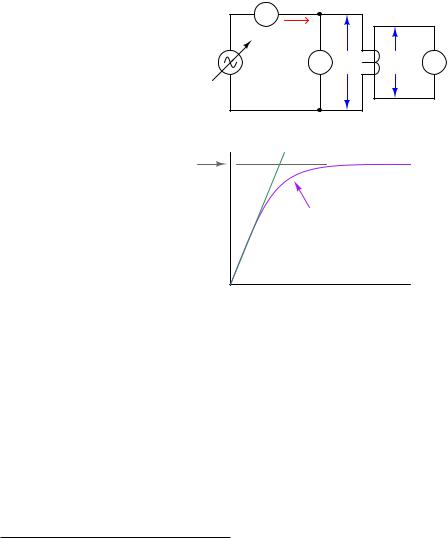
Current transformers may be bench-tested for turns ratio and saturation36 by applying a variable AC voltage to the secondary winding while monitoring secondary current and primary voltage. For common “window” style CTs, the primary winding is a single wire threaded through its center hole. An ideal current transformer would present a constant impedance to the AC voltage source and a constant voltage ratio from input to output. A real current transformer will exhibit less and less impedance as voltage is increased past its saturation threshold:
Testing a CT for ratio and saturation
AC ammeter
|
A |
|
|
IS |
|
Variable AC |
AC V VS |
VP V AC |
voltage source |
||
|
voltmeter |
voltmeter |
Voltage representing max. magnetic flux
Ideal behavior
Saturation
VS |
"Knee point" |
IS
An ideal CT (with no saturation) would trace a straight line. The bent shape reveals the e ects of magnetic saturation, where there is so much magnetism in the CT’s core that additional current only yields miniscule increases in magnetic flux (revealed by voltage drop).
Of course, a CT is never powered by its secondary winding when installed and operating. The purpose of powering a CT “backwards” as shown is to avoid having to drive very high currents through the primary of the CT. If high-current test equipment is available, however, such a primary injection test is actually the most realistic way to test a CT.
36In the electric power industry this is commonly referred to as a “rat/sat” test.

25.6. ELECTRICAL SENSORS |
1983 |
The following table shows actual voltage and current values taken during a secondary excitation test on a C400 class relay CT with a 2000:5 ratio. The source voltage was increased from zero to approximately 600 volts AC at 60 Hz for the test while secondary voltage drop and primary voltage were measured. Around 575 volts a “buzzing” sound could be heard coming from the CT – an audible e ect of magnetic saturation. Calculated values of secondary winding impedance and turns ratio are also shown in this table:
IS |
VS |
VP |
ZS = VS ÷ IS |
Ratio = VS ÷ VP |
0.0308 A |
75.14 V |
0.1788 V |
2.44 kΩ |
420.2 |
|
|
|
|
|
0.0322 A |
100.03 V |
0.2406 V |
3.11 kΩ |
415.8 |
|
|
|
|
|
0.0375 A |
150.11 V |
0.3661 V |
4.00 kΩ |
410.0 |
|
|
|
|
|
0.0492 A |
301.5 V |
0.7492 V |
6.13 kΩ |
402.4 |
|
|
|
|
|
0.0589 A |
403.8 V |
1.0086 V |
6.86 kΩ |
400.4 |
|
|
|
|
|
0.0720 A |
500.7 V |
1.2397 V |
6.95 kΩ |
403.9 |
|
|
|
|
|
0.0883 A |
548.7 V |
1.3619 V |
6.21 kΩ |
402.9 |
|
|
|
|
|
0.1134 A |
575.2 V |
1.4269 V |
5.07 kΩ |
403.1 |
|
|
|
|
|
0.1259 A |
582.0 V |
1.4449 V |
4.62 kΩ |
402.8 |
|
|
|
|
|
0.1596 A |
591.3 V |
1.4665 V |
3.70 kΩ |
403.2 |
|
|
|
|
|
0.2038 A |
600.1 V |
1.4911 V |
2.94 kΩ |
402.5 |
|
|
|
|
|
As you can see from this table, the calculated secondary winding impedance ZS begins to drop dramatically as the secondary voltage exceeds 500 volts (near the “knee” point of the curve). The calculated turns ratio appears remarkably stable – close to the ideal value of 400 for a 2000:5 CT – but one must remember this ratio is calculated on the basis of voltage and not current. Since this test does not compare primary and secondary currents, we cannot see the e ects saturation would have on this CT’s current-sensing ability. In other words, this test reveals when saturation begins to take place, but it does not necessarily reveal how the CT’s current ratio is a ected by saturation.
What makes the di erence between a 2000:5 ratio CT with a relay classification of C400 and a 2000:5 ratio CT with a relay classification of C800 is not the number of turns in the CT’s secondary winding (N )37 but rather the amount of ferrous metal in the CT’s core. The C800 transformer, in order to develop upwards of 800 volts to satisfy relay burden, must be able to sustain twice as much magnetic flux in its core than the C400 transformer, and this requires a magnetic core in the C800 transformer with (at least) twice as much flux-carrying capacity. All other factors being equal, the higher the burden capacity of a CT, the larger and heavier it must be due to the girth of its magnetic core.
37If you think carefully about this, you realize that the number of turns of wire in either CT must be identical, because there is only one “turn” of wire passing through the center of either CT. In order to achieve a 2000:5 ratio, you must have 400 turns of wire wrapped around the toroidal ferrous core per the 1 “turn” of wire passing through the center of that core.
1984 |
CHAPTER 25. ELECTRIC POWER MEASUREMENT AND CONTROL |
Current transformer circuit wire resistance
The burden experienced by an operating current transformer is the total series impedance of the measuring circuit, consisting of the sum of the receiving instrument’s input impedance, the total wire impedance, and the internal secondary winding impedance of the CT itself. Legacy electromechanical relays, with their “operate” coils driven by CT currents, posed significant burden. Since the burden imposed by an electromechanical relay stems from the operation of a wire coil, this burden impedance is a complex quantity having both real (resistive) and imaginary (reactive) components. Modern digital relays with analog-to-digital converters at their inputs generally pose purely resistive burdens to their CTs, and those burden values are generally much less than the burdens imposed by electromechanical relays.
A significant source of burden in any CT circuit is the resistance of the wire carrying the CT’s output current to and from the receiving instrument. It is quite common for the total “loop” distance of a CT circuit to be several hundred feet or more if the CTs are located in remote areas of a facility and the protective relays are located in a central control room. For this reason an important aspect of protective relay system design is wire size (gauge), in order to ensure the total circuit resistance does not exceed the CT’s burden rating.
Larger-gauge wire has less resistance per unit length than smaller-gauge wire, all other factors being equal. A useful formula for approximating the resistance of copper wire is shown here:
R1000f t = e0.232G−2.32
Where,
R1000f t = Approximate wire resistance in ohms per 1000 feet of wire length G = American Wire Gauge (AWG) number of the wire
AWG wire sizes, like most “gauge” scales, is inverse: a larger number represents a thinner wire. This is why the formula predicts a smaller R value for a larger G value. An easy example value to plug into this formula is the number 10 representing #10 AWG wire, a common conductor size for CT secondary circuits:
R1000f t = e(0.232)(10)−2.32
R1000f t = e2.32−2.32
R1000f t = e0 = 1 Ω per 1000 feet
Bear in mind that this result of 1 ohm38 wire resistance per 1000 feet of length applies to the total circuit length, not the distance between the CT and the receiving instrument. A complete CT secondary electrical circuit of course requires two conductors, and so 1000 feet of wire will be needed to cover 500 feet of distance between the CT and the instrument. Some sources cite #12 AWG wire as the minimum gauge to use for CT secondary circuits regardless of wire length.
38Calculations based on the specific resistance of copper at 20 oC place 10 AWG wire at 0.9989 ohms per 1000 feet.
R = ρlA

25.6. ELECTRICAL SENSORS |
1985 |
Example: CT circuit wire sizing, simple
A practical example will help illustrate how wire resistance plays a role in CT circuit performance. Let us begin by considering a C400 accuracy class current transformer to be used in a protective relay circuit, the CT itself possessing a measured secondary winding resistance of 0.3 Ω with a 600:5 turns ratio. By definition, a C400 current transformer is one capable of generating 400 volts at its terminals while supplying 20 times its rated current to a burden. This means the maximum burden value is 4 ohms, since that is the impedance which will drop 400 volts at a secondary current of 100 amps (20 times the CT’s nominal output rating of 5 amps):
C400 current transformer at 20 times rated current, maximum burden value
IP = (20)(600 A) = 12 kA
IS = (20)(5 A) = 100A
 RCT = 0.3 Ω
600:5 ratio |
|
|
|
|
|
|
Vterminal = 400 V |
Max. burden |
|
|
|
|
|
|
|
||||
C400 class |
|
|
|
|
|
|
4 |
Ω |
|
|
|
||||||||
|
|
|
|
|
|
|
|
|
|
|
|
|
|
|
|
|
|
|
|
VW = 430 V
VW = 400 V + (0.3 Ω)(100 A) = 430 V
Although the CT has a C400 class rating which means 400 volts (maximum) produced at its terminals, the winding must actually be able to produce more than 400 volts in order to overcome the voltage drop of its own internal winding resistance. In this case, with a winding resistance of 0.3 ohms carrying 100 amps of current (worst-case), the winding voltage must be 430 volts in order to deliver 400 volts at the terminals. This value of 430 volts, at 60 Hz with a sinusoidal current waveform, represents the maximum amount of magnetic flux this CT’s core can handle while maintaining a current ratio within ± 10% of its 600:5 rating. Thus, 430 volts (inside the CT) is our limiting factor for the CT’s winding at any current value.
This step of calculating the CT’s maximum internal winding voltage is not merely an illustration of how a CT’s “C” class rating is defined. Rather, this is an essential step in any analysis of CT circuit burden because we must know the maximum winding potential the CT is limited to. One might be tempted to skip this step and simply use 400 volts as the maximum terminal voltage during a fault condition, but doing so will lead to minor errors in a simple case such as this, and much more significant errors in other cases where we must de-rate the CT’s winding voltage for reasons described later in this section.

1986 |
CHAPTER 25. ELECTRIC POWER MEASUREMENT AND CONTROL |
Suppose this CT will be used to supply current to a protective relay presenting a purely resistive burden of 0.2 ohms. A system study reveals maximum symmetrical fault current to be 10,000 amps, which is just below the 20× rated primary current for the CT. Here is what the circuit will look like during this fault condition with the CT producing its maximum (internal) voltage of 430 volts:
IP = 10 kA
|
|
|
|
|
|
|
|
|
IS = 10 kA / (600/5) = 83.33 A |
|
||||||
|
|
|
|
|
|
|
|
|
|
|||||||
|
|
|
|
|
||||||||||||
|
|
|
|
|
|
|
|
|
|
|
|
|
|
Protective relay |
||
|
|
|
|
RCT = 0.3 Ω |
Rwire |
|
||||||||||
|
|
|
|
|
||||||||||||
|
|
|
|
|
|
|
|
|||||||||
600:5 ratio |
|
|
|
|
|
|
|
|
|
|
Rrelay = 0.2 |
Ω |
||||
|
|
|
|
|
|
|
|
|
|
|
|
|
||||
|
|
|
|
|
|
|
|
|
|
|
|
|
||||
|
|
|
|
|
|
|
|
|
|
|
|
|
||||
C400 class |
|
|
|
|
|
|
|
|
|
|
|
|
|
|||
|
|
|
|
|
|
|
|
|||||||||
|
|
|
|
|
|
|
|
|
|
|
|
|
|
|
||
|
|
|
|
|
|
|
|
|
|
|
|
|
|
|
|
|
|
|
|
|
|
|
|
|
|
|
|
|
|
|
|
|
|
|
|
|
|
VW = 430 V |
|
|
|
|
|
|
|
|||||
|
|
|
|
|
|
|
|
|
|
|
||||||
|
|
|
|
|
|
|
|
|
|
|
|
|
|
|
|
|
|
|
|
|
|
|
|
|
|
|
|
|
|
|
|
|
|
The CT’s internal voltage limit of 430 volts still holds true, because this is a function of its core’s magnetic flux capacity and not line current. With a power system fault current of 10,000 amps, this CT will only output 83.33 amps rather than the 100 amps used to define its C400 classification. The maximum total circuit resistance is easily predicted by Ohm’s Law, with 430 volts (limited by the CT’s magnetic core) pushing 83.33 amps (limited by the system fault current):
Rtotal = |
VW |
= |
|
430 V |
= 5.16 Ω |
|
If ault |
83.33 A |
|||||
|
|
|
||||
Since we know the total resistance in this series circuit is the sum of CT winding resistance, wire resistance, and relay burden, we may easily calculate maximum wire resistance by subtraction:
Rtotal = RCT + Rwire + Rrelay
Rwire = Rtotal − (RCT + Rrelay )
Rwire = 5.16 Ω − (0.3 Ω + 0.2 Ω) = 4.66 Ω
Thus, we are allowed to have up to 4.66 Ω of total wire resistance in this CT circuit while remaining within the CT’s ratings. Assuming the use of 12 gauge copper wire:
R1000f t = e(0.232)(12)−2.32 = 1.59 Ω per 1000 feet
4.66 Ω
1.59 Ω/1000 ft
= 2.93 × 1000 ft = 2930 ft
Of course, this is total conductor length, which means for a two-conductor cable between the CT and the protective relay the maximum distance will be half as much: 1465 feet.
25.6. ELECTRICAL SENSORS |
1987 |
Example: CT circuit wire sizing, with DC considered
The previous scenario assumes purely AC fault current. Real faults may contain significant DC components for short periods of time, the duration of these DC transients being related to the RL time constant of the power circuit. As previously mentioned, direct current tends to magnetize the ferrous core of a CT, predisposing it to magnetic saturation. Thus, a CT under these conditions will not be able to generate the full AC voltage possible during a controlled bench test (e.g. a C400 current transformer under these conditions will not be able to live up to its 400-volt terminal rating). A simple way to compensate for this e ect is to de-rate the CT’s winding voltage by a factor equal to 1 + XR , the ratio XR being the reactance-to-resistance ratio of the power system at the point of measurement. De-rating the transformer provides a margin of safety for our calculations, anticipating that a fair amount of the CT’s magnetic core capacity may be consumed by DC magnetization during certain faults, leaving less magnetic “headroom” to generate an AC voltage.
Let’s re-do our calculations assuming the power system being protected now has an XR ratio of 14. This means our C400 current transformer (with a maximum internal winding potential of 430 volts) must be “de-rated” to a maximum winding voltage of:
430 V |
= |
|
430 V |
= 28.67 V |
|
|
|
|
|
||
1 + |
X |
1 + 14 |
|||
|
R |
|
|
|
|
If we apply this de-rated winding voltage to the same CT circuit, we find it is insu cient to drive 83.33 amps through the relay:
IP = 10 kA
|
|
IS = 10 kA / (600/5) = 83.33 A |
|
||||||||||||||
|
|
|
|||||||||||||||
|
|
|
|
|
|
|
|
|
|
|
|
|
|
|
Protective relay |
||
|
|
|
|
|
|
|
|
|
|
|
|
|
|
|
|||
|
|
|
|
RCT |
= 0.3 Ω |
Rwire |
|
||||||||||
|
|
|
|
|
|||||||||||||
|
|
|
|
|
|
|
|
||||||||||
600:5 ratio |
|
|
|
|
|
|
|
|
|
|
|
Rrelay = 0.2 |
Ω |
||||
|
|
|
|
|
|
|
|
|
|
|
|
|
|
||||
|
|
|
|
|
|
|
|
|
|
|
|
|
|
||||
|
|
|
|
|
|
|
|
|
|
|
|
|
|
||||
C400 class |
|
|
|
|
|
|
|
|
|
|
|
|
|
|
|||
|
|
|
|
|
|
|
|
|
|||||||||
|
|
|
|
|
|
|
|
|
|
|
|
|
|
|
|
||
|
|
|
|
|
|
|
|
|
|
|
|
|
|
|
|
|
|
|
|
|
|
VW = 28.67 V |
|
|
|
|
|
|
|
||||||
|
|
|
|
|
|
|
|
|
|
|
|||||||
|
|
|
|
|
|
|
|
|
|
|
|
|
|
|
|
|
|
|
|
|
|
|
|
|
|
|
|
|
|
|
|
|
|
|
|
This cannot work! 28.67 volts is not enough to drive 83.33 amps through the circuit even with no wire resistance at all!!
With 0.5 Ω of combined CT and relay resistance (and no wire resistance), a winding voltage of 28.67 volts could only drive 57.33 amps which is far less than we need. Clearly this CT will not be able to perform under fault conditions where DC transients push it closer to magnetic saturation.

1988 |
CHAPTER 25. ELECTRIC POWER MEASUREMENT AND CONTROL |
Upgrading the CT to a di erent model having a higher accuracy class (C800) and a larger current step-down ratio (1200:5) will improve matters. Assuming an internal winding resistance of 0.7 ohms for this new CT, we may calculate its maximum internal winding voltage as follows: if this CT is rated to supply 800 volts at its terminals at 100 amps secondary current through 0.7 ohms of internal resistance, it must mean the CT’s secondary winding internally generates 70 volts more than the 800 volts at its terminals, or 870 volts under purely AC conditions. With our power system’s XR ratio of 14 to account for DC transients, this means we must de-rate the CT’s internal winding voltage from 870 volts to 15 times less, or 58 volts. Applying this new CT to the previous fault scenario:
IP = 10 kA
|
|
|
|
|
|
|
|
|
IS = 10 kA / (1200/5) = 41.67 A |
|
||||||
|
|
|
|
|
|
|
|
|
|
|||||||
|
|
|
|
|
||||||||||||
|
|
|
|
|
|
|
|
|
|
|
|
|
|
Protective relay |
||
|
|
|
|
RCT = 0.7 Ω |
Rwire |
|
||||||||||
|
|
|
|
|
||||||||||||
|
|
|
|
|
|
|
|
|||||||||
1200:5 ratio |
|
|
|
|
|
|
|
|
|
|
Rrelay = 0.2 |
Ω |
||||
|
|
|
|
|
|
|
|
|
|
|
|
|
||||
|
|
|
|
|
|
|
|
|
|
|
|
|
||||
|
|
|
|
|
|
|
|
|
|
|
|
|
||||
C800 class |
|
|
|
|
|
|
|
|
|
|
|
|
|
|||
|
|
|
|
|
|
|
|
|||||||||
|
|
|
|
|
|
|
|
|
|
|
|
|
|
|
||
|
|
|
|
|
|
|
|
|
|
|
|
|
|
|
|
|
|
|
|
|
|
|
|
|
|
|
|
|
|
|
|
|
|
|
|
|
|
VW = 58 V |
|
|
|
|
|
|
|
|||||
|
|
|
|
|
|
|
|
|
|
|
||||||
|
|
|
|
|
|
|
|
|
|
|
|
|
|
|
|
|
|
|
|
|
|
|
|
|
|
|
|
|
|
|
|
|
|
Calculating the allowable total circuit resistance given the new CT’s improved voltage:
Rtotal = |
VW |
= |
58 V |
= 1.392 Ω |
|
41.67 A |
|||
|
If ault |
|
||
Once again, we may calculate maximum wire resistance by subtracting all other resistances from the maximum total circuit resistance:
Rwire = Rtotal − (RCT + Rrelay )
Rwire = 1.392 Ω − (0.7 Ω + 0.2 Ω) = 0.492 Ω
Thus, we are allowed to have up to 0.492 Ω of wire resistance in this circuit while remaining within the CT’s ratings. Using 10 AWG copper wire (exhibiting 1 ohm per 1000 feet), this allows us a total conductor length of 492 feet, which is 246 feet of distance between the CT terminals and the relay terminals.