

15.7. ETHERNET NETWORKS |
1063 |
15.7Ethernet networks
An engineer named Bob Metcalfe conceived the idea of Ethernet in 1973, while working for the Xerox research center in Palo Alto, California. His fundamental invention was the CSMA/CD method of channel arbitration, allowing multiple devices to share a common channel of communication while recovering gracefully from inevitable “collisions.” In Metcalfe’s vision, all of the “network intelligence” would be built directly into “controller” devices situated between the DTE devices (computers, terminals, printers, etc.) and a completely passive coaxial cable network. Unlike some other networks in operation at the time, Metcalfe’s did not rely on additional devices to help coordinate communications between DTE devices. The coaxial cable linking DTE devices together would be completely passive and “dumb,” performing no task but the conduction of broadcast signals between all devices. In that sense, it served the same purpose as the “luminiferous ether” once believed to fill empty space: conducting electromagnetic waves between separated points.
The CSMA/CD (“Carrier Sense Multiple Access with Collision Detection”) method of bus arbitration works by giving each Ethernet device the ability to sense an idle channel as well as sense if it happens to “collide” with another transmitting device. In the event of a collision, the colliding devices both cease transmission, and set random time-delays to wait before re-transmission. The individual time delays are randomized to decrease the probability that a re-collision between the same devices will occur after the wait. This strategy is analogous to several peers in one group holding a conversation, where all people involved are equally free to begin speaking, and equally deferential to their peers if ever two or more accidently begin speaking at the same time. Occasional collisions are perfectly normal in an Ethernet network, and should not be taken as an indication of trouble unless their frequency becomes severe.
Metcalfe’s original network design operated at a data rate of 2.94 Mbps, impressive for its time. By 1980, the three American computer companies DEC (Digital Equipment Corporation), Intel, and Xerox had collaborated to revise the Ethernet design to a speed of 10 Mbps, and released a standard called the DIX Ethernet standard (the acronym “DIX” representing the first letter of each company’s name). Later, the IEEE Local and Metropolitan Networks Standards Committee codified the DIX Ethernet standard under the numeric label 802.3. At the present time there exist many “supplemental” standards underneath the basic 802.3 definition, a few of them listed here:
•802.3a-1985 10BASE2 “thin” Ethernet
•802.3d-1987 FOIRL fiber-optic link
•802.3i-1990 10BASE-T twisted-pair cable Ethernet
•802.3u-1995 100BASE-T “Fast” Ethernet and Auto-Negotiation
•802.3x-1997 Full-Duplex standard
•802.3ab-1999 1000BASE-T “Gigabit” Ethernet over twisted-pair cable
The IEEE 802.3 standard is limited to layers 1 and 2 of the OSI Reference Model: the “Physical” and “Data link” layers. In the physical layer (1), the various supplements describe all the di erent ways in which bits are electrically or optically represented, as well as permissible cable and connector types. In the data link layer (2), the IEEE standard describes how devices are addressed (each one with a unique identifier known as a MAC address, consisting of a 48-bit binary number usually
1064 |
CHAPTER 15. DIGITAL DATA ACQUISITION AND NETWORKS |
divided into six bytes, each byte written as a two-character hexadecimal number), the CSMA/CD channel arbitration protocol, and also how data frames are organized for Ethernet transmissions.
15.7.1Repeaters (hubs)
Bob Metcalfe’s original design for Ethernet consisted of DTE devices connected to a common coaxial cable through the use of “tee” connectors, like this:
|
|
|
|
|
|
|
|
|
|
|
|
|
|
|
|
|
|
Scanner |
|
|
|
|
|
|
|
|
|
|||||
|
|
|
Personal |
|
|
|
|
|
|
|
|
|
|
|
|
|
|
|
|
|
|
|||||||||||
|
|
|
computer |
|
|
|
|
|
|
|
|
|
|
|
|
|
|
|
|
|
|
|
|
|
|
|
|
|||||
Termination |
|
|
|
|
|
|
|
|
|
|
|
|
|
|
|
|
|
|
|
"Stub" or "spur" |
|
|
|
|
Termination |
|||||||
|
|
|
|
|
|
|
|
|
|
|
||||||||||||||||||||||
resistor |
|
|
Coaxial cable |
|
Coaxial cable |
|
|
|
|
|
|
Tee resistor |
||||||||||||||||||||
|
|
|
|
|
|
|
|
|
|
|
|
|
|
|
|
|
|
|
|
|
|
|
|
|
|
|
|
|
|
|
|
|
|
|
|
|
|
|
|
|
|
|
|
|
|
|
|
|
|
|
|
|
|
|
|
|
|
|
|
|
|
|
|
|
|
|
|
Coaxial cable |
|
|
|
|
|
|
|
|
|
|
|
|
|
|
Coaxial cable |
|
|
|
|
|
|
|
||||||||
|
|
Tee |
|
|
|
Tee |
|
|
|
Tee |
|
|
|
|
|
|
|
|||||||||||||||
|
|
|
|
|
|
|
|
|
|
|
|
|
"Stub" or "spur" |
|||||||||||||||||||
|
|
|
|
|
|
|
|
|
|
|
|
|
|
|
|
|
|
|
|
|
|
|
|
|
|
|
|
|
||||
|
|
|
|
|
|
|
|
|
|
|
|
|
|
|
|
|
|
|
|
|
|
|
|
|
|
|||||||
|
|
|
|
|
|
|
|
|
|
|
|
|
|
|
|
|
|
|
|
|
|
|
|
|
|
|
|
|
|
|
|
|
Modem
Printer
(Telecommunications cable)
This cabling arrangement su ered several problems. First, it was inconvenient to run through an o ce building, since each DTE device needed to be coupled rather closely to the main “trunk.” Short cable segments (called stubs, spurs, or drops) joining the main trunk line to each DTE device could not be too long, or else they would could cause multiple signal reflections to occur in the main line. Secondly, the signal strength decreased with each “tee” connector: every time the signal branched, it would lose power. Thirdly, the need for termination resistors at the far ends of the “ether” cable opened up the possibility that those terminators might fail, fall o , or be forgotten during installation or maintenance52.
52These very same problems may arise in FOUNDATION Fieldbus networks, for the exact same reason: the cabling is passive (for increased reliability). This makes FOUNDATION Fieldbus instrument systems challenging to properly install for most applications (except in really simple cases where the cable route is straightforward), which in my mind is its single greatest weakness at the time of this writing (2009). I strongly suspect Ethernet’s history will repeat itself in FOUNDATION Fieldbus at some later date: a system of reliable “hub” devices will be introduced so that these problems may be averted, and installations made much simpler.

15.7. ETHERNET NETWORKS |
1065 |
As Ethernet evolved as a practical networking standard, one of the many improvements added to its design was the concept of a repeating hub. A “repeater” is an active device designed to rebroadcast a signal, usually to overcome inevitable power losses incurred as that signal propagates along a cable. Repeaters are common in the telecommunications industry, where telephone, television, and computer signals must travel hundreds or thousands of miles between points of transmission and reception. A “repeating hub” is a repeater with multiple ports for many cables to plug into, where any signal entering on any cable is repeated to all ports on the device. Thus, a repeating hub (or simply “hub”) allows multiple Ethernet devices to interconnect with no degradation in signal quality:
Personal |
|
Scanner |
computer |
|
|
|
|
|
|
|
|
|
|
|
|
|
|
|
|
Twisted-pair |
|||
Twisted-pair |
|
|
|
|
cable |
||||||
|
|
|
|
||||||||
cable |
|
Hub |
|
|
|
|
|
||||
|
|
|
|
|
|
|
|
|
|
||
|
|
|
|
|
Twisted-pair |
|
|
||||
|
|
|
|
|
|
|
|
|
|
||
Twisted-pair |
|
|
|
|
|
|
cable |
|
|
||
|
|
|
|
|
|
|
|
||||
cable |
|
|
|
|
|
|
|
|
|
|
|
|
|
|
|
|
|
|
|
|
|
|
|
|
|
|
|
|
Power |
|
|
|
|
||
|
Modem |
|
|
Printer |
|||||||
|
|
|
|
|
|
||||||
|
|
|
|
|
|
|
|
|
|
|
|
(Telecommunications cable)
Not only do hubs improve system performance by boosting signals’ voltage levels, but they also eliminate the need for termination resistors in the network. With a hub-based system, each and every cable terminates at either a DTE or DCE device, which is (now) designed with the proper termination resistance built-in to their internal transceiver circuitry. This means each and every Ethernet cable is automatically terminated with the proper impedance simply by plugging it in to the Ethernet port of any device. “Stub” or “spur” cables with their length restrictions are also a thing of the past, since no cable ever splits or branches in a hub-based network system.
Hubs are considered “layer 1” devices, because they operate purely on the physical layer of Ethernet: all they do is receive Ethernet signals and re-broadcast those signals in boosted form to all other devices plugged into the hub. As a piece of interconnecting hardware, a hub is considered a DCE (Data Communications Equipment), as opposed to the end-of-cable devices such as computers and printers which are DTEs (Data Terminal Equipment).
1066 |
CHAPTER 15. DIGITAL DATA ACQUISITION AND NETWORKS |
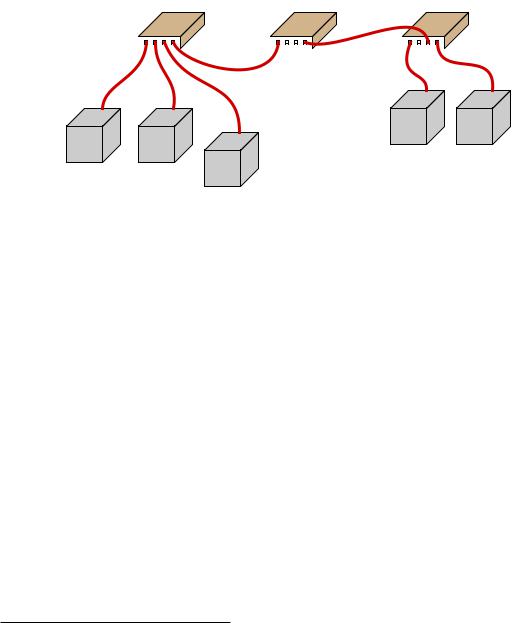
Repeating hubs may be connected together to form larger networks53:
Hub |
Hub |
Hub |
|||
|
|
|
|
|
|
|
|
|
|
|
|
|
|
Ethernet |
Ethernet |
|
|
DTE |
DTE |
Ethernet |
Ethernet |
device |
device |
DTE |
DTE |
|
|
device |
device |
Ethernet |
|
|
|
|
|
|
|
DTE |
|
|
|
device |
|
Since hubs are merely “layer 1” devices, mindlessly boosting and re-broadcasting signals received to their ports, their presence does not mitigate collisions between transmitting devices. As far as collisions between those devices is concerned, they might as well be directly connected together on a single piece of coaxial cable. One way to express this concept is to say that all portions of the network are part of the same collision domain. In other words, any devices on this network are able to collide with each other, because all transmissions are sensed by all the devices. This is analogous to a small room with several people in it: the room is small enough that everyone can hear everyone else talking, which means only one person in that room is able to speak at a time.
53There are practical limits as to how many hubs may be “daisy-chained” together in this manner, just as there are practical limits to how long a twisted-pair cable may be (up to 100 meters). If too many hubs are cascaded, the inevitable time delays caused by the process of repeating those electrical impulses will cause problems in the network. Also, I have neglected to specify the use of crossover cables to connect hubs to other hubs – this is a topic to be covered later in this book!