

774 |
CHAPTER 12. PROGRAMMABLE LOGIC CONTROLLERS |
While the Siemens S7 and Rockwell ControlLogix PLC platforms represent large-scale, modular PLC systems, there exist much smaller PLCs available for a fraction of the cost. Perhaps the least expensive PLC on the market at this time of writing is the Koyo “CLICK” PLC series, the processor module (with eight discrete input and six discrete output channels built in) shown in my hand (sold for 69 US dollars in the year 2010, and with free programming software!):
This is a semi-modular PLC design, with a minimum of input/output (I/O) channels built into the processor module, but having the capacity to accept multiple I/O modules plugged in to the side, much like the Siemens S7-300 PLC.
12.1. PLC EXAMPLES |
775 |
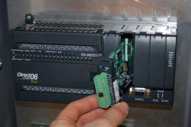
Other semi-modular PLCs expand using I/O cards that plug in to the base unit not unlike traditional rack-based PLC systems. The Koyo DirectLogic DL06 is a good example of this type of semi-modular PLC, the following photograph showing a model DL06 accepting a thermocouple input card in one of its four available card slots:
This photograph shows the PLC base unit with 20 discrete input channels and 16 discrete output channels, accepting an analog input card (this particular card is designed to input signals from thermocouples to measure up to four channels of temperature).
776 |
CHAPTER 12. PROGRAMMABLE LOGIC CONTROLLERS |
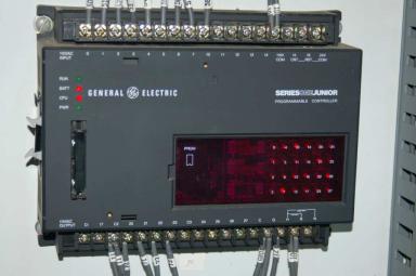
Some low-end PLCs are strictly monolithic, with no ability to accept additional I/O modules. This General Electric Series One PLC (used to monitor a small-scale hydroelectric power generating station) is an example of a purely monolithic design, having no “expansion” slots to accept I/O cards:
A disadvantage of monolithic PLC construction is that damaged I/O cannot be independently replaced. If an I/O channel on one of these PLCs becomes damaged, the entire PLC must be replaced to fix the problem. In a modular system, the damaged I/O card may simply be unplugged from the rack and replaced with a new I/O card. Another disadvantage of monolithic PLCs is the inherently fixed nature of the I/O: the end-user cannot customize the I/O configuration to match the application. For these reasons, monolithic PLCs are usually found on small-scale processes with few I/O channels and limited potential for expansion.

12.2. INPUT/OUTPUT (I/O) CAPABILITIES |
777 |
12.2Input/Output (I/O) capabilities
Every programmable logic controller must have some means of receiving and interpreting signals from real-world sensors such as switches, and encoders, and also be able to e ect control over real-world control elements such as solenoids, valves, and motors. This is generally known as input/output, or I/O, capability. Monolithic (“brick”) PLCs have a fixed amount of I/O capability built into the unit, while modular (“rack”) PLCs use individual circuit board “cards” to provide customized I/O capability.
Monolithic PLC |
Modular ("rack-based") PLC |
X1 |
|
|
|
Y1 |
Power |
Processor |
Input |
|
|
Input |
|
Output |
|
L1 |
|
L2 |
|
|
|
|
0 |
4 |
0 |
4 |
|||
|
supply |
|
|
|
|
1 |
5 |
1 |
5 |
||||
|
|
|
|
|
|
|
2 |
6 |
2 |
6 |
|||
X2 |
|
|
|
Y2 |
|
|
Analog |
|
|
3 |
7 |
3 |
7 |
|
|
|
|
|
|
|
|
|
|
|
|||
|
|
|
|
|
|
|
|
|
|
|
|
||
X3 |
|
|
|
Y3 |
|
|
IN 0+ |
|
|
IN0 |
|
VDC |
|
|
|
|
|
|
IN 0- |
|
|
IN1 |
|
OUT0 |
|
||
|
|
PLC |
|
|
|
|
ANL COM |
|
|
IN2 |
|
OUT1 |
|
X4 |
|
|
Y4 |
|
|
IN 1+ |
|
|
|
|
|||
|
|
|
|
|
IN 1- |
|
|
IN3 |
|
OUT2 |
|
||
X5 |
|
|
|
Y5 |
|
|
ANL COM |
|
|
IN4 |
|
OUT3 |
|
|
|
|
|
|
IN 2+ |
Output |
|
|
|
||||
|
|
|
|
|
|
IN5 |
|
OUT4 |
|
||||
|
|
|
|
|
IN 2- |
|
|
|
|||||
|
|
|
|
|
L1 |
|
0 |
4 |
|
|
|
|
|
X6 |
|
|
|
Y6 |
|
ANL COM |
1 |
5 |
IN6 |
|
OUT5 |
|
|
|
|
|
|
|
IN 3+ |
2 |
6 |
IN7 |
|
OUT6 |
|
||
|
|
|
L2/N |
|
3 |
7 |
|
|
|||||
|
|
Programming |
|
|
|
IN 3- |
|
|
COM |
|
OUT7 |
|
|
Common |
Source |
|
|
ANL COM |
|
|
|
|
|||||
|
Gnd |
|
|
|
|
|
|
|
|||||
port |
|
|
VAC 1 |
|
COM |
|
COM |
|
|||||
|
|
|
|
|
|
|
OUT0 |
|
|
|
|
|
|
|
|
|
|
|
|
|
|
|
|
|
|
|
|
All I/O is fixed in one PLC unit |
|
|
|
OUT1 |
|
|
|
|
|
||||
|
|
|
OUT2 |
|
|
|
|
|
|||||
|
|
|
|
|
|
|
|
OUT3 |
|
|
|
|
|
|
|
|
|
|
Individual cards may be |
VAC 2 |
|
|
|
|
|
||
|
|
|
|
|
OUT4 |
|
|
|
|
|
|||
|
|
|
|
|
removed and replaced |
OUT5 |
|
|
|
|
|
||
|
|
|
|
|
OUT6 |
|
|
|
|
|
|||
|
|
|
|
|
|
|
|
OUT7 |
|
|
|
|
|
The advantages of using replaceable I/O cards instead of a monolithic PLC design are numerous. First, and most obvious, is the fact that individual I/O cards may be easily replaced in the event of failure without having to replace the entire PLC. Specific I/O cards may be chosen for custom applications, biasing toward discrete cards for applications using many on/o inputs and outputs, or biasing toward analog cards for applications using many 4-20 mA and similar signals. Some PLCs even o er the feature of hot-swappable cards, meaning each card may be removed and a new one inserted without de-energizing power to the PLC processor and rack. Please note that one should not assume any system has hot-swappable cards, because if you attempt to change out a card “live” in a system without this feature, you run the risk of damaging the card and/or the rest of the unit it is plugged in to!
778 |
CHAPTER 12. PROGRAMMABLE LOGIC CONTROLLERS |
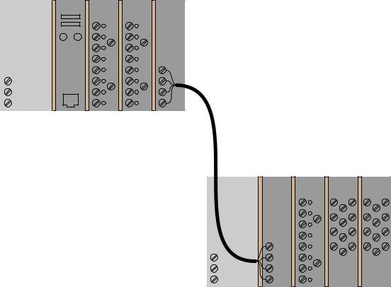
Some PLCs have the ability to connect to processor-less remote racks filled with additional I/O cards or modules, thus providing a way to increase the number of I/O channels beyond the capacity of the base unit. The connection from host PLC to remote I/O racks usually takes the form of a special digital network, which may span a great physical distance:
Power |
Processor |
Digital |
Digital |
Remote |
|
inputs |
outputs |
I/O |
|
supply |
|
|||
|
|
|
interace |
|
L1 |
|
|
|
|
L2/N |
|
|
|
|
Gnd |
|
|
|
|
Host PLC (base unit)
Network
cable
Remote I/O rack
Power |
Remote |
Digital |
Analog |
Analog |
|
I/O |
outputs |
inputs |
outputs |
||
supply |
|||||
interace |
|
|
|
||
L1 |
|
|
|
|
|
L2/N |
|
|
|
|
|
Gnd |
|
|
|
|
An alternative scheme for system expansion is to network multiple PLCs together, where each PLC has its own dedicated rack and processor. Through the use of communication instructions, one PLC may be programmed to read data from and/or write data to another PLC, e ectively using the other PLC as an extension of its own I/O. Although this method is more expensive than remote I/O (where the remote racks lack their own dedicated processors), it provides the capability of stand-alone control in the event the network connection between PLC processors becomes severed.
Input/output capability for programmable logic controllers comes in three basic varieties: discrete, analog, and network ; each type discussed in a following subsection.
12.2. INPUT/OUTPUT (I/O) CAPABILITIES |
779 |
12.2.1Discrete I/O
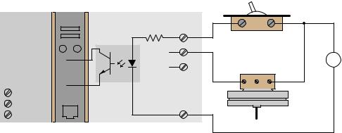
A “discrete” data point is one with only two states on and o . Process switches, pushbutton switches, limit switches, and proximity switches are all examples of discrete sensing devices. In order for a PLC to be aware of a discrete sensor’s state, it must receive a signal from the sensor through a discrete input channel. Inside each discrete input module is (typically) a set of light-emitting diodes (LEDs) which will be energized when the corresponding sensing device turns on. Light from each LED shines on a photo-sensitive device such as a phototransistor inside the module, which in turn activates a bit (a single element of digital data) inside the PLC’s memory. This opto-coupled arrangement makes each input channel of a PLC rather rugged, capable of isolating the sensitive computer circuitry of the PLC from transient voltage “spikes” and other electrical phenomena capable of causing damage:
|
|
PLC |
Hand switch |
|
|
|
|
|
|
|
|
|
|
Power |
Processor |
Discrete input card (DC sinking) |
|
|
|
|
|
|
|
|
|
||
supply |
|
Ch1 |
|
|
|
|
|
|
|
|
|
|
|
|
|
Optocoupler |
|
|
|
|
|
|
... Ch2 |
|
|
+ |
DC power |
|
|
... Ch3 |
Pressure switch |
− |
supply |
|
|
|
|
|
|
||
|
|
|
NO |
NC Com |
|
|
L1 |
|
|
|
|
|
|
L2/N |
|
|
|
|
|
|
Gnd |
|
Com |
|
|
|
|
|
|
|
|
|
|
|
Energizing an input channel lights the LED inside the optocoupler, turning on the phototransistor, sending a "high" signal to the PLC’s microprocessor, setting (1) that bit in the PLC’s input register.
The internal schematic diagram for a discrete input module (“card”) shown above reveals the componentry typical for a single input channel on that card. Each input channel has its own optocoupler, writing to its own unique memory register bit inside the PLC’s memory. Discrete input cards for PLCs typically have 4, 8, 16, or 32 channels.
780 |
CHAPTER 12. PROGRAMMABLE LOGIC CONTROLLERS |
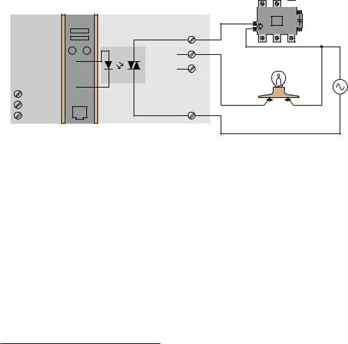
Indicator lamps, solenoid valves, and motor starters (assemblies consisting of contactors and overload protection devices) are all examples of discrete control devices. In a manner similar to discrete inputs, a PLC connects to any number of di erent discrete final control devices through a discrete output channel 2. Discrete output modules typically use the same form of opto-isolation to allow the PLC’s computer circuitry to send electrical power to loads: the internal PLC circuitry driving an LED which then activates some form of photosensitive switching device. Alternatively, small electromechanical relays may be used in lieu of opto-isolating semiconductor switching elements such as transistors (DC) or TRIACs (AC):
|
|
PLC |
Power |
Processor |
Discrete output card (TRIAC) |
|
||
supply |
|
Ch1 |
|
|
|
|
|
Optocoupler |
|
|
... Ch2 |
|
|
... Ch3 |
L1 |
|
|
L2/N |
|
|
Gnd |
|
VAC |
|
|


 Contactor
Lamp |
AC power |
|
supply |
Setting a bit (1) in the PLC’s output register sends a "high" signal to the LED inside the optocoupler, turning on the photo-TRIAC, sending AC power to the output channel to energize the load.
As with the schematic diagram for a discrete input module shown previously, the schematic diagram shown here for a discrete output module reveals the componentry typical for a single channel on that card. Each output channel has its own optocoupler, driven by its own unique memory register bit inside the PLC’s memory. Discrete output cards for PLCs also typically have 4, 8, 16, or 32 channels.
An important concept to master when working with DC discrete I/O is the distinction between current-sourcing and current-sinking devices. The terms “sourcing” and “sinking” refer to the direction of current (as denoted by conventional flow notation) into or out of a device’s control wire3. A device sending (conventional flow) current out of its control terminal to some other device(s) is said to be sourcing current, while a device accepting (conventional flow) current into its control terminal is said to be sinking current.
2I/O “channels” are often referred to as “points” in industry lingo. Thus, a “32-point input card” refers to an input circuit with 32 separate channels through which to receive signals from on/o switches and sensors.
3By “control wire,” I mean the single conductor connecting the I/O card channel to the field device, as opposed to conductors directly common with either the positive or negative lead of the voltage source. If you focus your attention on this one wire, noting the direction of conventional-flow current through it, the task of determining whether a device is sourcing or sinking current becomes much simpler.
12.2. INPUT/OUTPUT (I/O) CAPABILITIES |
781 |
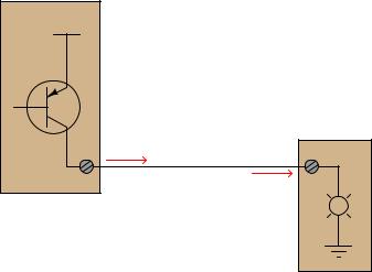
To illustrate, the following illustration shows a PLC output channel is sourcing current to an indicator lamp, which is sinking current to ground:
PLC discrete output channel
+V
Indicator lamp
Sourcing current
Sinking current
This is a "sourcing" or "PNP" discrete output channel
These terms really only make sense when electric current is viewed from the perspective of conventional flow, where the positive terminal of the DC power supply is envisioned to be the “source” of the current, with current finding its way “down” to ground (the negative terminal of the DC power supply). In every circuit formed by the output channel of a PLC driving a discrete control device, or by a discrete sensing device driving an input channel on a PLC, one element in the circuit must be sourcing current while the other is sinking current.
An engineering colleague of mine has a charming way to describe sourcing and sinking: blowing and sucking. A device that sources current to another “blows” current toward the other device. A device that sinks current “sucks” current from the other device. Many students seem to find these terms helpful in first mastering the distinction between sourcing and sinking despite (or perhaps because of!) their informal nature.
782 |
CHAPTER 12. PROGRAMMABLE LOGIC CONTROLLERS |
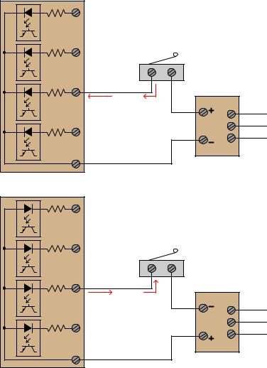
If the discrete device connecting to the PLC is not polarity-sensitive, either type of PLC I/O module will su ce. For example, the following diagrams show a mechanical limit switch connecting to a sinking PLC input and to a sourcing PLC input:
|
PLC discrete |
|
|
Ch 0 |
input card |
|
|
(sinking) |
|
||
|
|
||
|
|
Limit switch |
|
Ch 1 |
|
|
|
|
|
|
DC power |
|
|
|
supply |
Ch 2 |
Sinking |
Sourcing |
AC power |
|
current |
current |
L1 |
|
|
|
|
|
|
|
L2 |
Ch 3 |
|
|
Gnd |
|
|
|
|
Com |
|
|
|
|
PLC discrete |
|
|
Ch 0 |
input card |
|
|
(sourcing) |
|
||
|
|
||
Limit switch
Ch 1
|
|
|
DC power |
|
|
|
supply |
Ch 2 |
Sourcing |
Sinking |
AC power |
|
current |
current |
L1 |
|
|
|
|
|
|
|
L2 |
Ch 3 |
|
|
Gnd |
|
|
|
|
VDC |
|
|
|
Note the di erences in polarity and labeling between the sinking card’s common terminal and the sourcing card’s common terminal. On the “sinking” card, the input channel terminal is positive while the common (“Com”) terminal is negative. On the “sourcing” card, the input channel terminal is negative while the common (“VDC”) terminal is positive.
12.2. INPUT/OUTPUT (I/O) CAPABILITIES |
783 |
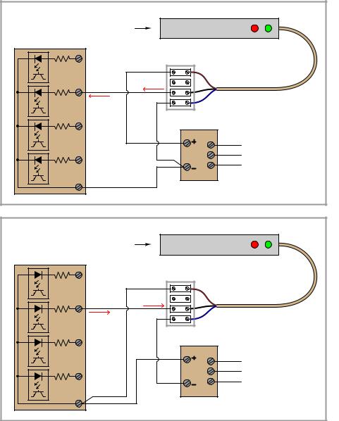
Some discrete sensing devices are polarity-sensitive, such as electronic proximity sensors containing transistor outputs. A “sourcing” proximity switch can only interface with a “sinking” PLC input channel, and vice-versa:
|
Switch actuates |
Current-sourcing (PNP) proximity switch |
||
PLC discrete |
|
|
||
|
when object |
|
|
|
input card |
|
|
|
|
|
approaches this |
|
|
|
(sinking) |
|
|
|
|
|
end |
|
|
|
|
|
|
|
|
|
Ch 0 |
|
|
+V |
|
|
|
Sourcing |
|
|
|
|
current |
Out |
|
|
|
|
|
|
Ch 1 |
Sinking |
|
Gnd |
|
|
current |
|
|
|
Ch 2 |
|
|
AC power |
|
|
|
|
L1 |
|
|
|
|
L2 |
|
Ch 3 |
|
|
Gnd |
|
|
|
|
|
|
Com |
|
|
|
|
Switch actuates |
Current-sinking (NPN) proximity switch |
||
PLC discrete |
|
|
||
|
when object |
|
|
|
input card |
|
|
|
|
|
approaches this |
|
|
|
(sourcing) |
|
|
|
|
|
end |
|
|
|
|
|
|
|
|
|
Ch 0 |
|
|
+V |
|
|
|
Sinking |
|
|
|
|
current |
Out |
|
|
|
|
|
|
Ch 1 |
Sourcing |
|
Gnd |
|
|
current |
|
|
|
Ch 2 |
|
|
AC power |
|
|
|
|
L1 |
|
|
|
|
L2 |
|
Ch 3 |
|
|
Gnd |
|
|
|
|
|
|
VDC |
|
|
|
In all cases, the “sourcing” device sends current out of its signal terminal while the “sinking” device takes current into its signal terminal.
784 |
CHAPTER 12. PROGRAMMABLE LOGIC CONTROLLERS |
Two photographs of a DC (sinking) discrete input module for an Allen-Bradley model SLC 500 PLC are shown here: one with the plastic cover closed over the connection terminals, and the other with the plastic cover opened up for viewing the terminals. A legend on the inside of the cover shows the purpose of each screw terminal: eight input channels (numbered 0 through 7) and two redundant “DC Com” terminals for the negative pole of the DC power supply to connect:
A standard feature found on practically every PLC discrete I/O module is a set of LED indicators visually indicating the status of each bit (discrete channel). On the SLC 500 module, the LEDs appear as a cluster of eight numbered squares near the top of the module.
A photograph of discrete output terminals on another brand of PLC (a Koyo model DL06) shows somewhat di erent labeling:
12.2. INPUT/OUTPUT (I/O) CAPABILITIES |
785 |
Here, each output channel terminal is designated with a letter/number code beginning with the letter “Y”. Several “common” terminals labeled with “C” codes service clusters of output channels. In this particular case, each “common” terminal is common only to four output channels. With sixteen total output channels on this PLC, this means there are four di erent “common” terminals. While this may seem somewhat strange (why not just have one “common” terminal for all sixteen output channels?), it more readily permits di erent DC power supplies to service di erent sets of output channels.
Electrical polarity is not an issue with AC discrete I/O, since the polarity of AC reverses periodically anyway. However, there is still the matter of whether the “common” terminal on a discrete PLC module will connect to the neutral (grounded) or hot (ungrounded) AC power conductor.
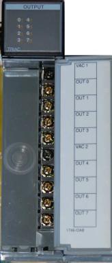
The next photograph shows a discrete AC output module for an Allen-Bradley SLC 500 PLC, using TRIACs as power switching devices rather than transistors as is customary with DC discrete output modules:
This particular eight-channel module provides two sets of TRIACs for switching power to AC loads, each set of four TRIACs receiving AC power from a “hot” terminal (VAC 1 or VAC 2), the other side of the load device being connected to the “neutral” (grounded) conductor of the AC power source.