


FuelEfficiencyFactormin will be calculated using CO2YOUR equivalent to 60.06 kg CO2/100km and
TYOURS set to 1.45 times the corrected average laptime of the fastest team that completes the endurance course.
X (power of the Time ratio) is to be defined.
APPENDIX T-1 STRUCTURAL EQUIVALENCY SPREADSHEET
Appendix T-1 is posted at www.fsaeonline.com.
APPENDIX T-2 IMPACT ATTENUATOR DATA REPORT
Appendix T-2 is posted at www.fsaeonline.com.
|
68 |
© 2013 SAE International. All Rights Reserved |
2014 Formula SAE® Rules |

PART AF - ALTERNATIVE FRAME RULES
ARTICLE 1: GENERAL REQUIREMENTS
These alternative structural requirements are intended to provide teams an alternative approach to the existing rules. The goal of these alternative rules is to provide a simpler alternative for monocoque designs and provide expanded design freedom for space frames and monocoques alike. The intent is not to alter allowable structures but to change the requirement process for showing compliance with the rules.
Note: Generally SI units are used in these alternative frame rules with some dual references.
AF1.1 Unless listed below under section AF7 “Non-Applicable Rules” all requirements of the rest of the rules apply in these alternative requirements.
AF1.2 The AF Rules are considered a work in progress. As such, the Rules Committee and reviewers of the SRCF (below) may, at any time, amend and clarify these rules to maintain the spirit in which they were written and close any unintended loop holes.
AF1.3 These rules are recommended for existing teams who have experience designing, constructing and competition with vehicles in the past. There is no experience requirement.
AF1.4 Notice of Intent - Teams planning to build a vehicle to this alternative rule set for entry into a North American competition must notify the Rules Committee of their intent by the date specified in the action deadlines for the competition. Include a short paragraph detailing your team’s finite element capability and showing you can meet all analytical requirements specified in this Appendix. Your “Notice of Intent” should include the email addresses and phones numbers of the team members who can answer any questions the Committee may have about your proposal.
The notice of intent submission should also include a brief report analyzing the sample structures problem posted to the SAE website. Please include a brief text description of your analysis approach, what software you used, the element types, mesh quality and boundary conditions that were used in this analysis. The results provided will be used to assess the team’s capability to perform this type of structural analysis.
AF1.5 The Rules Committee will remain in contact with teams using the AF rules to help them develop and document their frames and to give the Committee data and feedback that can be used to refine the AF rules.
AF1.6 Notice of Intent – Procedure
A.Address – Teams using the AF Rules for a North America competition must submit their “Notice of Intent” to the FSAE Rules committee at:fase@sae.org.
B.Due Date – “Notices of Intent” to use the AF Rules the notice of intent must submitted to the Rules Committee by the date posted on the SAE Website.
C.Acknowledgement – The Rules Committee will review your “Notice of Intent” and will try to respond with their approval/disapproval within 15 days.
ARTICLE 2: STRUCTURAL REQUIREMENTS CERTIFICATION FORM (SRCF)
Since there is no baseline steel design in this alternative rule set, the team must show they are meeting the functional structural requirements.
|
69 |
© 2013 SAE International. All Rights Reserved |
2014 Formula SAE® Rules |
When the Alternate Frame Rules are used the Structural Requirements Certification Form (SRCF) supersedes the Structural Equivalency Spreadsheet (SES) which does not have to be submitted.
AF2.1 SRCF - Submission Process
A.Address – SRCFs must be submitted to the officials at the competition you are entering at the address indicated on the competition website or shown in the Appendix.
B.Due Date and Late Submission Penalty – SRCFs must be submitted no later than the due date specified on the competition website (For US events reference “Action Deadlines”). Teams that submit their SRCF after the relevant due date will be penalized ten (10) points per day up to a maximum of fifty (50) points which will be deducted from the team’s total score.
C.Acknowledgement – North American Competitions – SRCFs submitted for vehicles entered into competitions held in North America will be acknowledged upon receipt.
ARTICLE 3: DEFINITIONS
The following additional definitions apply throughout the Rules document in addition to the ones listed in T3.3
•Failure - Tensile, compressive, shear load or buckling critical load lower than the specified load. All failure modes have to be considered for every load case.
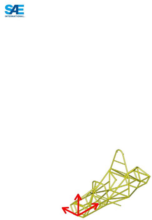
•Directions – The following coordinate system and labeling convention is used within these rules
o Longitudinal (X) o Transverse (Y) o Vertical (Z)
Z
Y
X
ARTICLE 4: STRUCTURAL REQUIREMENTS
AF4.1 Main Roll Hoop, Bracing and Bracing Supports
AF4.1.1 Load Applied: Fx = 6.0 kN, Fy=5.0 kN, Fz=-9.0 kN
AF4.1.2 Application point: Top of Main Roll Hoop
AF4.1.3 Boundary Condition: Fixed displacement (x,y,z) but not rotation of the bottom nodes of both sides of the front and main roll hoops.
AF4.1.4 Max Allowable Deflection: 25mm
|
70 |
© 2013 SAE International. All Rights Reserved |
2014 Formula SAE® Rules |
AF4.1.5 Failure must not occur anywhere in structure
AF4.2 Front Roll Hoop
AF4.2.1 Load Applied: Fx = 6.0 kN, Fy=5.0 kN, Fz=-9.0 kN
AF4.2.2 Application point: Top of Front Roll Hoop
AF4.2.3 Boundary Condition: Fixed displacement (x,y,z) but not rotation of the bottom nodes of both sides of the front and main roll hoops.
AF4.2.4 Max Allowable Deflection: 25mm
AF4.2.5 Failure must not occur anywhere in structure
AF4.3 Side Impact
AF4.3.1 Load Applied: Fx = 0 kN, Fy=7 kN, Fz 0 kN. Vector direction of lateral load to be in toward the driver.
AF4.3.2 Application point: All structural locations between front roll hoop and main roll hoop in the side impact zone defined in T3.3. The analysis may show worst case only but need to support choice of location to justify why it is worst.
AF4.3.3 Boundary Condition: Fixed displacement (x,y,z) but not rotation of the bottom nodes of both sides of the front and main roll hoops.
AF4.3.4 Max Allowable Deflection: 25 mm
AF4.3.5 Failure must not occur anywhere in structure
AF4.4 Front Bulkhead & Bulkhead Support
AF4.4.1 Load Applied: Fx = 150 kN, Fy=0 kN, Fz 0 kN.
AF4.4.2 Application point: use the actual attachment points between the impact attenuator and the front bulkhead
AF4.4.3 Boundary Condition: Fixed displacement (x,y,z) but not rotation of the bottom nodes of both sides of the main roll hoop and both locations where the main hoop and shoulder harness tube connect. Monocoques should use both sides of the bottom of the main hoop and both sides of the upper attachment point between the main hoop and monocoque.
AF4.4.4 Max Allowable Deflection: 25mm
AF4.4.5 Failure must not occur anywhere in structure
AF4.5 Shoulder Harness Attachment
AF4.5.1 Load Applied: 13.2 kN at seat belt attachment angle per attachment point.
AF4.5.2 Application point: Both harness attachment points simultaneously
|
71 |
© 2013 SAE International. All Rights Reserved |
2014 Formula SAE® Rules |

AF4.5.3 Boundary Condition: Fixed displacement (x,y,z) but not rotation of the bottom nodes of both sides of the front and main roll hoops.
AF4.5.4 Max Allowable Deflection: 25mm
AF4.5.5 Failure must not occur anywhere in structure
AF4.6 Lap & Anti-Submarine AF Harness Attachment
AF4.6.1 Load Applied: The loads specified in the monocoque harness attachment rules should be used on each AF attachment point.
AF4.6.2 Application point: All harness attachment points simultaneously (same load case)
AF4.6.3 Boundary Condition: Fixed displacement (x,y,z) but not rotation of the bottom nodes of both sides of the front and main roll hoops.
AF4.6.4 Max Allowable Deflection: 25mm
AF4.6.5 Failure must not occur anywhere in structure
AF4.7 Front Bulkhead & Bulkhead Support Off Axis
AF4.7.1 Load Applied: Fx = 149 kN, Fy=17.25 kN, Fz 0 kN.
AF4.7.2 Application point: Create load application node in the front bulkhead plane at the center of the front bulkhead. Load application node may be rigidly connected to the front bulkhead and impact attenuator attachment points.
AF4.7.3 Boundary Condition: Fixed displacement (x,y,z) but not rotation of the bottom nodes of both sides of the main roll hoop and both locations where the main hoop and shoulder harness tube connect. Monocoques should use both sides of the bottom of the main hoop and both sides of the upper attachment point between the main hoop and monocoque.
AF4.7.4 Max Allowable Deflection: 25mm
AF4.7.5 Failure must not occur anywhere in structure
ARTICLE 5: GENERAL ANALYSIS REQUIREMENTS
The following requirements apply to the submitted structural certification process.
AF5.1 Good analysis practice must be used and all assumptions and modeling approximations are subject to approval during the SRC process. This includes but is not limited to mechanical properties, mesh size and mesh quality.
AF5.2 A Nastran analysis deck must be submitted electronically with the SRCF and supporting documentation. Nastran does not have to be used for the analysis, but is the required format for the organizer's to review the analysis input decks.
AF5.3 Tubes with wall thickness less than 1.25 mm (0.049 inches) cannot be included in the analysis
AF5.4 Holes in tubes may be neglected from the overall frame/monocoque model global results. However for each load case, the force and moments at both sides of the tubes need to be applied to a shell or
|
72 |
© 2013 SAE International. All Rights Reserved |
2014 Formula SAE® Rules |
solid model of the tube with the hole or cutout geometry modeled. The tube around the holes and cutouts may not show failure.
AF5.5 Offsets between tubes at nodes need a detailed analysis similar to 5.3 where the actual connection is modeled using the end constraints from the overall vehicle model. Shell or solid models must be used.
AF5.6 The following alternative boundary condition is acceptable for all structural requirements. The alternative is to not include the nodal constraints and instead run the model with inertia relief. In this case the mass distribution of the vehicle must closely approximate the actual intended mass distribution. Evidence must be provided supporting the mass distribution used in the model. A driver mass of 77 kg and a minimum vehicle mass of 300 kg must be used, even if these differ from the team's predicted vehicle mass.
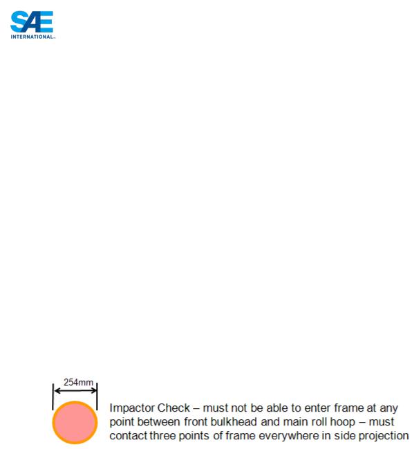
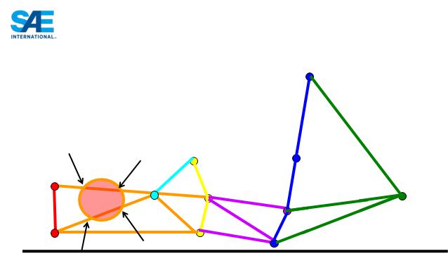
ARTICLE 6: INTRUSION PREVENTION
Since the exact configuration of the tubes is not specified this rule is intended to limit the size of object which can intrude into the driver’s cell.
AF6.1 An impactor is defined as a circular disk with diameter of 254 mm (10 inches). The thickness is not relevant, but will generally be around 2mm (0.080 inches) for the inspection process.
AF6.2 The primary structure between the front bulkhead and main roll hoop must not allow the impactor to enter the primary structure.
AF6.3 Anywhere on the structure where the impactor is attempted to be passed through the impactor must contact the structure in at least three points. This is not a projection requirement but a full 3- dimensional requirement.
|
73 |
© 2013 SAE International. All Rights Reserved |
2014 Formula SAE® Rules |
AF6.4 The impactor is a 3-dimensional requirement. It applies to all faces of the structure, including the front, sides, top, floor and rear, excluding only the cockpit opening specified in T4.1.1. If the driver is seated fully in front of the main hoop then the requirement does not apply behind the main hoop. If the driver is seated partially or fully behind the main hoop then the requirement extends to the end of the main hoop braces.
ARTICLE 7: NON-APPLICABLE RULES
The following rules are not applicable when building a frame to this alternative rule set.
AF7.1 T3.11.4 In the side view of the vehicle, the portion of the Main Roll Hoop that lies above its attachment point to the Major Structure of the Frame must be within ten degrees (10°) of the vertical.
AF7.2 T3.12.6 In side view, no part of the Front Hoop can be inclined at more than twenty degrees (20°) from the vertical.
AF7.3 T3.13.3 In the side view of the Frame, the Main Hoop and the Main Hoop braces must not lie on the same side of the vertical line through the top of the Main Hoop, i.e. if the Main Hoop leans forward, the braces must be forward of the Main Hoop, and if the Main Hoop leans rearward, the braces must be rearward of the Main Hoop.
AF7.4 T3.13.4 The Main Hoop braces must be attached as near as possible to the top of the Main Hoop but not more than 160 mm (6.3 in) below the top-most surface of the Main Hoop. The included angle formed by the Main Hoop and the Main Hoop braces must be at least thirty degrees (30°).
AF7.5 T3.13.6 The attachment of the Main Hoop braces must be capable of transmitting all loads from the Main Hoop into the Major Structure of the Frame without failing. From the lower end of the braces there must be a properly triangulated structure back to the lowest part of the Main Hoop and the node at which the upper side impact tube meets the Main Hoop. This structure must meet the minimum requirements for Main Hoop Bracing Supports (see Rule T3.4) or an SES approved alternative. Bracing loads must not be fed solely into the engine, transmission or differential, or through suspension components.
|
74 |
© 2013 SAE International. All Rights Reserved |
2014 Formula SAE® Rules |

AF7.6 T3.14.4 The Front Hoop braces must be attached as near as possible to the top of the Front Hoop but not more than 50.8 mm (2 in) below the top-most surface of the Front Hoop. See Figure 3.
AF7.7 T3.14.5 If the Front Hoop leans rearwards by more than ten degrees (10°) from the vertical, it must be supported by additional bracing to the rear. This bracing must be constructed of material per Rule T3.4.1.
AF7.8 T3.20.1 The Front Bulkhead must be securely integrated into the Frame.
AF7.9 T3.20.2 The Front Bulkhead must be supported back to the Front Roll Hoop by a minimum of three
(3) Frame Members on each side of the vehicle with one at the top (within 50.8 mm (2 inches) of its top-most surface), one (1) at the bottom, and one (1) as a diagonal brace to provide triangulation.
AF7.10 T3.20.3 The triangulation must be node-to-node, with triangles being formed by the Front Bulkhead, the diagonal and one of the other two required Front Bulkhead Support Frame Members.
AF7.11 T3.25.4 With proper gusseting and/or triangulation, it is permissible to fabricate the Side Impact Structural members from more than one piece of tubing.
|
75 |
© 2013 SAE International. All Rights Reserved |
2014 Formula SAE® Rules |

2014 FORMULA SAE RULES
PART IC - INTERNAL COMBUSTION ENGINE VEHICLES
ARTICLE 1: INTERNAL COMBUSTION ENGINE POWERTRAINS
IC1.1 Engine Limitation
IC1.1.1 The engine(s) used to power the car must be a piston engine(s) using a four-stroke primary heat cycle with a displacement not exceeding 610 cc per cycle. Hybrid powertrains, such as those using electric motors running off stored energy, are prohibited.
Note: All waste/rejected heat from the primary heat cycle may be used. The method of conversion is not limited to the four-stroke cycle.
IC1.1.2 The engine can be modified within the restrictions of the rules.
IC1.1.3 If more than one engine is used, the total displacement cannot exceed 610 cc and the air for all engines must pass through a single air intake restrictor (see IC1.6 “Intake System Restrictor.”)
IC1.2 Engine Inspection
The organizer will measure or tear down a substantial number of engines to confirm conformance to the rules. The initial measurement will be made externally with a measurement accuracy of one (1) percent. When installed to and coaxially with spark plug hole, the measurement tool has dimensions of 381 mm (15 inches) long and 30 mm (1.2 inches) diameter. Teams may choose to design in access space for this tool above each spark plug hole to reduce time should their vehicle be inspected.
IC1.3 Starter
Each car must be equipped with an on-board starter which, during the competition, must be used to start the car at all times. Push starts, or the use of a remote starter, are prohibited.
IC1.4 Air Intake System
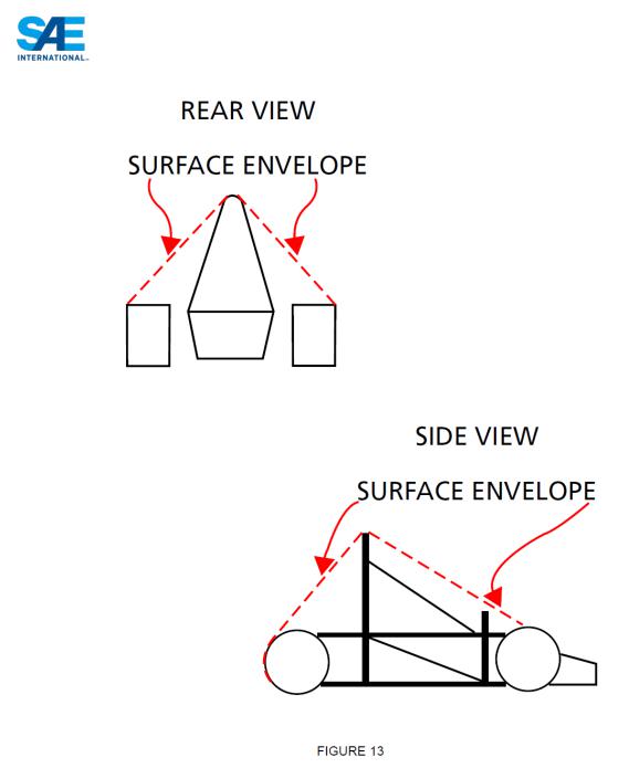
IC1.4.1 Air Intake System Location
All parts of the engine air and fuel control systems (including the throttle or carburetor, and the complete air intake system, including the air cleaner and any air boxes) must lie within the surface defined by the top of the roll bar and the outside edge of the four tires. (See Figure 13).
|
76 |
© 2013 SAE International. All Rights Reserved |
2014 Formula SAE Rules |
IC1.4.2 |
Any portion of the air intake system that is less than 350 mm (13.8 inches) above the ground must be |
|
|
shielded from side or rear impact collisions by structure built to Rule T3.25 or T3.34 as applicable. |
|
IC1.4.3 |
Intake Manifold – The intake manifold must be securely attached to the engine block or cylinder head |
|
|
with brackets and mechanical fasteners. This precludes the use of hose clamps, plastic ties, or safety |
|
|
wires. The use of rubber bushings or hose is acceptable for creating and sealing air passages, but is not |
|
|
considered a structural attachment. |
|
IC1.4.4 |
Intake systems with significant mass or cantilever from the cylinder head must be supported to |
|
|
prevent stress to the intake system. Supports to the engine must be rigid. Supports to the frame or |
|
|
chassis must incorporate some isolation to allow for engine movement and chassis flex. |
|
IC1.5 |
Throttle and Throttle Actuation |
|
IC1.5.1 |
Carburetor/Throttle Body |
|
|
|
77 |
© 2013 SAE International. All Rights Reserved |
2014 Formula SAE Rules |
|

The car must be equipped with a carburetor or throttle body. The carburetor or throttle body may be of any size or design.
IC1.5.2 Throttle Actuation
The throttle must be actuated mechanically, i.e. via a cable or a rod system. The use of electronic throttle control (ETC) or “throttle-by-wire” is prohibited.
IC1.5.3 The throttle cable or rod must have smooth operation, and must not have the possibility of binding or sticking.
IC1.5.4 The throttle actuation system must use at least two (2) return springs located at the throttle body, so that the failure of any component of the throttle system will not prevent the throttle returning to the closed position.
Note: Throttle Position Sensors (TPS) are NOT acceptable as return springs.
IC1.5.5 Throttle cables must be at least 50.8 mm (2 inches) from any exhaust system component and out of the exhaust stream.
IC1.5.6 A positive pedal stop must be incorporated on the throttle pedal to prevent over stressing the throttle cable or actuation system.
IC1.5.7 The throttle pedal cable must be protected from being bent or kinked by the driver’s foot when it is operated by the driver or when the driver enters or exits the vehicle.
IC1.5.8 If the throttle system contains any mechanism that could become jammed, for example a gear mechanism, then this must be covered to prevent ingress of any debris.
IC1.6 Intake System Restrictor
IC1.6.1 In order to limit the power capability from the engine, a single circular restrictor must be placed in the intake system between the throttle and the engine and all engine airflow must pass through the restrictor.
IC1.6.2 Any device that has the ability to throttle the engine downstream of the restrictor is prohibited.
IC1.6.3 The maximum restrictor diameters which must be respected at all times during the competition are:
-Gasoline fueled cars - 20.0 mm (0.7874 inch)
-E-85 fueled cars – 19.0 mm (0.7480 inch)
IC1.6.4 The restrictor must be located to facilitate measurement during the inspection process.
IC1.6.5 The circular restricting cross section may NOT be movable or flexible in any way, e.g. the restrictor may not be part of the movable portion of a barrel throttle body.
IC1.6.6 If more than one engine is used, the intake air for all engines must pass through the one restrictor.
IC1.7 Turbochargers & Superchargers
IC1.7.1 Turbochargers or superchargers are allowed if the competition team designs the application. Engines that have been designed for and originally come equipped with a turbocharger are not allowed to compete with the turbo installed.
|
78 |
© 2013 SAE International. All Rights Reserved |
2014 Formula SAE Rules |

IC1.7.2 The restrictor must be placed upstream of the compressor but after the carburetor or throttle valve. Thus, the only sequence allowed is throttle, restrictor, compressor, engine.
IC1.7.3 The intake air may be cooled with an intercooler (a charge air cooler). Only ambient air may be used to remove heat from the intercooler system. Air-to-air and water-to air intercoolers are permitted. The coolant of a water-to-air intercooler system must comply with Rule T8.1.
IC1.8 Fuel Lines
IC1.8.1 Plastic fuel lines between the fuel tank and the engine (supply and return) are prohibited.
IC1.8.2 If rubber fuel line or hose is used, the components over which the hose is clamped must have annular bulb or barbed fittings to retain the hose. Also, clamps specifically designed for fuel lines must be used. These clamps have three (3) important features, (i) a full 360 degree (360°) wrap, (ii) a nut and bolt system for tightening, and (iii) rolled edges to prevent the clamp cutting into the hose. Worm-gear type hose clamps are not approved for use on any fuel line.
IC1.8.3 Fuel lines must be securely attached to the vehicle and/or engine.
IC1.8.4 All fuel lines must be shielded from possible rotating equipment failure or collision damage.
IC1.9 Fuel Injection System Requirements
The following requirements apply to fuel injection systems.
IC1.9.1 Low Pressure Injection (LPI)
Low pressure fuel injection systems are those functioning at a pressure below 10 Bar (145 psi). Most Port Fuel Injected (PFI) fuel systems are low pressure.
(A)Fuel Lines – On low pressure fuel injected systems, any flexible fuel lines must be either (i) metal braided hose with either crimped-on or reusable, threaded fittings, or (ii) reinforced rubber hose with some form of abrasion resistant protection with fuel line clamps per B8.8.2 . Note: Hose clamps over metal braided hose will not be accepted.
(B)Fuel Rail – The fuel rail must be securely attached to the engine cylinder block, cylinder head, or intake manifold with mechanical fasteners. This precludes the use of hose clamps, plastic ties, or safety wire.
(C)Intake Manifold – On engines with port fuel injection, the intake manifold must be securely attached to the engine block or cylinder head.
IC1.9.2 High Pressure Injection (HPI) / Direct Injection (DI)
High pressure fuel systems are those functioning at 10 Bar (145 psi) pressure or above. Direct injection fuel systems are those where the injection occurs directly into the combustion system. DI systems often utilize a low pressure electric fuel pump and high pressure mechanical “boost” pump driven off the engine. The high pressure lines are those between the boost pump and injectors, and the low pressure lines lead from the electric supply pump up to the boost pump.
|
79 |
© 2013 SAE International. All Rights Reserved |
2014 Formula SAE Rules |

Pressure Relief
Valve
High Pressure
Pump
Low Pressure Pump
(A)High Pressure Fuel Lines – All high pressure fuel lines, normally those downstream of the high pressure pump on Direct Injection systems, must be stainless steel rigid line or Aeroquip FC807 smooth bore PTFE hose with stainless steel reinforcement and visible Nomex tracer yarn. Equivalent products may be used with prior Rules Committee approval. Use of elastomeric seals is prohibited. Lines must be rigidly connected every 100mm by mechanical fasteners to structural engine components such as cylinder heads or block.
(B)Low Pressure Fuel Lines – Low pressure lines, normally those upstream of the high pressure pump, that are flexible must be either (i) metal braided hose with either crimped-on or reusable, threaded fittings, or (ii) reinforced rubber hose with some form of abrasion resistant protection with fuel line clamps per B8.8.2. Note: Hose clamps over metal braided hose will not be accepted.
(C)Fuel Rail – The fuel rail must be securely attached to the engine cylinder head with mechanical fasteners. This precludes the use of hose clamps, plastic ties, or safety wire. The fastening method must be sufficient to hold the fuel rail in place with the maximum regulated pressure acting on the injector internals and neglecting any assistance from in-cylinder pressure acting on the injector tip.
(D)High Pressure Fuel Pump – The fuel pump must be rigidly mounted to structural engine components such as the cylinder head or engine block.
(E)Pressure Regulator – A fuel pressure regulator must be fitted between the high and low pressure sides of the fuel system in parallel with the DI boost pump. The external regulator must be used even if the DI boost pump comes equipped with an internal regulator.
(F)Required Test – Prior to the tilt test specified in B9.9, engines fitted with mechanically actuated fuel pumps must be run to fill and pressure the system downstream of the high pressure pump.
IC1.10 Crankcase / engine lubrication venting
IC1.10.1 Any crankcase or engine lubrication vent lines routed to the intake system must be connected upstream of the intake system restrictor.
IC1.10.2 Crankcase breathers that pass through the oil catch tank(s) to exhaust systems, or vacuum devices that connect directly to the exhaust system, are prohibited.
|
80 |
© 2013 SAE International. All Rights Reserved |
2014 Formula SAE Rules |
ARTICLE 2: FUEL AND FUEL SYSTEM
IC2.1 Fuel
The basic fuel available at competitions in the Formula SAE Series is unleaded gasoline. For the FSAE North American competitions this should have an octane rating of 91 (R+M)/2 (approximately 95 RON) minimum and for other competitions, the unleaded gasoline that will be available will be published by the relevant organizing committee. However, the basic fuel may be changed at the discretion of the organizing body. Other fuels may be available at the discretion of the organizing body.
IC2.1.1 Unless otherwise announced by the individual organizing body, the fuel at competitions in the Formula SAE Series will be provided by the organizer.
IC2.1.2 During all performance events the cars must be operated with the fuels provided by the organizer at the competition.
IC2.1.3 Nothing may be added to the provided fuels. This prohibition includes nitrous oxide or any other oxidizing agent.
Note 1: Teams are advised that the fuel supplied in the United States is subject to various federal and state regulations and may contain up to ten percent (10%) ethanol. The exact chemical composition and physical characteristics of the available fuel may not be known prior to the competition.
Note 2: The fuels provided at Formula SAE Michigan are expected to be 93 and 100 octane [(R+M)/2] gasoline and E-85. The fuels that will be provided at Formula SAE Lincoln have not been finalized. We anticipate providing 2 grades of gasoline, one either 91 or 93 octane and the second either 97 or 100 octane [(R+M/2]. We will also provide E-85. Teams competing at FSAE Lincoln should watch the FSAE news page for announcements. Fuel types are subject to change.
Note 3: The fuels provided at FSAE competitions depend on the grades the suppliers have available. Although the organizers make every effort to provide the announced fuels, events beyond our control may require substitutions. We strongly advise teams to monitor the competition websites for updated information on fuel types.
Consult the individual competition websites for fuel types and other information.
IC2.2 Fuel Additives - Prohibited
IC2.2.1 No agents other than fuel (gasoline or E85), and air may be induced into the combustion chamber. Non-adherence to this rule will be reason for disqualification.
IC2.2.2 Officials have the right to inspect the oil.
IC2.3 Fuel Temperature Changes - Prohibited
The temperature of fuel introduced into the fuel system may not be changed with the intent to improve calculated efficiency.
IC2.4 Fuel Tanks
IC2.4.1 The fuel tank is defined as that part of the fuel containment device that is in contact with the fuel. It may be made of a rigid material or a flexible material.
|
81 |
© 2013 SAE International. All Rights Reserved |
2014 Formula SAE Rules |

IC2.4.2 Fuel tanks made of a rigid material cannot be used to carry structural loads, e.g. from roll hoops, suspension, engine or gearbox mounts, and must be securely attached to the vehicle structure with mountings that allow some flexibility such that chassis flex cannot unintentionally load the fuel tank.
IC2.4.3 Any fuel tank that is made from a flexible material, for example a bladder fuel cell or a bag tank, must be enclosed within a rigid fuel tank container which is securely attached to the vehicle structure. Fuel tank containers (containing a bladder fuel cell or bag tank) may be load carrying.
IC2.4.4 Any size fuel tank may be used.
IC2.4.5 The fuel system must have a provision for emptying the fuel tank if required.
IC2.5 Fuel System Location Requirements
IC2.5.1 All parts of the fuel storage and supply system must lie within the surface defined by the top of the roll bar and the outside edge of the four tires. (See Figure 13).
IC2.5.2 All fuel tanks must be shielded from side or rear impact collisions. Any fuel tank which is located outside the Side Impact Structure required by T3.25 or T3.34 must be shielded by structure built to T3.3, or T3.34.
IC2.5.3 A firewall must be incorporated to separate the fuel tank from the driver, per Rule T4.5.
IC2.6 Fuel Tank Filler Neck & Sight Tube
IC2.6.1 All fuel tanks must have a filler neck:
(a)at least 38 mm (1.5 inches) diameter,
(b)at least 125 mm (4.9 inches) vertical height and
(c)angled at no more than forty-five degrees (45°) from the vertical.
IC2.6.2 The 125 mm of vertical height must be above the top level of the tank, and must be accompanied by a clear fuel resistant sight tube for reading the fuel level. (Figure 14)
|
82 |
© 2013 SAE International. All Rights Reserved |
2014 Formula SAE Rules |
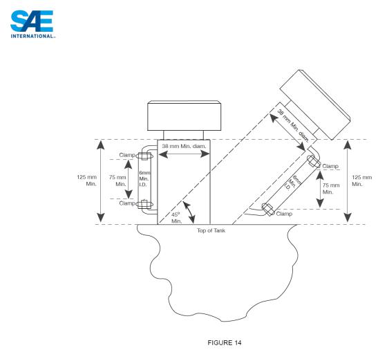
IC2.6.3 The sight tube must have at least 75 mm (3 inches) of vertical height and a minimum inside diameter of 6 mm (0.25 inches).
IC2.6.4 The sight tube must not run below the top surface of the fuel tank.
IC2.6.5 A clear filler tube may be used as a sight tube, subject to approval by the Rules Committee or technical inspectors at the event.
IC2.6.6 Fuel Level Line - A permanent, non-moveable fuel level line must be located between 12.7 mm and 25.4 mm (0.5 inch and 1 inch) below the top of the sight tube. This line will be used as the fill line for the Tilt Test (Rule T8.5), and before and after the Endurance Test to measure the amount of fuel used during the Endurance Event.
IC2.6.7 The sight tube and fuel level line must be clearly visible to an individual filling the tank.
IC2.7 Tank Filling Requirement
IC2.7.1 The fuel tank must be capable of being filled to capacity without manipulating the tank or the vehicle in any manner. During fueling or refueling the vehicle may only be touched by the fuel crew and officials. The tank will be filled to the fill line, or if a filing system is used, to the automatic stop point. If, for any reason, the fuel level changes after the team has moved the vehicle, then no additional fuel will be added.
IC2.7.2 The fuel system must be designed such that the spillage during refueling cannot contact the driver position, exhaust system, hot engine parts, or the ignition system.
|
83 |
© 2013 SAE International. All Rights Reserved |
2014 Formula SAE Rules |

IC2.7.3 Belly pans must be vented to prevent accumulation of fuel. At least 2 holes, each of a minimum diameter of 25 mm, must be provided in the lowest part of the structure in such a way as to prevent accumulation of volatile liquids and/or vapours.
IC2.8 Venting Systems
IC2.8.1 The fuel tank and carburetor venting systems must be designed such that fuel cannot spill during hard cornering or acceleration. This is a concern since motorcycle carburetors normally are not designed for lateral accelerations.
IC2.8.2 All fuel vent lines must be equipped with a check valve to prevent fuel leakage when the tank is inverted. All fuel vent lines must exit outside the bodywork.
ARTICLE 3: EXHAUST SYSTEM AND NOISE CONTROL
IC3.1 Exhaust System General
IC3.1.1 Exhaust Outlet
The exhaust must be routed so that the driver is not subjected to fumes at any speed considering the draft of the car.
IC3.1.2 The exhaust outlet(s) must not extend more than 45 cm (17.7 inches) behind the centerline of the rear axle, and shall be no more than 60 cm (23.6 inches) above the ground.
IC3.1.3 Any exhaust components (headers, mufflers, etc.) that protrude from the side of the body in front of the main roll hoop must be shielded to prevent contact by persons approaching the car or a driver exiting the car.
IC3.2 Noise Measuring Procedure
IC3.2.1 The sound level will be measured during a static test. Measurements will be made with a free-field microphone placed free from obstructions at the exhaust outlet level, 0.5 m (19.68 inches) from the end of the exhaust outlet, at an angle of forty-five degrees (45°) with the outlet in the horizontal plane. The test will be run with the gearbox in neutral at the engine speed defined below. Where more than one exhaust outlet is present, the test will be repeated for each exhaust and the highest reading will be used.
IC3.2.2 The car must be compliant at all engine speeds up to the test speed defined below.
IC3.2.3 If the exhaust has any form of movable tuning or throttling device or system, it must be compliant with the device or system in all positions. The position of the device must be visible to the officials for the noise test and must be manually operable by the officials during the noise test.
IC3.2.4 Test Speeds
The test speed for a given engine will be the engine speed that corresponds to an average piston speed of 914.4 m/min (3,000 ft/min) for automotive or motorcycle engines, and 731.5 m/min (2,400 ft/min) for “industrial engines”. The calculated speed will be rounded to the nearest 500 rpm. The test speeds for typical engines will be published by the organizers.
An “industrial engine” is defined as an engine which, according to the manufacturers’ specifications and without the required restrictor, is not capable of producing more than 5 hp per 100cc. To have an engine classified as “an industrial engine”, approval must be obtained from organizers prior to the Competition.
|
84 |
© 2013 SAE International. All Rights Reserved |
2014 Formula SAE Rules |

IC3.3 Maximum Sound Level
The maximum permitted sound level is 110 dBA, fast weighting.
IC3.4 Noise Level Re-testing
At the option of the officials, noise can be measured at any time during the competition. If a car fails the noise test, it will be withheld from the competition until it has been modified and re-passes the noise test.
ARTICLE 4: ELECTRICAL SYSTEM AND SHUTDOWN SYSTEM
IC4.1 Master Switches
IC4.1.1 The vehicle must be equipped with two (2) master switches which form part of the shutdown system. Actuating either switch must stop the engine.
IC4.1.2 The international electrical symbol consisting of a red spark on a white-edged blue triangle must be affixed in close proximity to each switch.
Note: Teams are reminded that any alternator field wire must also be disabled by each master switch to prevent any possible feedback through the field coil circuit.
IC4.2 Primary Master Switch
IC4.2.1 The primary master switch must:
a.Be located on the (driver’s) right side of the vehicle, in proximity to the Main Hoop, at shoulder height and be easily actuated from outside the car.
b.Disable power to ALL electrical circuits, including the battery, alternator, lights, fuel pump(s), ignition and electrical controls.
c.All battery current must flow through this switch.
d.Be of a rotary type and must be direct acting, i.e. it cannot act through a relay.
An example of a typical switch that meets these requirements is shown below.
IC4.2.2 The “OFF” position of the primary master switch must be clearly marked.
IC4.3 Cockpit-mounted Master Switch
IC4.3.1 The cockpit-mounted master switch:
a.Must be located to provide easy actuation by the driver in an emergency or panic situation.
b.Must be located within easy reach of the belted-in driver, alongside the steering wheel, and unobstructed by the steering wheel or any other part of the car. It is suggested that it be placed on the same side of the steering wheel as the shifter mechanism.
|
85 |
© 2013 SAE International. All Rights Reserved |
2014 Formula SAE Rules |
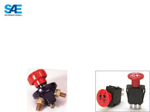
c.Must be a push/pull Emergency switch. The switch must be installed such that:
i.From the ON position, pushing on the switch will disable power to the ignition and all fuel pumps, and
ii.From the OFF position, pulling on the switch will enable power to the ignition and fuel pump(s). Switches that require a twist or twist and pull to enable power are acceptable.
d.May act through a relay.
Examples of typical switches that meet these requirements are shown below.
IC4.4 Batteries
IC4.4.1 All batteries, i.e. on-board power supplies, must be attached securely to the frame.
IC4.4.2 Any wet-cell battery located in the driver compartment must be enclosed in a nonconductive marinetype container or equivalent.
IC4.4.3 The hot (ungrounded) terminal must be insulated.
IC4.4.4 Battery packs based on Lithium Chemistry other than Lithium Iron Phosphate (LiFePO4):
a.must be commercially manufactured items
b.must have over voltage, under voltage, short circuit and over temperature cell protection
c.must be separated from the driver by a firewall
IC4.4.5 All batteries using chemistries other than lead acid must be presented at technical inspection with markings identifying it for comparison to a datasheet or other documentation proving the pack and supporting electronics meet all rules requirements
IC4.5 Brake-Over-Travel-Switch
The Brake-Over-Travel-Switch forms part of the shutdown system and as defined in T7.3 must kill the engine and fuel pumps.
|
86 |
© 2013 SAE International. All Rights Reserved |
2014 Formula SAE Rules |

2014 FORMULA SAE RULES
PART EV - TECHNICAL REGULATIONS – ELECTRIC VEHICLES
The principle of the newly introduced Electric Vehicle part is to allow the development of fully electric vehicles within the FSAE framework. These rules are based on the electric vehicle regulations developed by Formula Student and Formula Student Germany, and also include elements of the Formula Hybrid Rules.
ARTICLE 1: ELECTRIC SYSTEM DEFINITIONS
EV1.1 High-Voltage (HV) and Low-Voltage (LV)
EV1.1.1 Whenever a circuit has a potential difference where the nominal operation voltage is greater than 40V DC or 25V AC RMS it is defined as part of the High Voltage or tractive system.
EV1.1.2 The maximum permitted voltage that may occur between any two electrical connections is different between the competitions allowing electric vehicles. The following table lists the respective values:
Competition |
Voltage |
|
Level |
||
|
||
Formula SAE Electric |
300 VDC |
|
|
|
|
Formula SAE Brazil |
300 VDC |
|
|
|
|
Formula SAE Australasia |
600 VDC |
|
|
|
|
Formula SAE Italy |
600 VDC |
|
|
|
|
Formula Student |
600 VDC |
|
|
|
|
Formula Student |
600 VDC |
|
Germany |
||
|
||
Student Formula Japan |
Refer to SFJ |
|
website |
||
|
||
|
|
EV1.1.3 Low voltage is defined as any voltage below and including 40V DC or 25V AC RMS.
EV1.1.4 The tractive system accumulator is defined as all the battery cells or super-capacitors that store the electrical energy to be used by the tractive system.
EV1.1.5 Accumulator segments are sub-divisions of the accumulator and must respect either a maximum voltage or energy limit. Splitting the accumulator into its segments is intended to reduce the risks associated with working on the accumulator.
EV1.2 Grounded Low Voltage and Tractive System
EV1.2.1 The tractive system of the car is defined as every part that is electrically connected to the motor(s) and tractive system accumulators.
EV1.2.2 The grounded low voltage (GLV) system of the car is defined as every electrical part that is not part of the tractive system.
|
87 |
© 2013 SAE International. All Rights Reserved |
2014 Formula SAE Rules |

EV1.2.3 The tractive system must be completely isolated from the chassis and any other conductive parts of the car.
EV1.2.4 The tractive-system is a high-voltage system by definition, see EV1.1.1.
EV1.2.5 The GLV system must be a low-voltage-system, see EV1.1.3.
EV1.2.6 The GLV system must be grounded to the chassis.
EV1.2.7 The entire tractive and GLV system must be completely galvanically separated.
The border between tractive and GLV system is the galvanic isolation between both systems. Therefore some components, such as the motor controller, may be part of both systems.
EV1.2.8 All components in the tractive system must be rated for the maximum tractive system voltage.
EV1.2.9 The tractive system motor(s) must be connected to the accumulator through a motor controller. Bypassing the control system and connecting the tractive batteries directly to the motor(s) is prohibited.
EV1.2.10 The GLV system must be powered up using a specified procedure before it is possible to activate the tractive system, see EV4.11. Furthermore, a failure causing the GLV system to shut down must immediately deactivate the tractive system as well.
ARTICLE 2: ELECTRIC POWERTRAIN
EV2.1 Motors
EV2.1.1 Only electrical motors are allowed. Any type of electrical motor is allowed. The number of motors is not limited.
EV2.1.2 Motors must be contained within a structural casing where the thickness is at least 3.0 mm (0.120 inch). The casing must use an Aluminum Alloy of at least 6061-T6 grade or better if a casing thickness of 3.0mm is used. If lower grade alloys are used then the material must be thicker to provide an equivalent strength.
Note: Use of a higher grade alloy does not enable a reduced thickness to be used.
EV2.2 Power and Voltage Limitation
EV2.2.1 The maximum power drawn from the battery must not exceed 85kW. This will be checked by evaluating the Energy Meter data.
EV2.2.2 The maximum voltage in the tractive system must not exceed the voltage defined in EV1.1.2. This will be checked by evaluating the Energy Meter data.
EV2.2.3 Violating these values will lead to disqualification for the entire dynamic event in which the violation occurred e.g. if a violation occurs during one single acceleration run, the team will be disqualified for the complete acceleration event.
EV2.2.4 A violation is defined as using more than 85kW or exceeding the specified voltage for more than 100ms continuously or using more than 85kW or exceeding the specified voltage, after a moving average over 500ms is applied.
|
88 |
© 2013 SAE International. All Rights Reserved |
2014 Formula SAE Rules |

EV2.2.5 The respective data of each run in which a team has drawn more than 85kW from the battery or where the maximum permitted voltage is exceeded and the resulting decision will be made public.
EV2.2.6 Non-availability of Energy Meter data due to the team’s fault will be treated as a violation.
EV2.2.7 Regenerating energy is allowed and unrestricted but only when the vehicle speed is > 5kph. It is not allowed at vehicle speeds <= 5kph.
EV2.2.8 Supplying power to the motor such that the car is driven in reverse is prohibited.
EV2.3 Torque Encoder (throttle pedal position sensor)
EV2.3.1 Drive-by-wire control of wheel torque is permitted.
EV2.3.2 The torque encoder must be actuated by a foot pedal.
EV2.3.3 The foot pedal must return to its original position when not actuated. The foot pedal must have a positive stop preventing the mounted sensors from being damaged or overstressed. Two springs must be used to return the throttle pedal to the off position and each spring must work with the other disconnected.
NOTE: The springs in the torque encoders are not acceptable return springs.
EV2.3.4 At least two separate sensors have to be used as torque encoder. Separate is defined as not sharing supply or signal lines.
EV2.3.5 If an implausibility occurs between the values of these two sensors the power to the motor(s) must be immediately shut down completely. It is not necessary to completely deactivate the tractive system, the motor controller(s) shutting down the power to the motor(s) is sufficient.
EV2.3.6 Implausibility is defined as a deviation of more than 10% pedal travel between the sensors.
EV2.3.7 If three sensors are used, then in the case of a sensor failure, any two sensors that agree within 10% pedal travel can be used to define the torque target.
EV2.3.8 Each sensor must have a separate detachable connector that enables a check of these functions by unplugging it during Electrical Tech Inspection.
EV2.3.9 The torque encoder signals must be sent directly to a controller using an analogue signal or via a digital data transmission bus such as CAN or FlexRay. Any failure of the sensors or sensor wiring must be detectable by the controller and must be treated like an implausibility, see EV2.3.5. This implausibility must either be directly detected by the motor controller or transmitted to the motor controller such that power from the motor controller to the motor(s) is immediately and completely shut down.
EV2.3.10 When an analogue signal is used, eg. from a 5V sensor, the torque encoder sensors will be considered to have failed when they achieve an open circuit or short circuit condition which generates a signal outside of the normal operating range, for example <0.5V or >4.5V. The circuitry used to evaluate the sensor will use pull down or pull up resistors to ensure that open circuit signals result in a failure being detected.
EV2.3.11 When any kind of digital data transmission is used to transmit the torque encoder signal, the FMEA study must contain a detailed description of all the potential failure modes that can occur, the strategy that is used to detect these failures and the tests that have been conducted to prove that the detection
|
89 |
© 2013 SAE International. All Rights Reserved |
2014 Formula SAE Rules |

strategy works. The failures to be considered must include but are not limited to the failure of the sensor, sensor signals being out of range, corruption of the message and loss of messages and the associated time outs. In all cases a sensor failure in a two sensor setup must result in power to the motor(s) being immediately shutdown as per the implausibility requirements of EV2.3.5.
EV2.3.12 Any algorithm or electronic control unit that can manipulate the torque encoder signal, for example for vehicle dynamic functions such as traction control, may only lower the total driver requested torque and must never increase it. Thus the drive torque which is requested by the driver may never be exceeded.
EV2.4 Brake System Encoder
EV2.4.1 A brake system encoder or switch to measure brake pedal position or brake system pressure must be fitted to check for plausibility – see EV2.5.
EV2.4.2 The brake system encoder may be used to control regenerative braking
EV2.4.3 The sensor must have a separate detachable connector that enables detection of error states and the response of the ECU to be checked by unplugging it during Electrical Tech Inspection.
EV2.4.4 The brake system encoder or switch signals must be sent directly to a controller using an analogue signal or via a digital data transmission bus such as CAN or FlexRay. Any failure of the sensors or sensor wiring must be detectable by the controller or transmitted to the motor controller such that power from the motor controller to the motor(s) is immediately and completely shut down.
EV2.4.5 When an analogue signal is used, eg. from a 5V sensor, the brake system encoder sensors will be considered to have failed when they achieve an open circuit or short circuit condition which generates a signal outside of the normal operating range, for example <0.5V or >4.5V. The circuitry used to evaluate the sensor will use pull down or pull up resistors to ensure that open circuit signals result in a failure being detected.
EV2.4.6 When any kind of digital data transmission is used to transmit the brake system encoder signal, the FMEA study must contain a detailed description of all the potential failure modes that can occur, the strategy that is used to detect these failures and the tests that have been conducted to prove that the detection strategy works. The failures to be considered must include but are not limited to the failure of the sensor, sensor signals being out of range, corruption of the message and loss of messages and the associated time outs. In all cases a sensor failure must result in power to the motor(s) being immediately shutdown.
EV2.5 Torque Encoder / Brake Pedal Plausibility Check
The power to the motors must be immediately shut down completely, if the mechanical brakes are actuated and the torque encoder signals more than 25% pedal travel at the same time. This must be demonstrated when the motor controllers are under load.
EV2.5.1 The motor power shut down must remain active until the torque encoder signals less than 5% pedal travel, no matter whether the brakes are still actuated or not.
ARTICLE 3: TRACTIVE SYSTEM - ENERGY STORAGE
EV3.1 Allowed Tractive System Accumulators
EV3.1.1 All types of accumulators except molten salt and thermal batteries are allowed. E.g.: Batteries, Supercapacitors, etc. Fuel cells are prohibited.
|
90 |
© 2013 SAE International. All Rights Reserved |
2014 Formula SAE Rules |
EV3.1.2 If the cells that are used in the accumulator are based on LiFePO4, then some regulations do not apply, see EV3.4.8 and EV3.6.6.
EV3.2 Tractive System Accumulator Container – General Requirements
EV3.2.1 All cells or super-capacitors which store the tractive system energy will be built into accumulator segments and must be enclosed in (an) accumulator container(s).
EV3.2.2 If spare accumulators are to be used then they all have to be of the same size, weight and type as those that are replaced. Spare accumulator packs have to be presented at Electrical Tech Inspection.
EV3.2.3 If the accumulator container(s) is not easily accessible during Electrical Tech Inspection, detailed pictures of the internals taken during assembly have to be provided. However at the end of the event the tech inspectors reserve the right to check any accumulators to ensure that the rules are adhered to.
EV3.2.4 Each accumulator container must be removable from the car while still remaining rules compliant.
EV3.3 Tractive System Accumulator Container - Electrical Configuration
EV3.3.1 If the container is made from an electrically conductive material, then the poles of the accumulator segment(s) and/or cells must be isolated from the inner wall of the accumulator container with an insulating material that is rated for the maximum tractive system voltage. All conductive surfaces on the outside of the container must have a low-resistance connection to the GLV system ground, see EV4.4. Special care must be taken to ensure that conductive penetrations, such as mounting hardware, are adequately protected against puncturing the insulating barrier.
EV3.3.2 Every accumulator container must contain at least one fuse and at least two accumulator isolation relays, see EV3.5 and EV6.1.
EV3.3.3 Maintenance plugs, additional contactors or similar measures have to be taken to allow electrical separation of the internal cell segments such that the separated cell segments contain a maximum static voltage of less than 120VDC and a maximum energy of 12MJ. The separation must affect both poles of the segment.
This separation method must be used whenever the accumulator containers are opened for maintenance and whenever accumulator segments are removed from the container. Maintenance plugs requiring tools to separate the segments will not be accepted. Maintenance plugs must include a positive locking feature which prevents the plug from unintentionally becoming loose.
EV3.3.4 Each segment must be electrically insulated by the use of suitable material between the segments in the container and on top of the segment to prevent arc flashes caused by inter segment contact or by parts/tools accidentally falling into the container during maintenance for example. Air is not considered to be a suitable insulation material in this case.
EV3.3.5 The Accumulator Isolation Relays (AIRs) and the main fuse must be separated with an electrically insulated and fireproof material to UL94-V0 from the rest of the accumulator. Air is not considered to be a suitable insulation material in this case.
EV3.3.6 If the tractive system connectors to the accumulator containers can be removed without the use of tools, then a pilot contact/interlock line must be implemented which activates the shutdown circuit and opens the AIRs whenever the connector is removed.
|
91 |
© 2013 SAE International. All Rights Reserved |
2014 Formula SAE Rules |

EV3.3.7 Contacting / interconnecting the single cells by soldering in the high current path is prohibited. Soldering wires to cells for the voltage monitoring input of the AMS is allowed, since these wires are not part of the high current path.
EV3.3.8 Every wire used in an accumulator container, no matter whether it is part of the GLV or tractive system, must be rated to the maximum tractive system voltage.
EV3.3.9 Each accumulator container must have a prominent indicator, such as an LED that will illuminate whenever a voltage greater than 40VDC is present at the vehicle side of the AIRs. Alternatively an analogue voltmeter may be used.
EV3.3.10 The voltage being present at the connectors must directly control the indicator using hard wired electronics (no software control is permitted). Activating the indicator with the control signal which closes the AIRs is not sufficient.
EV3.3.11 The accumulator voltage indicator must always work, e.g. even if the container is disconnected from the GLVS or removed from the car and carried around.
EV3.4 Tractive System Accumulator Container - Mechanical Configuration
EV3.4.1 All accumulator containers must be rugged and rigidly mounted to the chassis to prevent the containers from loosening during the dynamic events or possible accidents. If fasteners are used for mounting an accumulator container, they have to comply with Part T, ARTICLE 11:.
EV3.4.2 The mounting system must be designed to withstand forces from a 20g deceleration in the horizontal plane and 10g vertical deceleration. The calculations/tests proving this must be included in the SES.
EV3.4.3 All accumulator containers must lie within the frame.
EV3.4.4 All accumulator containers must be protected from side or rear impact collisions by structure equivalent to that defined in T3.4 and must be included in the SES. Note: The container must not form part of the equivalent structure.
EV3.4.5 The accumulator container must be built of mechanically robust material.
EV3.4.6 The container material must be fire resistant according to UL94-V0, FAR25 or equivalent.
EV3.4.7 The cells and/or segments must be appropriately secured against loosening inside the container and to withstand a 20g deceleration in the horizontal plane and 10g in the vertical direction. Simple calculations must be included in the ESF to justify the chosen design.
EV3.4.8 The accumulator segments contained within the accumulator must be separated by an electrically insulating barrier such that for LiFePO4 chemistries each segment as defined by EV3.3.3 is physically separated. For all other cell chemistries barriers must also be fire resistant (according to UL94-V0, FAR25 or equivalent) and must further subdivide the accumulator into 6MJ segments if this is not already met by the separation due to the 120VDC voltage limit..
NOTE: The contained energy of a stack is calculated by multiplying the maximum stack voltage with the nominal capacity of the used cell(s).
EV3.4.9 Holes, both internal and external, in the container are only allowed for the wiring-harness, ventilation, cooling or fasteners. External holes must be sealed according to EV4.6.
|
92 |
© 2013 SAE International. All Rights Reserved |
2014 Formula SAE Rules |

EV3.4.10 The container must be completely closed at all times, when mounted to the car and also when dismounted from the car without the need to install extra protective covers. Openings for ventilation should be of a reasonable size, e.g. completely open sidepods containing accumulators are not allowed.
EV3.4.11 A sticker with an area of at least 750mm² and a red or black lightning bolt on yellow background or red lightning bolt on white background must be applied on every accumulator container. The sticker must also contain the text “High Voltage” or something similar if the accumulator voltage is greater than 40VDC.
EV3.4.12 Any accumulators that may vent an explosive gas must have a ventilation system or pressure relief valve to prevent the vented gas from reaching an explosive concentration.
EV3.4.13 Every accumulator container which is completely sealed must also have a pressure relief valve to prevent high-pressure in the container.
EV3.5 Accumulator Isolation Relay(s) (AIR)
EV3.5.1 In every accumulator container at least two isolation relays must be installed.
EV3.5.2 The accumulator isolation relays must open both(!) poles of the accumulator.
If these relays are open, no HV may be present outside of the accumulator container.
EV3.5.3 The isolation relays must be of a “normally open” type.
EV3.5.4 The fuse protecting the accumulator tractive system circuit must have a rating lower than the maximum switch off current of the isolation relays.
EV3.5.5 The accumulator isolation relays must not contain mercury.
EV3.6 Accumulator Management System (AMS)
EV3.6.1 Each accumulator must be monitored by an accumulator management system whenever the tractive system is active or the accumulator is connected to a charger. For battery systems this is generally referred to as a battery management system (BMS) however alternative electrical energy storage systems are allowed and therefore AMS will be the terminology used in this document.
EV3.6.2 The AMS must continuously measure the cell voltage of every cell, in order to keep the cells inside the allowed minimum and maximum cell voltage levels stated in the cell data sheet. If single cells are directly connected in parallel, only one voltage measurement is needed.
EV3.6.3 The AMS must continuously measure the temperatures of critical points of the accumulator to keep the cells below the allowed maximum cell temperature bound stated in the cell data sheet.
Temperature sensors must be directly in contact with the cells.
EV3.6.4 For centralized AMS systems (two or more cells per AMS board), all voltage sense wires to the AMS must be protected by ‘fusible link wires’ or fuses so that any the sense wiring cannot exceed its current carrying capacity in the event of a short circuit. The fusing must occur in the conductor, wire or pcb trace which is directly connected to the cell tab.
Any distributed AMS system (one cell measurement per board) where the sense wire connections at the board are >5mm does not need additional fusing if the board is protected from short circuit and the
|
93 |
© 2013 SAE International. All Rights Reserved |
2014 Formula SAE Rules |

connection to the AMS is also protected. If these conditions are not met then the positive cell terminal must be protected with a fusible link wire.
Where required, the fusible link wire can form the entire sense wire or a section of the sense wire. If the fusible link wire forms a section of the sense wire then the gauge of the fusible link wire must be sized appropriately to protect the remaining part of the voltage sense wire from currents above its continuous current rating. If any of these fusible link wires are blown or if the connection to measure the cell voltage is interrupted in any other way then this must be detected by the AMS and must be reported as a critical voltage problem.
NOTE 1: If a ‘fusible link wire’ is required and the resistance of the connection from the AMS board to the cell for the voltage measurement is too high, then this can affect the AMS voltage measurement especially during cell balancing and charging, therefore an appropriately large gauge wire must be used.
NOTE 2: A fusible link wire works such that when an over current event occurs, the conductor within the link is melted while the ensuing flame and spark is contained within the link's insulation. Specific products can be purchased which perform this function.
EV3.6.5 Any GLV connection to the AMS must be galvanically isolated from the tractive system, including any connections to external devices such as laptops.
EV3.6.6 For lithium based cells except for LiFePO4, the temperature of at least 30% of the cells must be monitored by the AMS. The monitored cells have to be equally distributed within the accumulator container(s).
NOTE: It is acceptable to monitor multiple cells with one sensor, if this sensor has direct contact to all monitored cells.
EV3.6.7 The AMS must shutdown the tractive system by opening the AIRs, if critical voltage or temperature values according to the cell manufacturer’s datasheet and taking into account the accuracy of the measurement system are detected. If the AMS does perform a shutdown then a red LED marked AMS must light up in the cockpit to confirm this.
NOTE: It is strongly recommended to monitor every cell temperature.
EV3.7 Grounded Low Voltage System (<=40VDC)
EV3.7.1 All GLV batteries, i.e. on-board power supplies, must be attached securely to the frame.
EV3.7.2 Any wet-cell battery located in the driver compartment must be enclosed in a nonconductive marinetype container or equivalent.
EV3.7.3 The hot (ungrounded) terminal must be insulated.
EV3.7.4 Battery packs based on Lithium Chemistry other than LiFePO4 must have over voltage, under voltage, short circuit and over temperature cell protection and be separated from the driver with a firewall.
A team built LV battery pack may be used, but details on how this protection is achieved must be included as part of the ESF submission.
|
94 |
© 2013 SAE International. All Rights Reserved |
2014 Formula SAE Rules |

ARTICLE 4: TRACTIVE SYSTEM – GENERAL REQUIREMENTS
EV4.1 Separation of Traction System and Grounded Low Voltage System
EV4.1.1 The layout of electrical devices designed by the team must be documented accurately in the ESF.
EV4.1.2 There must be no connection between the frame of the vehicle (or any other conductive surface that might be inadvertently touched by a crew member or spectator), and any part of any tractive system circuits.
EV4.1.3 Tractive system and GLV circuits must be physically segregated such that they are not run through the same conduit, except for interlock circuit connections.
EV4.1.4 GLV systems must not be included in the accumulator container except for required purposes, for example the AMS and AIR. The AMS should contain its own galvanic isolation. If this is not present within the AMS then any connections between the AMS and the LV wiring outside of the accumulator must be galvanically isolated. Any LV wiring within the accumulator and where appropriate its galvanic isolation must be described within the ESF.
EV4.1.5 Where both tractive system and GLV are present within an enclosure, they must be separated by insulating barriers made of moisture resistant, UL recognized or equivalent insulating materials rated for 150 C or higher (eg Nomex based electrical insulation), or maintain the following spacings through air, or over a surface (similar to those defined in UL1741):
• U < 100VDC |
10 mm (0.4 inch) |
• 100VDC < U < 200VDC |
20 mm (0.75 inch) |
• U > 200VDC |
30 mm (1.2 inch) |
EV4.1.6 Spacing must be clearly defined. Components and cables capable of movement must be positively restrained to maintain spacings.
EV4.1.7 If tractive system and GLV are on the same circuit board, they must be on separate, clearly defined areas of the board. Furthermore the tractive system and GLV areas have to be clearly marked on the PCB.
NOTE: The following spacings are related to the spacing between traces / board areas. If integrated circuits are used such as opto-couplers which are rated for the respective maximum tractive system voltage, but do not fulfill the required spacing, then they may still be used and the given spacings do not apply.
Required spacings are as follows:
Voltage |
Over Surface |
Thru Air |
Under |
|
|
(Cut in board) |
Coating |
0-50VDC |
1.6 mm (1/16”) |
1.6 mm (1/16”) |
1 mm |
50-150VDC |
6.4 mm (1/4”) |
3.2 mm (1/8”) |
2 mm |
150-300VDC |
9.5 mm (3/8”) |
6.4 mm (1/4”) |
3 mm |
300-600VDC |
12.7 mm (1/2”) |
9.5 mm (3/8”) |
4 mm |
EV4.1.8 Teams must be prepared to demonstrate spacings on team-built equipment. Information on this must be included in the electrical system form (EV9.1). For inaccessible circuitry, spare boards or appropriate photographs must be available for inspection.
|
95 |
© 2013 SAE International. All Rights Reserved |
2014 Formula SAE Rules |

EV4.2 Positioning of tractive system parts
EV4.2.1 All parts belonging to the tractive system including cables and wiring must be contained within the envelope of any part of the frame which is made from any regulated tubing defined in T3.4 and/or an additional envelope of tubing which meets the minimum specification defined in T3.4 or equivalent, such that they are protected against being damaged in case of a crash or roll-over situation.
EV4.2.2 If tractive system parts are mounted in a position where damage could occur from a rear or side impact (below 350mm from the ground), for example motors at the rear of the car, they have to be protected by a fully triangulated structure with tubes of a minimum outer diameter of 25.4mm and a minimum wall thickness of 1.25mm or equivalent – see T3.4.
EV4.2.3 Outboard wheel motors are allowed where the motor is outside of the frame but only if an interlock is added such that the shutdown circuit, EV5.1, is activated and the AIRs are opened if the wheel assembly is damaged or knocked off the car.
EV4.2.4 In side or front view no part of the tractive-system can project below the lower surface of the frame or the monocoque, whichever is applicable.
EV4.2.5 Additional regulations apply for accumulators, see EV3.4.
EV4.3 Tractive System Firewall
EV4.3.1 The tractive system firewall must comply with the main firewall regulations as defined in T4.5. In addition a firewall must separate the driver compartment from all tractive system components.
Note: this includes any HV wiring.
EV4.3.2 The firewall must be made from or coated with an electrically insulating material or there must be an electrically insulating barrier between all the tractive system components and the firewall.
EV4.3.3 The firewall must be fire resistant according to UL94-V0, FAR25 or equivalent.
EV4.3.4 The firewall must be puncture and scratch resistant.
EV4.3.5 EV4.4 applies, if a coated material is used, which is or may become conductive.
EV4.4 Grounding
EV4.4.1 All electrically conductive parts of the vehicle (e.g. parts made of steel, (anodized) aluminum, any other metal parts, etc.) which are within 100mm of any tractive system or GLV component , and any driver harness mounting points, seat mounting points and driver controls must have a resistance below 300 mOhms (measured with a current of 1A) to GLV system ground.
EV4.4.2 All parts of the vehicle which may become electrically conductive (e.g. completely coated metal parts, carbon fibre parts, etc.) which are within 100mm of any tractive system or GLV component, must have a resistance below 5 Ohm to GLV system ground.
EV4.4.3 Electrical conductivity of any part may be tested by checking any point which is likely to be conductive, for example the driver's harness attachment bolt, but where no convenient conductive point is available then an area of coating may be removed.
NOTE: Carbon fibre parts may need special measures such as using copper mesh or similar to keep the ground resistance below 5 Ohms.
|
96 |
© 2013 SAE International. All Rights Reserved |
2014 Formula SAE Rules |

EV4.5 Tractive System Measuring points (TSMP)
EV4.5.1 Two tractive system voltage measuring points must be installed directly next to the master switches, see EV5.2.
EV4.5.2 The TSMPs must be protected by a non-conductive housing that can be opened without tools.
EV4.5.3 The TSMP must be protected from being touched with bare hands / fingers, once the housing is opened.
EV4.5.4 4mm shrouded banana jacks rated to an appropriate voltage level have to be used for the TSMPs, see the picture below for an example.
EV4.5.5 The TSMPs must be connected to the positive and negative motor controller/inverter supply lines and must be marked HV+ and HV-
EV4.5.6 Each TSMP must be secured with a current limiting resistor according to the following table. Fusing of the TS measuring points is prohibited.
Maximum TS Voltage |
Resistor Value |
Umax<=200VDC |
5kR |
200VDC<Umax<=400VDC |
10kR |
400VDC<Umax<=600VDC |
15kR |
EV4.5.7 The TSMPs will be used to check during Electrical Tech Inspection that the tractive system is shut down properly in the given time, see EV5.1.3. They are also needed to ensure the isolation of the tractive system of the vehicle for possible rescue operations after an accident or when work on the vehicle is to be done.
EV4.5.8 Next to the TSMP a GLV system ground measuring point must be installed. This measuring point must be connected to GLV system ground and must be marked GND.
EV4.5.9 A 4mm banana jack must be used for the GLV ground measuring point, see the picture below for an example.
EV4.6 Tractive System Insulation, wiring and conduit
EV4.6.1 All parts, especially live wires, contacts, etc. of the tractive system need to be isolated by nonconductive material or covers to be protected from being touched. In order to achieve this, it must not be possible to touch any tractive system connections with a 100 mm long, 6 mm diameter (4 x ¼ inch) insulated test probe when the tractive system enclosures are in place.
EV4.6.2 Non-conductive covers must prevent inadvertent human contact with any tractive system voltage. This must include crew members working on or inside the vehicle. Covers must be secure and adequately rigid. Body panels that must be removed to access other components, etc. are not a substitute for enclosing tractive system connections.
|
97 |
© 2013 SAE International. All Rights Reserved |
2014 Formula SAE Rules |

EV4.6.3 Tractive system components and containers must be protected from moisture in the form of rain or puddles.
Note: A rating of IP65 is recommended for the rain test.
EV4.6.4 Only insulation material that is appropriate for the expected surrounding temperatures may be used and this must have a minimum temperature rating of 90°C. Using only insulating tape or rubber-like paint for insulation is prohibited.
EV4.6.5 All wires and terminals and other conductors used in the tractive system must be sized appropriately for the continuous tractive system current and the wires must be marked with wire gauge, temperature rating and insulation voltage rating. Alternatively a serial number or a norm printed on the wire is sufficient if this serial number or norm is clearly bound to the wire characteristics for example by a data sheet. The minimum acceptable temperature rating for tractive system cables is 90°C.
NOTE: Sizing of the conductors for the ‘continuous tractive system current’ can take account of the RMS or average electrical current that will be used and the anticipated duration of time at maximum electrical current.
EV4.6.6 All tractive system wiring must be done to professional standards with appropriately sized conductors and terminals and with adequate strain relief and protection from loosening due to vibration etc.
EV4.6.7 All tractive system wiring that runs outside of electrical enclosures must either be enclosed in separate orange non-conductive conduit or use an orange shielded cable. Except in the case where the tractive system wiring runs in a fully enclosed container, the conduit or shielded cable must be securely anchored at least at each end so that it can withstand a force of 200N without straining the cable end crimp, and must be located out of the way of possible snagging or damage. Note: body work is not sufficient to meet this enclosure requirement. Any shielded cable must have the shield grounded.
EV4.6.8 All tractive system connections must be designed so that they use intentional current paths through conductors such as copper or aluminum and should not rely on steel bolts to be the primary conductor. The connections must not include compressible material such as plastic in the stack-up.
EV4.6.9 Tractive system wiring must be shielded against damage by rotating and / or moving parts.
EV4.6.10 If external, un-insulated heat sinks are used, they must be properly grounded to the GLV System ground, see EV4.4.
EV4.6.11 Wiring that is not part of the tractive system must not use orange wiring.
EV4.6.12 All electrical connections in the high current path of the tractive system that rely on screwed connections must have a positive locking mechanism.
EV4.7 Tractive System Enclosures
EV4.7.1 Every housing or enclosure containing parts of the tractive system, except motor housings, must be labeled with (a) reasonably sized sticker(s) with a red or black lightning bolt on yellow background or red lightning bolt on white background. The sticker must also contain the text “High Voltage” or something similar if the voltage is more than 40VDC or 25VAC.
EV4.7.2 If the housing material is electrically conductive or possibly electrically conductive, it must have a low-resistance connection to GLV system ground, see EV4.4.
|
98 |
© 2013 SAE International. All Rights Reserved |
2014 Formula SAE Rules |
EV4.8 HV Disconnect (HVD)
EV4.8.1 It must be possible to disconnect at least one pole of the tractive system accumulator by quickly removing an unobstructed and directly accessible element, fuse or connector, in case of (a) stuck accumulator isolation relay(s) for example. It must be possible to disconnect the HVD without removing any bodywork. The HVD must be above 350mm from the ground and easily visible when standing behind the vehicle.
EV4.8.2 It must be possible to remove the HVD within 10 seconds in ready-to-race condition. The team will have to demonstrate this during Electrical Tech Inspection. Being able to quickly disconnect the accumulator(s) from the rest of the tractive system by its connector(s) will satisfy this rule.
EV4.8.3 EV4.6 remains valid, therefore a dummy connector or similar may be needed to restore the system's isolation.
EV4.8.4 The HV Disconnect must be clearly marked with "HVD".
EV4.8.5 If a tool is needed to open the HVD this tool must also be attached to the push bar.
If no tools are needed to open the HVD, an interlock must activates the shutdown circuit and open the AIRs when the HVD is removed.
EV4.9 Wiring of the tractive system supply
EV4.9.1 All accumulator containers must be wired to a single point. It does not matter if they are wired in series or parallel, but all the power supplying the tractive system must flow through this single point and must pass the energy meter position, see EV4.10.
EV4.9.2 No further energy storages except for reasonably sized intermediate circuit capacitors are allowed beyond this point.
EV4.10 Energy meter
EV4.10.1 In the tractive system supply wires, see EV4.9, a calibrated energy meter must be inserted at the competition. The energy meter is used to calculate the efficiency score by measuring the total energy being sourced by the accumulator(s).
EV4.10.2 The energy meter is sealed by the officials before the dynamic events. Any manipulation or broken seals of the energy meter result in at least a DNF for the efficiency scoring.
EV4.10.3 The energy meter must be in an easily accessible location so that the recorded data can be quickly downloaded by the officials after the Endurance Event to calculate the efficiency score.
EV4.10.4 The energy is calculated as the time integrated value of the measured voltage multiplied by the measured current logged by the Energy Meter.
|
99 |
© 2013 SAE International. All Rights Reserved |
2014 Formula SAE Rules |

EV4.10.5 Energy flowing from the accumulator(s) to the motor(s) will be multiplied with a factor of 1 and added to the used energy. Energy flowing from the motor(s) to the accumulator(s) will be multiplied with a factor of 0.9 and subtracted from the used energy.
EV4.11 Activating the Tractive System
EV4.11.1 The driver must be able to (re-)activate or reset the tractive system from within the cockpit without the assistance of any other person except for situations in which the AMS or IMD have shut down the tractive system, see EV5.1.4 and EV5.1.5.
EV4.11.2 Only closing the shutdown circuit must not set the car to ready-to-drive mode. The car is ready to drive as soon as the motor(s) will respond to the input of the torque encoder / acceleration pedal. Therefore additional actions are required by the driver to set the car to ready-to-drive-mode e.g. pressing a dedicated start button, after the tractive system has been activated. One of these actions must include the brake pedal being pressed as ready-to-drive-mode is entered.
EV4.12 Pre-Charge and Discharge Circuits
EV4.12.1 A circuit that is able to pre-charge the intermediate circuit to at least 90% of the current accumulator voltage before closing the second AIR must be implemented. This circuit must be disabled by a deactivated shutdown circuit, see EV5.1. Therefore the pre-charge circuit must not be able to pre-charge the system, if the shutdown circuit is open.
EV4.12.2 Any pre-charge circuitry must be supplied directly from the TSMS
EV4.12.3 It is allowed to pre-charge the intermediate circuit for a conservatively calculated time, before closing the second AIR. A feedback via measuring the current intermediate circuit voltage is not required.
EV4.12.4 If a discharge circuit is needed to meet EV5.1.3, it must be designed to handle the maximum discharge current for at least 15 seconds. The calculation proving this must be part of the ESF.
EV4.12.5 The discharge circuit must be wired in a way that it is always active whenever the shutdown circuit is open. Furthermore the discharge circuit must be fail-safe such that it still discharges the intermediate circuit capacitors if the HVD has been opened.
EV4.13 Tractive-system-active light (TSAL)
EV4.13.1 It must be clearly visible when the tractive system is set to active. The car is defined as active whenever the accumulator isolation relay is closed or the voltage outside the accumulator containers exceeds 40V DC or 25V AC RMS. For this the car must be equipped with a light mounted under the highest point of the main roll hoop which lights if the car's tractive system is active and which is off when the tractive system is not active, see definition above.
EV4.13.2 The TSAL must be red.
EV4.13.3 The TSAL must flash continuously with a frequency between 2Hz and 5Hz.
EV4.13.4 The voltage being present within the tractive system must directly control the TSAL using hard wired electronics (no software control is permitted).
EV4.13.5 It must not be possible for the driver's helmet to contact the TSAL.
EV4.13.6 The TSAL must be clearly visible from every horizontal direction, except small angles which are covered by the main roll hoop, even in very bright sunlight.
|
100 |
© 2013 SAE International. All Rights Reserved |
2014 Formula SAE Rules |
The TSAL must be visible by a person standing up to 3m away from the TSAL. The person's minimum eye height is 1.6m.
NOTE: If any official e.g. track marshal, scrutineer, etc. considers the TSAL to not be easily visible during track operations the team may not be allowed to compete in any dynamic event before the problem is solved.
EV4.13.7 It is prohibited to mount other lights in proximity to the TSAL.
EV4.14 Ready-To-Drive-Sound
EV4.14.1 The car must make a characteristic sound, once but not continuous, for at least 1 second and a maximum of 3 seconds when it is ready to drive.
EV4.14.2 The car is ready to drive as soon as the motor(s) will respond to the input of the torque encoder / accelerator pedal.
EV4.14.3 The sound level must be a minimum of 70dBA, fast weighting, in a radius of 2m around the car.
EV4.14.4 The used sound must be easily recognizable. No animal voices, song parts or sounds that can be interpreted as offensive will be accepted.
ARTICLE 5: SHUTDOWN CIRCUIT AND SYSTEMS
EV5.1 Shutdown Circuit
EV5.1.1 The shutdown circuit directly carries the current driving the accumulator isolation relays (AIRs).
EV5.1.2 The shutdown circuit consists of at least 2 master switches, 3 shut-down buttons, the brake-over- travel-switch, the insulation monitoring device (IMD), the inertia switch, the brake system plausibility device, all required interlocks and the accumulator management system (AMS).
EV5.1.3 If the shutdown circuit is opened/interrupted the tractive system must be shutdown by opening all accumulator isolation relay(s) and the voltage in the tractive system must drop to under 40V DC or 25V AC RMS in less than five seconds after opening the shutdown circuit.
An explanatory schematic of the required shutdown circuit, excluding possibly needed interlock circuitry, is shown below.
EV5.1.4 If the shutdown circuit is opened by the AMS or the IMD the tractive system must remain disabled until being manually reset by a person directly at the car which is not the driver. Remote reset, for example via WLAN or use of the three shutdown buttons or two master switches to reset the AMS or IMD is not permitted.
EV5.1.5 It must not be possible for the driver to re-activate the tractive system from within the car in case of an AMS or IMD fault.
For example: Applying an IMD test resistor between HV+ and GLV system ground must deactivate the system. Disconnecting the test resistor must not re-activate the system. The tractive system must remain inactive until it is manually reset.
EV5.1.6 All circuits that are part of the shutdown circuit have to be designed in a way, that in the deenergized/disconnected state they are open such that each circuit will remove the current controlling the AIRs.
|
101 |
© 2013 SAE International. All Rights Reserved |
2014 Formula SAE Rules |

EV5.1.7 If the tractive system is de-activated while driving, the motor(s) has/have to spin free e.g. no brake torque must be applied to the motor(s).
EV5.1.8 In order to offer additional protection to the AIRs, it is allowed to use a capacitor to hold the AIRs closed for up to 250ms after removing the current source that keeps them closed, such that the motor controller has some opportunity to reduce the tractive current before the AIRs isolate the accumulator from the rest of the tractive system.
EV5.1.9 It must be possible to demonstrate that all features of the Shutdown circuit function correctly. It should be noted that this includes all interlocks.
EV5.2 Master Switches
EV5.2.1 Each vehicle must have two Master Switches, the Grounded Low Voltage Master Switch (GLVMS) and the Tractive System Master Switch (TSMS).
EV5.2.2 The GLVMS must completely disable power to the GLV System and must be direct acting, i.e. it cannot act through a relay or logic.
EV5.2.3 The GLVMS must be located on the right side of the vehicle, in proximity to the Main Hoop, at the driver's shoulder height and be easily actuated from outside the car.
EV5.2.4 The TSMS must be located next to the GLVMS and must open the shutdown circuit. The TSMS must be direct acting, i.e. it cannot act through a relay or logic, and must be the last switch before the AIRs except for pre-charge circuitry. The TSMS must be fitted with a "lockout/tagout" capability to prevent accidental activation of the tractive system. The electrical system officer must ensure that the TSMS is locked in the off position whenever work is done on the vehicle.
EV5.2.5 Both master switches must be of the rotary type, with a red, removable key, similar to the one shown in the explanatory shutdown circuit.
EV5.2.6 The master switches must not to be easily removable, e.g. they must not be mounted onto removable body work.
EV5.2.7 The function of both switches must be clearly marked with “LV” and “HV”. A sticker with a red or black lightning bolt on a yellow background or red lightning bolt on a white background must additionally mark the Tractive System Master Switch.
EV5.2.8 The “ON” position of both switches must be in the horizontal position and must be marked accordingly.
|
102 |
© 2013 SAE International. All Rights Reserved |
2014 Formula SAE Rules |
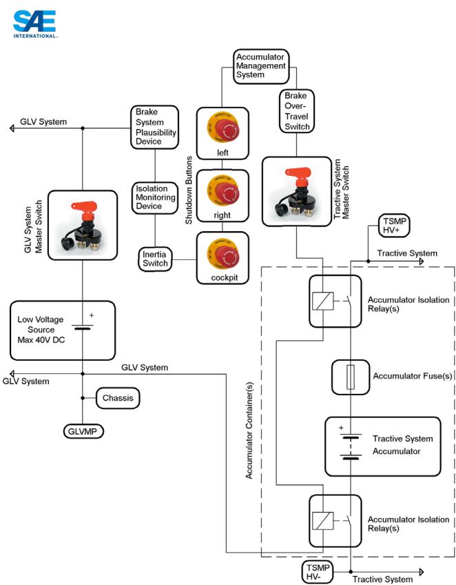
EV5.3 Shutdown Buttons
EV5.3.1 A system of three shut-down buttons must be installed on the vehicle.
EV5.3.2 Pressing any one of the shut-down buttons must separate the tractive system from the accumulator block by opening the shutdown circuit, see also EV5.1.
|
103 |
© 2013 SAE International. All Rights Reserved |
2014 Formula SAE Rules |

EV5.3.3 Each shut-down button must be a push-pull or push-rotate emergency switch where pushing the button opens the shutdown circuit. The shut-down buttons must not act through programmable logic.
EV5.3.4 One button must be located on each side of the vehicle behind the driver’s compartment at approximately the level of the driver’s head. The minimum allowed diameter of the shutdown buttons on both sides of the car is 40 mm. The international electrical symbol consisting of a red spark on a white-edged blue triangle must be affixed in close proximity to this button.
EV5.3.5 One shutdown button serves as a cockpit-mounted Master Switch. The minimum allowed diameter of the shutdown button in the cockpit is 24 mm. The international electrical symbol consisting of a red spark on a white-edged blue triangle must be affixed in close proximity to this switch. It must be located to provide easy actuation by the driver in an emergency or panic situation. It must be located within easy reach of the belted-in driver, alongside the steering wheel, and unobstructed by the steering wheel or any other part of the car.
EV5.3.6 The shutdown buttons are not allowed to be easily removable, e.g. they must not be mounted onto removable body work.
EV5.4 Brake-Over-Travel-Switch
The Brake-Over-Travel-Switch as defined in T7.3 must shut down the tractive system by activating the shutdown circuit and opening the AIRs, see EV5.1.
EV5.5 Insulation Monitoring Device (IMD)
EV5.5.1 Every car must have an insulation monitoring device (IMD) installed in the tractive system.
EV5.5.2 The IMD needs to be a Bender A-ISOMETER ® iso-F1 IR155-3203 or -3204 or equivalent IMD approved for automotive use. Equivalency may be approved by the rules committee based on the following criteria: robustness to vibration, operating temperature range, IP rating, availability of a direct output, a self-test facility and must not be powered by the system which is monitored.
EV5.5.3 The response value of the IMD needs to be set to 500 Ohm / Volt, related to the maximum tractive system operation voltage.
EV5.5.4 In case of an insulation failure or an IMD failure, the IMD must open the shutdown circuit. This must be done without the influence of any programmable logic. See also EV5.1.4 and EV5.1.5 regarding the re-activation of the tractive-system after an insulation fault.
EV5.5.5 The status of the IMD must be shown to the driver by a red indicator light in the cockpit that is easily visible even in bright sunlight. This indicator must light up, if the IMD detects an insulation failure or if the IMD detects a failure in its own operation e.g. when it loses reference ground.
The IMD indicator light must be clearly marked with the lettering “IMD”.
EV5.6 Brake System Plausibility Device
A standalone non-programmable circuit must be used on the car such that when braking hard (without locking the wheels) and when a positive current is delivered from the motor controller (a current to propel the vehicle forward), the AIRs will be opened. The current limit for triggering the circuit must be set at a level where 5kW of electrical power in the DC circuit is delivered to the motors at the nominal battery voltage. The action of opening the AIRs must occur if the implausibility is persistent for more than 0.5sec. This device must be provided in addition to the plausibility checks which are
|
104 |
© 2013 SAE International. All Rights Reserved |
2014 Formula SAE Rules |

carried out by the controller which interprets the drivers torque request and delivers torque to the wheels. The Brake Plausibility Device may only be reset by power cycling the GLVMS.
The team must devise a test to prove this required function during Electrical Tech Inspection. However it is suggested that it should be possible to achieve this by sending an appropriate signal to the non-programmable circuit that represents the current to achieve 5kW whilst pressing the brake pedal to a position or with a force that represents hard braking.
EV5.7 Inertia Switch
EV5.7.1 All vehicles must be equipped with an inertia switch. This must be a Sensata Resettable Crash Sensor or equivalent.
EV5.7.2 The inertia switch must be part of the shutdown circuit and must be wired in series with the shutdown buttons such that an impact will result in the shutdown circuit being activated and the AIRs being opened. The inertia switch must latch until manually reset.
EV5.7.3 The device must trigger due to an impact load which decelerates the vehicle at between 6g and 11g depending on the duration of the deceleration (see spec sheet of the Sensata device).
EV5.7.4 The inertia switch may be reset by the driver from within the driver's cell.
EV5.7.5 The device must be mechanically attached to the vehicle, however it must be possible to demount the device so that its functionality can be tested by shaking it.
ARTICLE 6: FUSING
EV6.1 Fusing
EV6.1.1 All electrical systems (both low and high voltage) must be appropriately fused.
The continuous current rating of a fuse must not be greater than the continuous current rating of any electrical component, for example wire, busbar, cell or other conductor that it protects.
EV6.1.2 All fuses and fuse holders must be rated for the highest voltage in the systems they protect. Fuses used for DC must be rated for DC, and must carry a DC rating equal to or greater than the system voltage.
EV6.1.3 All fuses must have an interrupt current rating which is higher than the theoretical short circuit current of the HV system that it protects.
EV6.1.4 If multiple parallel strings of batteries or capacitors are used then each string must be individually fused to protect all the components on that string. Any conductors, for example wires, busbars, cells etc conducting the entire pack current must be appropriately sized for the total current that the individual fuses could transmit or an additional fuse must be used to protect the conductors.
EV6.1.5 Battery packs with low or non-voltage rated fusible links for cell connections may be used provided that:
1.A fuse rated at a current three times lower than the sum of the parallel fusible links and complying with Section EV6.1.1 is connected in series, and
2.The accumulator monitoring system can detect an open fusible link, and will shut down the electrical system by opening HV contactors if a fault is detected.
3.Fusible link current rating is specified in manufacturer’s data or suitable test data is provided.
|
105 |
© 2013 SAE International. All Rights Reserved |
2014 Formula SAE Rules |
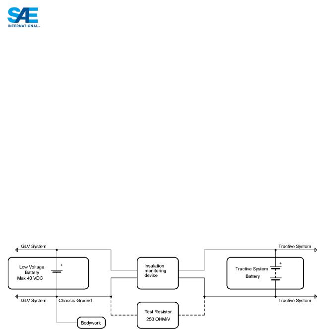
EV6.1.6 Cells with internal over-current protection may be used without external fusing or fusible-links if suitably rated.
NOTE: Most cell internal over-current protection devices are low or non-voltage rated and conditions of EV6.1.6 will apply.
EV6.1.7 The ESF must include all details of fuse and fuseable link and internal over current protection including documentation from manufacturer for the particular series and parallel configuration, and string voltage.
ARTICLE 7: ELECTRICAL SYSTEM TESTS
EV7.1 Insulation Monitoring Device Test (IMDT)
EV7.1.1 The insulation monitoring device will be tested during Electrical Tech Inspection. This is done by connecting a resistor between the measuring points, see EV4.5, of the tractive system and several electrically conductive vehicle parts while the tractive system is active, as shown in the example below.
EV7.1.2 The test is passed if the IMD shuts down the tractive system within 30 seconds at a fault resistance of 50% below the response value corresponding to 250 Ohm / Volt.
EV7.1.3 The IMDT may be repeated at any time during the event. After the car passes the test for the first time, critical parts of the tractive system will be sealed. The vehicle is not allowed to take part in any dynamic event if any of the seals are broken until the IMDT is successfully passed again.
EV7.2 Insulation Measurement Test (IMT)
EV7.2.1 The insulation resistance between the tractive system and GLV system ground will be measured during Electrical Tech Inspection. The available measurement voltages are 250V and 500V. All cars with a maximum nominal operation voltage below 500V will be measured with the next available voltage level e.g. a 175V system will be measured with 250V, a 300V system will be measured with 500V etc. All teams with a system voltage of 500V or more will be measured with 500V.
EV7.2.2 To pass the IMT the measured insulation resistance must be at least 500 Ohm/Volt related to the maximum nominal tractive system operation voltage.
EV7.3 |
Rain test |
|
EV7.3.1 |
Teams have to pass a rain test during Electrical Tech Inspection to be allowed to move the car under |
|
|
its own power on the event. The car must pass the IMDT, see EV7.1, before the rain test can be |
|
|
performed. |
|
|
|
106 |
© 2013 SAE International. All Rights Reserved |
2014 Formula SAE Rules |
|

EV7.3.2 During the rain test the tractive system must be active and none of the driven wheels may touch the ground. The car must NOT be in ready-to-drive-mode. It is not allowed to have a driver seated in the car during the rain test.
Water will then be sprayed at the car from any possible direction for 120 seconds. The water spray will be rain like. Therefore there will be no direct high-pressure water jet shot at the car.
EV7.3.3 The test is passed if the insulation monitoring device does not react while water is sprayed at the car and 120 seconds after the water spray has stopped. Therefore the total time of the rain test is 240 seconds, 120 seconds with water-spray and 120 seconds without.
EV7.3.4 Teams have to make sure that water cannot aggregate anywhere in the chassis.
ARTICLE 8: HIGH VOLTAGE PROCEDURES & TOOLS
EV8.1 Working on Tractive System Accumulator Containers
EV8.1.1 Opening of or working on accumulator containers is only allowed in the charging area, see EV8.2, and during Electrical Tech Inspection.
EV8.1.2 Whenever the accumulator containers are opened the cell segments have to be separated by using the maintenance plugs, see EV3.3.3.
EV8.1.3 Whenever the Accumulator or tractive system is being worked on, only appropriate insulated tools may be used.
EV8.1.4 Safety glasses with side shields must be worn by all participating team members when (a) parts of the tractive system are exposed while it is active, or (b) work is being done on the accumulators.
EV8.2 Charging
EV8.2.1 There will be a separated charging area on the event site. Charging tractive system accumulators is only allowed inside this area.
EV8.2.2 Accumulators may be charged inside the car.
EV8.2.3 It is also possible to charge the accumulators outside the car with a removable accumulator container.
EV8.2.4 The accumulator containers or the car itself, depending on whether the accumulators are charged externally or internally, must have a label with the following data during charging: Team name and Electrical System Officer phone number(s).
EV8.2.5 NO WORK IS ALLOWED ON ANY OF THE CAR'S SYSTEMS DURING CHARGING, IF THE ACCUMULATORS ARE CHARGED INSIDE THE CAR.
EV8.2.6 No grinding, drilling, etc. is allowed in the charging area.
EV8.2.7 At least one team member who has knowledge of the charging process must stay with the accumulator(s) / car during charging.
EV8.2.8 Moving accumulator cells and/or accumulator segment(s) around at the event site is only allowed inside a completely closed accumulator container.
|
107 |
© 2013 SAE International. All Rights Reserved |
2014 Formula SAE Rules |

EV8.3 Chargers
EV8.3.1 Only chargers presented and sealed at Electrical Tech Inspection are allowed. All connections of the charger(s) must be isolated and covered. No open connections are allowed.
EV8.3.2 All chargers must either be accredited to a recognized standard eg. CE or where built by the team they must be built to high standards and conform with all electrical requirements for the vehicle tractive system, for example EV4.1, EV4.4 and EV4.6 as appropriate.
EV8.3.3 The charger must incorporate an interlock such that the connectors only become live if is correctly connected to the accumulator.
EV8.3.4 HV charging leads must be orange
EV8.3.5 When charging, the AMS must be live and must be able to turn off the charger in the event that a fault is detected.
EV8.3.6 The charger must include a push type emergency stop button which has a minimum diameter of 25mm and must be clearly labeled.
EV8.4 Accumulator Container Hand Cart
EV8.4.1 In case removable accumulator containers are used in order to accommodate charging, a hand cart to transport the accumulators must be presented at Electrical Tech Inspection.
EV8.4.2 The hand cart must have a brake such that it can only be released using a dead man's switch, i.e. the brake is always on except when someone releases it by pushing a handle for example.
EV8.4.3 The brake must be capable to stop the fully loaded accumulator container hand cart.
EV8.4.4 The hand cart must be able to carry the load of the accumulator container(s).
EV8.4.5 The hand cart(s) must be used whenever the accumulator container(s) are transported on the event site.
EV8.5 Each team must present the following basic set of tools in good condition during technical inspection:
-Insulated cable shears
-Insulated screw drivers
-Multimeter with protected probe tips
-Insulated tools, if screwed connections are used in the tractive system
-Face Shield
-HV insulating gloves which are within test date
-2 HV insulating blankets of at least 1.0m² each
-Safety glasses with side shields for all team members that might work on the tractive system or accumulator
All electrical safety items must be rated for at least the maximum tractive system voltage.
|
108 |
© 2013 SAE International. All Rights Reserved |
2014 Formula SAE Rules |

ARTICLE 9: ELECTRICAL SYSTEM FORM AND FMEA
EV9.1 Electrical System Form (ESF)
EV9.1.1 Prior to the event all teams must submit clearly structured documentation of their entire electrical system (including control and tractive system) similar to the SEF called electrical system form (ESF).
EV9.1.2 The ESF must visualize the interconnection of all electric components including the voltage level, the topology, the wiring in the car and the construction and build of the accumulator(s).
EV9.1.3 Teams must present data sheets with rated specifications for all tractive system parts used and show that none of these ratings are exceeded (including wiring components). This includes stress caused by the environment e.g. high temperatures, vibration, etc.
EV9.1.4 A template including the required structure for the ESF will be made available online – see website for your competition or www.fsaeonline.com.
EV9.1.5 The ESF must be submitted as Adobe PDF-File.
EV9.1.6 The minimum allowed font size is 11pts. The font used must be Arial. Small pictures and small schematics should be put inside the text for easy reference, not in the appendix.
EV9.1.7 Data sheets and large schematics should be put in the appendix.
NOTE: Passing the ESF does not mean that you automatically pass Electrical Technical Inspection with the described items / parts.
EV9.2 Failure Modes and Effects Analysis (FMEA)
EV9.2.1 Teams must submit a complete failure modes and effects analysis (FMEA) of the tractive system prior to the event.
EV9.2.2 A template including required failures to be described will be made available online – see your competition website for details.
Do not change the format of the template. Pictures, schematics and data sheets to be referenced in the FMEA have to be included in the FMEA on additional table pages
EV9.3 Submission of the ESF or FMEA
Electrical Systems Form (ESF) or Failure Modes and Effects Analysis (FMEA) must be submitted in compliance with the procedure and by the deadline published on the website of the competition your team is attending.
EV9.4 Penalty for Late Submission or Non-submission
Late submission of either the ESF or FMEA will be penalized at the standard negative ten (-10) points per whole or partial day after the deadline to a maximum of negative fifty (-50) points.
|
109 |
© 2013 SAE International. All Rights Reserved |
2014 Formula SAE Rules |

2014 FORMULA SAE
PART S - STATIC EVENT REGULATIONS
ARTICLE 1: STATIC EVENTS AND MAXIMUM SCORES
The maximum possible scores in the static events are:
Technical Inspection |
No Points |
|
Cost and Manufacturing |
100 Points |
|
Presentation |
75 Points |
|
Design |
150 Points |
|
Total |
325 Points |
|
ARTICLE 2: TECHNICAL INSPECTION
S2.1 Objective of Technical Inspection
The objective of technical inspection is to determine if the vehicle meets the FSAE Rules requirements and restrictions and if, considered as a whole, it satisfies the intent of the Rules.
S2.1.1 For purposes of interpretation and inspection the violation of the intent of a rule is considered a violation of the rule itself. (See Rule A3.6)
S2.1.2 Technical inspection is a non-scored activity.
S2.2 Inspection & Testing Requirement
Each vehicle must pass all parts of technical inspection and testing, and bear the inspection stickers, before it is permitted to participate in any dynamic event or to run on the practice track.
S2.2.1 All items on the Inspection Form must be clearly visible to the technical inspectors.
S2.2.2 Visible access can be provided by removing body panels or by providing removable access panels.
S2.3 Team Responsibility
Teams are responsible for confirming that their vehicle, and the required equipment, satisfies the requirements and restrictions of the FSAE Rules before presenting it for Technical Inspection.
S2.3.1 Presenting a vehicle for Technical Inspection constitutes a declaration by the team that they have determined by self inspection that the vehicle complies with the Rules.
S2.4 Items to be Inspected
The following items must be brought to Technical Inspection:
•Vehicle
•Technical Inspection Form
•Dry and wet tires
•Driver’s equipment - for all drivers including arm restraints, helmets, suits, gloves, eye protection, balaclavas, socks and shoes.
•Fire extinguishers
•Push bar
•Structural Equivalency Spreadsheet (SES) copies or Structural Requirements Certification Form (SRCF) copies, as appropriate for your car.
|
110 |
© 2013 SAE International. All Rights Reserved |
2014 Formula SAE Rules |
•Impact Attenuator Report copies
•Electric cars only: Electrical System Form
•Electric cars only: FMEA
•Copies of any rules questions you submitted with the answer you received.
•All drivers must be present at inspection.
S2.5 Technical Inspection Procedure
Technical inspection will examine all items included on the Inspection Form found on the SAE website plus any other items the inspectors may wish to examine to ensure conformance with the Rules. The exact procedures and instruments employed for inspection and testing are entirely at the discretion of the Chief Technical Inspector.
S2.5.1 Decisions of the inspectors and the Chief Technical Inspector concerning vehicle compliance are final and are not permitted to be appealed.
S2.6 Inspection Condition
Vehicles must be presented for technical inspection in finished condition, i.e. fully assembled, complete and ready-to-run. Technical inspectors will not inspect any vehicle presented for inspection in an unfinished state.
Note: Cars may be presented for technical inspection even if final tuning and set-up has not been finished.
S2.7 Inspection Process
Vehicle inspection will consist of three separate parts as follows:
S2.7.1 Part 1 – Electrical and Mechanical Scrutineering
EVs have to pass electrical Scrutineering first, before being allowed to attend mechanical Scrutineering. EVs may only be moved around the event site with the HVD disconnected until they have passed electrical Scrutineering. This includes participation in any static events.
Each vehicle will be inspected to determine if it complies with the requirements of the rules. This inspection will include examination of the driver’s equipment (Part T Article 14) and a test of the driver egress time (Rule T4.8).
Part 1 must be passed before a vehicle may apply for Part 2 and Part 3 inspection.
S2.7.2 Part 2 – Tilt Table Tests
Each vehicle will be tested to insure it satisfies both the forty-five degree (45°) fuel and fluid tilt requirement (Rule T8.5) and the sixty degree (60°) rollover stability requirement (Rule T6.7.2).
Parts 1 and 2 must both be passed before a vehicle may apply for Part 3 inspection.
S2.7.3 Part 3 – Noise, Master Switch, Ready-To-Drive-Sound, Rain Test and Brake Tests
IC Vehicles - Noise will be tested by the specified method (Rule IC3.2). If the vehicle passes the noise test then its master switches (Rule IC4.1) will be tested.
EV Vehicles - If the vehicle is an EV, the Ready-To-Drive-Sound Test (EV4.14.3) will be conducted instead of the Noise and Master Switch tests. If the vehicle passes both the noise and master switch or
|
111 |
© 2013 SAE International. All Rights Reserved |
2014 Formula SAE Rules |

the Ready-To-Drive-Sound tests respectively then the rain test (EV 7.3) will be performed before its brakes will be tested by the specified method (Rule T7.2).
S2.8 Correction and Re-inspection
S2.8.1 If any part of a vehicle does not comply with the Rules, or is otherwise deemed to be a concern, then the team must correct the problem and have the car re-inspected.
S2.8.2 The judges and inspectors have the right to re-inspect any vehicle at any time during the competition and require correction of non-compliance.
S2.9 Inspection Stickers
Inspection stickers issued following the completion of any part of Technical Inspection will be placed on the upper nose of the vehicle as specified in Rule T13.4 “Technical Inspection Sticker Space”.
S2.9.1 Inspection stickers are issued contingent on the vehicle remaining in the required condition throughout the competition.
S2.9.2 Inspection stickers may be removed from vehicles that are not in compliance with the Rules or are required to be re-inspected.
S2.10 “As-Approved Condition”
Once a vehicle has passed inspection, except as specifically allowed under Rule T1.2 “Modification and Repairs”, it must remain in the “As-approved” condition throughout the competition and must not be modified.
S2.11 Inspection Validity
Technical approval is valid only for the duration of the specific Formula SAE competition during which the inspection is conducted.
ARTICLE 3: BUSINESS LOGIC CASE
S3.1 The Objectives of the Business Logic Case are to:
(a)Teach participants about the factors that need to be considered when a company embarks on development of a new product. These include: cost; identification of market and likely sales volume; profitability; the key features applicable to the selected vehicle concept and target market size.
(b)Ensure teams develop the concept of their entry with all of these aspects correctly considered, from the outset.
(c)Ensure that all three static events are approached with a single common concept and presented to each set of static judges in the same manner.
(d)Ensure that participants gain experience in producing a business case and balancing potentially conflicting attributes.
S3.2 The Design, Cost and Business Presentation judges will use the business logic case to verify that the information presented at each static event is consistent with the overall objectives as outlined in the Static Events Rules.
(a)In the Design event, the business logic case will be used to identify how the team determined the trade-off between design for performance and design for manufacture and cost, how these requirements were considered in the overall concept and whether these were achieved in the final vehicle.
|
112 |
© 2013 SAE International. All Rights Reserved |
2014 Formula SAE Rules |

(b)In the Cost event, the business logic case will be used to determine that the cost target was met for the same design solution and how Cost was integrated into the overall concept and the iterative design process.
(c)In the Business Presentation event, the business logic case will be used to assess whether the business presentation is appropriate for the market and business strategy that the team has identified
(d)For some Formula Student/FSAE Events, if the event is over subscribed, then the entry selection process may include assessment of the quality of the Business Logic Case supplied.
S3.3 All teams must submit a Business Logic Case report in accordance with the general format applicable for the year of competition “FSAE Business Logic Case 201X”. The report must be submitted on the template. Refer to the applicable competition website to acquire the template.
This report must be submitted by the deadline which will generally be ~ 6-9 months before the competition. Refer to the deadlines posted on the website for each specific competition.
ARTICLE 4: COST AND MANUFACTURING EVENT
Important Notice: Additional information about the Cost and Manufacturing Event including Cost Tables and other information can be obtained from the www.fsaeonline.com website which is also linked off the Formula SAE Rules and Important Documents page on the FSAE Website.
S4.1 Event Objective
The objectives of the Cost and Manufacturing Event are:
a.To teach the participants that cost and budget are significant factors that must be considered in any engineering exercise.
b.For teams to make trade off decisions between content and cost based on the performance advantage of each part and assembly.
c.To gain experience with creating and maintaining a Bill of Material (BOM).
d.For the participants to learn and understand the principles of Design for Manufacture and Assembly, lean manufacturing and Minimum Constraint Design.
S4.2 Rules Objective
The objectives of the Cost and Manufacturing Event rules are:
a.To provide a logical, simple and time efficient rule set enabling students to achieve the event’s objectives.
b.To improve fairness by providing consistent pricing guidelines independent of team geographical location by using standardized Cost Tables.
c.To require the minimal burden of supporting documentation such as receipts or catalog pages. However, in order to convey design information to cost judges engineering documentation (drawings, process descriptions, etc) are required.
S4.3 Event Requirements
This event is comprised of three (3) parts
S4.3.1 Part 1 “Cost Report”
The preparation and submission of a report (the “Cost Report”), which is to be sent to the Cost Judges prior to the competition. See S4.1.
S4.3.2 Part 2 “Discussion”
|
113 |
© 2013 SAE International. All Rights Reserved |
2014 Formula SAE Rules |

|
A discussion at the Competition with the Cost Judges around the team’s vehicle. This evaluates not |
|
|
only the cost of the car, but also the team’s ability to prepare accurate engineering and manufacturing |
|
|
cost estimates. |
|
S4.3.3 |
Part 3 “Real Case” |
|
|
A “real case” scenario where students will have to respond to a challenge related to cost or |
|
|
manufacturing of the student vehicle. |
|
S4.4 |
Formula SAE Michigan & Formula SAE Lincoln Reports |
|
|
Teams that are entering more than one North American competition may submit one (1) Cost Report |
|
|
covering all the competitions entered providing that (a) the report properly identifies the competition |
|
|
names and car numbers and (b) any addenda necessary to cover changes or modifications made to the |
|
|
vehicle between events is properly completed and submitted. |
|
S4.5 |
Public Cost Reports |
|
|
By submitting a cost report to the competition’s organizing body for judging you and your team agree |
|
|
that your cost report can be reproduced and distributed by the competition organization, in both |
|
|
complete and edited versions, in any medium or format anywhere in the world. |
|
|
Note: Beginning with the 2013 competition season it is the plan of the FSAE Rules Committee and |
|
|
the competition organizers to publish all cost reports, in as-submitted format, to the FSAE website. It |
|
|
is the intent of this move to make the cost event more transparent and improve the educational |
|
|
experience of the students by providing the full range of cost reports for teams to review. Cost reports |
|
|
for a given competition season will not be published before the end of the calendar year. Support |
|
|
materials, such as technical drawings, will not be released. |
|
S4.6 |
Definitions |
|
|
The following definitions will apply throughout the Cost Event rules: |
|
S4.6.1 |
Adjusted Cost – The final cost for the vehicle including penalties |
|
S4.6.2 |
Amended Cost – The cost of the vehicle after modification by the competition addendum |
|
S4.6.3 |
Bill of Material – A hierarchical list of all parts of the vehicle. A BOM lists every item that is on the |
|
|
vehicle but also shows the relationships between these items, for example showing the parts that make |
|
|
up an assembly. A Costed Bill of Material (CBOM) is a standard BOM that includes cost information |
|
|
including cost of purchased parts, raw materials and processes that go into manufacturing the vehicle. |
|
S4.6.4 |
Category - Each table has numerous entries which describe a classification of entry. |
|
|
For example there are several types of hose clamps, and all have various costs. The category of hose |
|
|
clamp may be worm drive, constant tension, etc. |
|
S4.6.5 |
Cost – The cost for each item from the materials table is simply the quantity multiplied by the unit |
|
|
cost. |
|
S4.6.6 |
Cost Report – All materials, including electronic and hard copy, submitted for judging |
|
S4.6.7 |
Cost Score – Refers to the total number of points out of 100 earned in the Cost Event |
|
S4.6.8 |
Cost Tables – All tables that list costs for objects and processes |
|
|
114 |
|
© 2013 SAE International. All Rights Reserved |
2014 Formula SAE Rules |
|

S4.6.9 Design for Manufacture and Assembly (DFMA) – The process where parts are designed for ease of manufacture and assembly, resulting in lower cost.
S4.6.10 Fasteners Table – A Cost Table that consists of not only traditional fasteners such as bolts, nuts and rivets but also adhesives, hose clamps and retaining rings.
S4.6.11 Fixed Cost – Costs associated with production that are independent of volume produced. Fixed cost items, such as tooling, are converted to variable costs when included in the Cost Report.
S4.6.12 Initial Cost – The cost of the vehicle submitted for initial judging in the Cost Report.
S4.6.13 Lean Manufacture – A methodology for producing goods that emphasizes the elimination of waste and improvement in process flow with the goal of optimizing the cost and quality of goods.
S4.6.14 Materials Table – Lists the costs for raw materials used to manufacture parts built by the teams and also of finished parts purchased by the teams.
S4.6.15 Minimum Constraint Design (MCD) – A design methodology emphasizing elimination of redundant constraints in the attachment of parts. Each part requires constraint in six degrees of freedom and additional constraints can make assembly difficult, force tight tolerances and increase the cost of manufactured goods.
S4.6.16 Parameters – Used to create an equation describing the cost of an object as a function of some characteristic of that object. For example the cost of steel is proportional to the mass (or volume) of steel. In this case steel has been parameterized by mass. Rubber hose could be parameterized by diameter. The equations can be linear or non-linear and both 1st and 2nd order equations are used as necessary to build the Cost Tables.
S4.6.17 Process Multipliers - Modify the standard costs of different operations to account for material and geometric differences in the part.
S4.6.18 Purchased Parts – Also called bought parts; these items are listed in the Cost Tables in a near asinstalled condition. For example wheels, engines and turbochargers are purchased parts. In some cases purchased parts may still require additional processing before they can be assembled to the car. Wheels, for example, do not include the machined features for mounting to the hub. Purchased parts do not include fasteners unless specifically noted in the Cost Tables.
S4.6.19 Quantity – The amount of the item
S4.6.20 Raw Materials – Materials used for manufacturing parts, such as aluminum, steel and rubber hose.
S4.6.21 Tools – Tools refer to hand or power tools used to assemble the vehicle. The costs of these tools are not included in the Cost Report. The effect of the tools used for assembly are captured in the process tables for labor as different costs are given based on the tools used for assembly.
S4.6.22 Tooling - Is the production tooling associated with processes that are specific to the part geometry. The costs of tooling must be included in the Cost Report. For example the dies to stamp out a chassis bracket are tooling. The press used to stamp the bracket is not, and is considered production equipment which is not part of the Cost Event.
S4.6.23 Unit – Is the measurement system used to define the quantity of a parameter.
|
115 |
© 2013 SAE International. All Rights Reserved |
2014 Formula SAE Rules |

For example millimeters and kilograms are units. The hose clamp diameter unit is mm. When calculating the cost of the clamp the unit of measurement used by the team must match the Unit specified in the tables. For example a US team mistakenly calculates the hose clamp cost by using the expression with a diameter of 1, because their radiator hose is 1 inch in diameter. They should have used 25.4mm for the diameter and their cost is wrong because of it. For the penalties associated with this type of error see S4.19
S4.6.24 Unit Cost – Is the cost for something assuming a numerical value of one (1) of the unit used to measure the item. The cost is the quantity of an item multiplied by the unit cost.
S4.6.25 Variable Cost – Is a cost associated with production that is proportional to the vehicle volume produced. All costs submitted with the Cost Report will be variable costs.
S4.7 General Requirements
S4.7.1 The Cost Report must:
a.Use the standardized Cost Tables. The tables are designed to reflect a hypothetical car built for production at the annual volume of 1000 units per year.
b.List and cost every part on the prototype vehicle. This includes any equipment fitted on the vehicle at any time during the competition. The only exceptions are that, per S4.23 “Cost Report Exempt Items” of the Rules, the cost of any finish, on-board fire suppression system, rain tires, video or radio system, does not need to be included in the Cost Report.
c.Be based on the estimated costs of materials, fabrication, purchased parts, and assembly of the car. The costs shall be calculated as defined in these rules.
d.Be based on the actual manufacturing technique used on the prototype, e.g. cast parts on the prototype must be cost as cast, and fabricated parts as fabricated, etc.
e.Include tooling (e.g. welding jigs, molds, patterns and dies) for processes requiring it.
f.Exclude R & D and capital expenditures (e.g. plant, machinery, hand tools and power tools).
Note: There is no maximum cost. Receipts are not required for any items.
S4.7.2 The Cost Tables have been designed to:
a.Be verifiable at the event. Differentiating between different types of materials (for example different alloys of steel) is not possible so no differentiation is made in the table cost.
b.Minimize influence on safety equipment content. For example driver harnesses are cost independent of the style chosen.
c.Higher costs of some goods must reflect actually higher value of those goods. However, the costs must still allow for team innovation and vehicle content, with some reduction in cost score.
S4.8 |
Scoring |
|
|
|
The points for the Cost and Manufacturing Event will be broken down as follows: |
||
|
40x[(Pmax)/(Pyour)-1] |
40 Points |
Lowest cost - each of the participating schools will be ranked |
|
[(Pmax)/Pmin)-1] |
|
by total adjusted cost from the BOM and given 0-40 points |
|
|
|
based on the formula on the left. |
|
|
40 Points |
Accuracy, Clarity & Event Day/Visual Inspection - The cars |
|
|
|
will be reviewed for part content, manufacturing feasibility and |
|
|
|
accuracy of the cost information. Supporting documentation |
|
|
|
will be assessed based on its quality, accuracy and |
|
|
|
thoroughness. The range for the score is 0-40 points. |
|
|
20 Points |
Event Day/Manufacturing Processes - The teams must be |
|
|
|
prepared to discuss in detail the “real case” scenario distributed |
|
|
|
116 |
© 2013 SAE International. All Rights Reserved |
2014 Formula SAE Rules |
||
prior to the competition. The materials will include more specifics about the goal and scoring of the scenario. The range for the score is 0-20 points.
Total |
100 Points |
Where:
Pyour is the adjusted cost of your car (with penalties) in dollars.
Pmin is the adjusted cost of the lowest cost car in dollars.
Pmax is the cost of the highest cost car in dollars.
S4.9 Cost Report
S4.9.1 The Cost Report consists of a full vehicle BOM with cost data derived from the Cost Tables and supporting documentation. The Cost Report must be submitted in two (2) forms:
a.Electronic Version – The upload of the electronic cost report has to be done in these steps:
1.Upload of the vehicle BOM as Microsoft Excel ® file (.xls or .xlsx)
2.Upload of the supporting material as one separate PDF file (.pdf)
The electronic version of the two files must be identified as follows:
Carnumber_schoolname_competitioncode_CR_BOM.xls using the assigned car number, the complete school name and the competition code.
Example: 087_University of FSAE_FSAEM_CR_BOM.xls
Carnumber_schoolname_competitioncode_CR_Supplement.pdf using the assigned car number, the complete school name and the competition code for the BOM.
Example: 087_University of FSAE_FSAEM_CR_Supplement.pdf
Competition Codes are listed in Rule A2.6
b.Hard Copy – The hard copy Cost Report must be in a ring binder with 8.5” x 11” or A4 pages including both the BOM and supporting documentation (Annex).
c.A complete submission includes all portions of the electronic cost report and the hard copy. The electronic version of the Cost Report must be submitted via fsaeonline.com. The
hard copy must be mailed to the address posted on sae.org. The hard copy must also include a copy of the electronic files on a memory stick or CD.
Note: Some competitions may waive the hard copy requirement. If so, the waiver will be published on the SAE website. Also note that the electronic submission has been broken into multiple parts to enable the BOM to be posted per rule S4.5 without posting the supporting documentation.
S4.9.2 Cost Report Identification
The cover of the Cost Report must include the following:
(a) university name, (b) competition name, and (c) vehicle number.
Note: Teams that are submitting a single Cost Report covering more than one North American competition must identify their report as follows:
University Name (full name)
Formula SAE Michigan, Car # XXX and Formula SAE Lincoln, Car #YYY
S4.9.3 The Cost Report must consist of the following:
|
117 |
© 2013 SAE International. All Rights Reserved |
2014 Formula SAE Rules |

•A Cover sheet
•A Table of Contents
•A Cost Summary page listing each section’s cost, and the total vehicle cost
•Eight commodity report sections with the parts placed in the sections as specified in Appendix S-3.
•Tabs for each section
S4.10 Bill of Materials (BOM)
The BOM is a parts list for every vehicle part. It also shows the relationships between the items.
S4.10.1 The following terminology will be used when referring to the BOM.
•The overall vehicle is broken down into eight (8) systems which are defined in Appendix S-3.
•Systems are made up of Assemblies.
•Assemblies are made up of Parts.
•Parts consist of materials, processes and fasteners.
•Tooling is associated with each process that requires production tooling.
S4.10.2 An example BOM structure is shown below:
•Engine & Drivetrain…………………………… System o Engine……………………………………... Assembly o Differential………………………………… Assembly
Housing…………………………..…… Part
Aluminum……………………….… Material
Needle Bearing…………...……… Material
Sand cast………………….……… Process
• Die & Core Package #4…..… Tooling
Machining-Turn………………...... Process
Weld………………………….…… Process
M6x1.25 Grade 8.8……………… Fastener
Internals………………………….…… Part
End Cap……………………….……… Part
The BOM must follow the format given above. There must be no other BOM levels added or any removed. Deviations from the structure published will be penalized per Section S4.18.
S4.10.3 All assemblies, parts and fasteners in the BOM must use a standard numbering convention explained in Appendix S-2.
S4.11 The Cost Tables
S4.11.1 All costs in the Cost Report come from the standardized Cost Tables. These tables have been compiled to represent the cost of parts and processes that a manufacturing company could be expected to pay for manufacturing a vehicle at 1000 units per year. Generally, the tabulated value represents ½ of the Manufacturer’s Suggested Retail Price (MSRP) for finished parts. Raw materials, commodities and fasteners also intended to represent the production volume of a company rather than the purchase price of the University teams.
S4.11.2 Requests to alter the cost of goods in the tables because of changing world markets or individual team purchase price will not be approved. The tables are intended to provide a fair, unchanging (within a given competition year) cost for parts and to reduce regional variations in price that may help or hurt
|
118 |
© 2013 SAE International. All Rights Reserved |
2014 Formula SAE Rules |

certain teams. All teams must use the costs given in the tables. If a team wishes to use any parts, processes or materials not included in the tables an “Add Item Request” must be submitted as per Section S4.14.
S4.11.3 The tables represent cost based on specific parameters. For example the cost of steel is given per unit of volume (or mass). Likewise, engine costs are listed by displacement and specific power output.
S4.11.4 The following Cost Tables are used
•Materials
•Processes
•Process Multipliers
•Fasteners
•Tooling
S4.11.5 In general, most items have a cost expressed as a function of one parameter. In cases where more than one parameter is necessary additional categories are listed. For example the power output of the engine has three Categories and for each Category a different expression calculates the cost as a function of the engine displacement, which is the Parameter. The Unit would be cubic centimeters in this case.
S4.11.6 Process Multipliers are used to modify the standard costs of different operations to account for material and geometric differences in the part. For every process included in the Cost Report the list of process multipliers must be checked to determine if any apply, and if they do their effect on the cost must be included.
S4.11.7 When adding items from tables to the BOM the comments section should be reviewed thoroughly to understand what is included in the table entry. For example is the spring included in the damper cost? Do the spark plugs come with the engine or are they a separate line item? In cases where the explanation is not clear please contact the Rules Committee for clarification.
S4.12 Cost Models & Costing Methodology
The cost models are the underlying methodology and equations that relate the final cost of a part or process to the different operations and goods used in that part. The detailed explanation of the Cost Models and Costing Methodology is included in Appendix S-1 and should be referenced for understanding the use of the Cost Tables.
S4.13 Make Versus Buy
Every part on an individual car can be classified as “made” or “bought”. This designation does not necessarily refer to whether a team actually purchased or fabricated a part but is a reflection of how the part must be cost from the Cost Tables.
a.Made (or manufactured) parts must be cost as if the company manufacturing the vehicle was going to make the part internally. That is by purchasing raw materials and processing them into a finished product.
b.Bought parts must be cost as if the company manufacturing the vehicle was going to outsource the fabrication of that part. These parts would be received by the vehicle manufacturer in a relatively finished state (see the particular table entry comments field for specific information).
S4.13.1 The Cost Tables have been constructed as a tradeoff between complexity for the organizers and fairness for the teams. The make versus buy designation enables certain parts to be simplified to a relatively few number of entries. For example some teams may purchase axles but the majority of teams manufacture them. Axles are designated “make” parts so teams that purchase axles must cost
|
119 |
© 2013 SAE International. All Rights Reserved |
2014 Formula SAE Rules |

them as if they had made them starting with the raw materials, in this case probably steel tubing. Made parts can be distinguished because they do not appear explicitly in the Cost Tables or appear with a “cost as made” option.
S4.13.2 If a team genuinely makes a part listed on the table as a bought part they may alternatively cost it as a made part if and only if a place holder entry is listed in the tables enabling them to do so. For example, in the category of dampers a “student built” entry is included. This line item must be included in the BOM (it has zero cost). Then they must proceed to cost the damper they actually designed and built.
|
120 |
© 2013 SAE International. All Rights Reserved |
2014 Formula SAE Rules |
S4.13.3 A table summary of options is given below:
|
How Team Actually Acquired the Part |
||
|
|
|
|
How Table Lists Part |
Team Made |
Team Bought |
|
|
|
|
|
Table Lists Part as |
|
|
|
"Made", or Part is not |
Cost as "Made" |
Cost as "Made" |
|
Listed in the Tables |
|
|
|
|
|
|
|
|
Team made option NOT in |
|
|
Table Lists Part as |
table cost as "Bought". If team |
|
|
made option in table team can |
Cost as "Bought" |
||
"Bought" |
|||
choose either "Bought" or |
|
||
|
|
||
|
"Made" |
|
|
|
|
|
|
S4.13.4 For example a snap ring does not have a “team made” entry in the Cost Tables. A team who made their own would still have to use the table cost based on diameter, even if they could cost it less expensively by buying steel and processing it.
S4.13.5 Any part which is normally purchased that is optionally shown as a made part must have supporting documentation submitted to prove team manufacture. This might include engineering drawings, pictures of machining, etc. Teams found costing bought parts as made parts will be penalized appropriately.
S4.14 Add Item Request
S4.14.1 The costs tables are intended to include all materials, processes and fasteners needed by the teams to accurately reflect the content, manufacture and assembly of their vehicle. However, it will be necessary to add items to the tables to suit individual team requirements. To do this an “Add Item Request” must be submitted to the Rules Committee. After review the item will be added to the tables with the next table update with a cost appropriate to the overall Cost Table framework and spirit of the competition.
The tables will be updated throughout the competition year as required.
S4.14.2 The form should be completely filled out and contains the necessary instructions. Some supporting documentation will be required such as receipts or website links. The Add Item request is the only time receipts will be needed for the Cost Event.
Note: Since all teams work off the same tables once a team requests an item be added to the tables all teams will see the addition. Any team using the newly added item will use the same cost. The identity of the school that made the request will not be published.
S4.15 Report Submission and Deadline
a.The Cost Report must be submitted in the designated format for each event.
b.For some events, a printed copy of the report must also be submitted and must be on 8 1/2 inch x 11 inch or A4 size paper, using a 10-point font size or larger.
c.Submission Address and Deadline – The submission requirements, address and deadline will be published in the appendix or released on the website of the specific competition.
|
121 |
© 2013 SAE International. All Rights Reserved |
2014 Formula SAE Rules |

S4.16 Late Submission of Cost Report
It is imperative that the cost judges have the Cost Reports in enough time for proper evaluation. Teams that submit reports late will be penalized 10 points per day late, with a maximum penalty of 80 points. Teams that do not submit a Cost Report will receive negative 100 points for the Cost & Manufacturing Analysis score. Penalties will be applied based on official upload date and time for electronic submission and by post mark for printed submissions.
S4.17 Addenda
S4.17.1 An addendum that reflects any changes or corrections made after the submission of the Cost Report must be submitted at Registration when the Team registers on-site at the Event. It will not be accepted at any other time or place. The addendum document must follow the template format specified in Appendix C-5. No other format will be accepted.
S4.17.2 Addenda apply only to the competition at which they are submitted. A separate addendum is permitted for every competition a vehicle attends.
S4.17.3 Any items added to the Cost Report through addenda will be cost at 1.25 times the table cost. Any items removed through addenda will only be credited 0.75 times the table cost.
Note: Late changes to designs impact costs in the real world. Contracts need to be altered, commodity costs can change, cancellation fees may be incurred and information needs to be transmitted to suppliers. The scaling factors for the addenda capture this as well as encourage teams to submit full and accurate information with the initial Cost Report.
S4.18 Cost Report Judging and Penalties Process
S4.18.1 The following procedure will be used in determining penalties:
1.Penalty A will be calculated first using procedure S4.19
2.Penalty B will then be calculated using alternative procedure S4.20
3.The greater of the two penalties will be applied against the cost score
a.Penalty A expressed in points will be deducted from the Accuracy score
b.Penalty B expressed in dollars will be added to the Adjusted Cost of the vehicle
4.If no additional points remain to be deducted from the Accuracy score the penalty will be applied using method B against the Adjusted Cost
S4.18.2 If the alternative penalty is used because no additional accuracy points remain then the highest of the A type penalties will be converted to B type penalties. In effect, the order the penalties are calculated and applied against the team does not matter.
S4.18.3 Any error that results in a team over reporting a cost in their Cost Report will not be further penalized. For example, when the Cost Report is prepared the thickness of the brake rotors has not yet been determined. The team conservatively costs the rotors as 10mm thick. The final thickness is 8mm and no change is made in the addendum. The team rotor price is higher than necessary but no penalty is applied.
Note: The penalty system is intended to reward accuracy and minimize workload at the competition for students and judges. In most cases the standard points deductions will be made to the accuracy score.
Note: Any instance where a team’s score benefits by an intentional or unintentional error on the part of the students will be corrected on a case by case basis.
|
122 |
© 2013 SAE International. All Rights Reserved |
2014 Formula SAE Rules |

S4.19 Penalty Method A- Fixed Point Deductions
S4.19.1 From the Bill of Material, the cost judges will determine if all parts and processes have been included in the analysis. In the case of any omission or error the judges will add a penalty proportional to the BOM level of the error. The following standard points deductions will apply:
• Missing/inaccurate material, process, fastener………...…… |
1 pt. |
•Missing/inaccurate part……………………………………….. 3 pt.
•Missing/inaccurate assembly…………………………………. 5 pt.
Note: Each of the penalties listed above supersedes the previous penalty. If a 5 point deduction is given for a missing assembly the missing parts are ignored for Method A. Method B would include the cost of the missing parts in the calculation.
S4.19.2 Differences other than those listed above will be deducted at the discretion of the cost judges. Examples of errors leading to points deductions:
•Five M6 fasteners listed, six used – 1 pt.
•Three kilograms of steel listed, 4.4 used – 1 pt.
•Bearing carrier face machined, mill operation not included – 1 pt.
•Installation labor for steering wheel missing – 1 pt.
•Upright cost as cast but actual part billet machined – 3 pt.
•Pneumatic shifter not included on BOM – 5 pt.
The penalties above will be deducted from the points awarded for Accuracy of the Cost Report.
S4.20 Penalty Method B – Adjusted Cost Deductions
The alternative penalty will be calculated using the following equation:
Penalty = 2 x (Table Cost – Team Reported Cost)
The table cost will be calculated from the standard Cost Tables. The penalty calculation will result in a dollar value equal to twice the difference between the team cost and the correct cost for all items in error.
This penalty, if applied, will be made to the Adjusted Cost of the vehicle.
Note: The table costs of all items in error are included in the calculation. A missing assembly would include the price of all parts, materials, processes and fasteners making up the assembly.
S4.21 Penalty Calculation Example
For example the pneumatic shifter was inadvertently left off the Cost Report. As this is an assembly the standard error is 5 points. The cost of all air shifter parts and processes from the Cost Tables is $500. This means the total penalty cost is $1000. To see which is greater, 5 points or $1000, the dollar penalty needs to be converted to points by reference to the Cost Points formula:
Points = 40x[(Pmax)/(Pyour)-1] [(Pmax)/Pmin)-1]
Substitute the cost of the vehicle (Pyour) with $15,000 while the minimum vehicle cost (Pmin) was $10,000. The maximum vehicle cost (Pmax) was $50,000. Calculating the points equivalent for this dollar amount yields 2.5 points. This is less than the standard penalty. In this case the 5 points would be deducted from the Accuracy score.
|
123 |
© 2013 SAE International. All Rights Reserved |
2014 Formula SAE Rules |

If the team had made many small errors and had no more accuracy points available then the $1000 would be added to the team’s adjusted cost.
S4.22 Discussion at the Competition
S4.22.1 At this discussion, the Cost Judges will:
a.Review whether the specification of the vehicle in the Cost Report accurately reflects the vehicle brought to the Competition
b.Review the manufacturing feasibility of the vehicle
c.Assess penalties for missing or incorrect information in the Cost Report compared to the vehicle presented at inspection.
S4.22.2 The team must present their vehicle at the designated time to the Cost Judges for review of the Cost Report. Teams that miss their cost appointment will potentially lose all cost points for that day. The schedule for these appointments will be in the registration packets and/or posted on the website.
S4.23 Cost Report Exempt Items
S4.23.1 Finishes
The car will be considered to be shipped as primed or gel coated and a cost recorded. Any finishes (paint, polish, etc.) that are only used to beautify need not be costed. Preservative finishes intended to protect the appearance or function of a part for an extended period of time must be costed (labor and material included).
S4.23.2 Fire Extinguisher and Suppression System
Hand held fire extinguishers are not allowed on the vehicle (See Rule T14.14 “Fire Extinguishers”), but if the car has an on-board fire suppression system, it is not required to be costed.
S4.23.3 Tires and Wheels
Only one set of tires and wheels needs to be included in the Cost Report. The tires and wheels that are declared as dry tires per rule T6.4 “Tires” must be the tires included in the Cost Report, and must be the tires on the car during the Cost Event judging. Other tires that will be potentially used at the competition (i.e. rain tires) do not need to be included in the Cost Report.
S4.23.4 Transponders, Video and Radio Systems
Transponders, video and radio systems, need not be included in the Cost Report.
S4.23.5 Data Acquisition Systems
Data acquisition systems must be included in the Cost Report using the published table costs. This includes display screens, control modules and all sensors. The table costs for control modules and screens have been set to match an equivalent product without the data acquisition functionality. In essence, “stand-alone” data acquisition systems excluding sensors and wiring will have no influence on vehicle cost provided that the vehicle remains fully drivable without the data logger installed.
Systems that include driver displays or other vehicle control functionality will have the cost of those features included in the total vehicle cost.
In summary, all data acquisition systems, sensors and wiring must be included in the Cost Report using the Cost Table prices.
To clarify, if an installed data logger is not separately included in the Cost Report, the vehicle must be capable of full operation with the data logger removed. This capability may be audited by the judges at any time prior to the announcement of the Cost Event Results.
|
124 |
© 2013 SAE International. All Rights Reserved |
2014 Formula SAE Rules |

S4.24 Exchange Rates & Unit Systems
The currency of the Cost Report will be referred to as dollars. Since all items have a cost from the Cost Tables the actual currency unit is irrelevant.
S4.24.1 All Cost Tables are presented using metric units. The tables do not differentiate between parts designed in metric and US systems of measure. For example a ¼ bolt is simply input as a 6.35mm bolt. Tubing with a wall thickness of 0.035 inches is input as 0.889mm tubing. All sizes are assumed to be standard for the part being cost and no surcharge applies for any size, even if the size is nonstandard. For example a team makes a custom 6.112mm bolt which took several hours of student time. However, this bolt is chosen from the Cost Tables and is less than one dollar. The assumption is in high volume production these bolts would be purchased in bulk.
S4.24.2 The comment section for each material, process or fastener may, at the student’s discretion, refer to the specific part by actual local designation. For example a 6.35mm bolt is cost but the comments would say “¼ inch A-arm bolt”.
S4.24.3 Because the Cost Report reflects a production cost for 1000 units per year all material and commodity sizes are assumed to be available for the necessary volume without cost penalty.
ARTICLE 5: PRESENTATION EVENT
S5.1 Presentation Event Objective – Business Case
S5.1.1 The objective of the presentation event is to evaluate the team’s ability to develop and deliver a comprehensive business case that will convince the executives of a corporation that the team’s design best meets the demands of the amateur, weekend competition market, including Sports Car Club of America (SCCA) Solo, and that it can be profitably manufactured and marketed. (See also A1.2)
S5.1.2 The judges should be treated as if they were executives of a corporation.
S5.1.3 Teams should assume that the “executives” represent different areas of a corporate organization, including engineering, production, marketing and finance, and thus may not all be engineers.
S5.1.4 Presentations will be evaluated on the contents, organization and visual aids as well as the presenters’ delivery and the team’s response to questions.
S5.1.5 The presentation must relate to the car entered into the competition and although the actual quality of the prototype itself will not be considered as part of the presentation judging, the presentation must be consistent with the Business Logic Case that is submitted prior to the competition.
S5.2 Presentation Schedule
S5.2.1 Presentations will be made on the static events day. Presentation times will be scheduled by the organizers and either, or both, posted in advance on the competition website or released during on-site registration.
S5.2.2 Teams that fail to make their presentation during their assigned time period will receive zero (0) points for the event.
S5.3 Presentation Format
S5.3.1 One or more team members will give the presentation to the judges.
|
125 |
© 2013 SAE International. All Rights Reserved |
2014 Formula SAE Rules |

S5.3.2 All team members who will give any part of the presentation, or who will respond to the judges’ questions, must be in the podium area when the presentation starts and must be introduced to the judges. Team members who are part of this “presentation group” may answer the judge’s questions even if they did not speak during the presentation itself.
S5.3.3 Presentations are limited to a maximum of ten (10) minutes. The judges will stop any presentation exceeding ten minutes.
S5.3.4 The presentation itself will not be interrupted by questions. Immediately following the presentation there will be a question and answer session of up to five (5) minutes.
S5.3.5 Only judges may ask questions. Only team members who are part of the “presentation group” may answer the judges’ questions.
S5.4 Data Projection Equipment
S5.4.1 Projection equipment is not provided by the organizers.
S5.4.2 Teams planning to use data projectors, or any type of projectors, as part of their presentation are responsible for bringing, or otherwise arranging for, their own projection equipment.
S5.5 Evaluation Criteria
S5.5.1 Presentations will be evaluated on content, organization, visual aids, delivery and the team’s response to the judges’ questions. The scoring criteria are detailed in Appendix S-6 “Presentation Judging”.
S5.5.2 The criteria are applied only to the team’s presentation itself. The team that makes the best presentation, regardless of the quality of their car, will win the event.
S5.6 Scoring Formula
S5.6.1 The Presentation Events score is based on the average of the judges’ scores. S5.6.2 There is a maximum of fifty (50) points from the Presentation Judging Form.
PRESENTATION SCORE = 75 x Pyour/Pmax
Where:
“Pmax” is the highest score awarded to any team “Pyour” is the score awarded to your team
S5.6.3 It is intended that the scores will range from near zero (0) to seventy-five (75) to provide good separation.
S5.6.4 The Presentation Event Captain may at his/her discretion; normalize the scores of different judging teams.
S5.7 Presentations without a Completed Car
Teams that unable to bring a vehicle to the competition may participate in the Presentation Event and will receive a score for that event.
Note: Participating in the Presentation event without bringing a vehicle to the competition will not affect the status of the car you have under construction at your school. When you finish it and bring it to a competition it will still be a first year vehicle under Rules A6.6 and A6.8
|
126 |
© 2013 SAE International. All Rights Reserved |
2014 Formula SAE Rules |

ARTICLE 6: DESIGN EVENT
S6.1 Design Event Objective
S6.1.1 The concept of the design event is to evaluate the engineering effort that went into the design of the car and how the engineering meets the intent of the market.
S6.1.2 The car that illustrates the best use of engineering to meet the design goals and the best understanding of the design by the team members will win the design event.
Comment: Teams are reminded that FSAE is an engineering design competition and that in the Design Event; teams are evaluated on their design. Components and systems that are incorporated into the design as finished items are not evaluated as a student designed unit, but are only assessed on the team’s selection and application of that unit. For example, teams that design and fabricate their own shocks are evaluated on the shock design itself as well as the shock’s application within the suspension system. Teams using commercially available shocks are evaluated only on selection and application within the suspension system.
S6.1.3 The design judges may also consult the Business Logic Case that is submitted before the event. It is expected that the car that is presented at the design event should reflect the design concept that is developed in the Business Logic Case.
S6.2 Design Report – Required Submission
S6.2.1 Design Report - Judging will start with a Design Review before the event. The principal document submitted for Design Judging is a Design Report.
S6.2.2 The Design Report must not exceed eight (8) pages, consisting of not more than four (4) pages of text, three (3) pages of drawings (see S6.4, “Vehicle Drawings”) and one (1) optional page containing content to be defined by the team (photo’s, graphs, etc…).
S6.2.3 The document should contain a brief description of the vehicle with a review of your team’s design objectives, a discussion of any important design features and vehicle concepts. Include a list of different analysis and testing techniques (FEA, dynamometer testing, etc.). Evidence of this analysis and back-up data should be brought to the competition and be available, on request, for review by the judges.
S6.2.4 These documents will be used by the judges to sort teams into the appropriate design groups based on the quality of their review.
Comment: Consider your Design Report to be the “resume of your car”.
S6.3 Design Spec Sheet – Required Submission
S6.3.1 Design Spec Sheet – A completed FSAE Design Spec Sheet must be submitted.
S6.3.2 The FSAE Design Spec Sheet template can be found at www.fsaeonline.com. Do not alter or reformat the template prior to submission.
S6.3.3 The design judges realize that final design refinements and vehicle development may cause the submitted figures to diverge slightly from those of the completed vehicle. For specifications that are subject to tuning, an anticipated range of values may be appropriate.
|
127 |
© 2013 SAE International. All Rights Reserved |
2014 Formula SAE Rules |
S6.3.4 The Design Report and the Design Spec Sheet, while related, are independent documents and must be submitted as two (2) separate files,
S6.4 Vehicle Drawings
S6.4.1 The Design Report must include one set of three (3) view drawings showing the vehicle, from the front, top, and side.
S6.4.2 Each drawing shall appear on a separate page. The drawings can be manual or computer generated.
S6.4.3 Photos should be placed on the optional page and will not be counted as drawings.
S6.5 Design Report and Design Spec Sheet Formats
S6.5.1 The Design Report must be submitted electronically in Adobe Acrobat® Format (*.pdf file). This document must be a single file (text, drawings, and optional content all inclusive).
S6.5.2 The Design Report file must be named as follows:
carnumber_schoolname.pdf using the FSAE assigned car number and the complete school name, e.g. 001_University of SAE.pdf
S6.5.3 Design Spec Sheets must be submitted electronically in Microsoft Excel® Format (*.xls file). The format of the Spec Sheet MUST NOT be altered.
S6.5.4 Similar to the Design Report, the Design Spec Sheet file must be named as follows: carnumber_schoolname_specs.xls using the FSAE assigned car number and the complete school name, e.g. 001_University of SAE_spec.xls
WARNING – Failure to exactly follow the above submission requirements may result in exclusion from the Design Event. If your files are not submitted in the required format or are not properly named then they cannot be made available to the design judges and your team will be excluded from the event.
S6.6 Excess Size Design Reports
If a team submits a Design Report that exceeds four (4) pages of text, three (3) pages of drawing and one (1) optional page, then only the first four pages of text, three pages of drawings and first optional page will be read and evaluated by the judges. Note: If included, cover sheets and tables of contents will count as text pages.
S6.7 Submission Deadlines
S6.7.1 The Design Report and the Design Spec collectively constitute the “Design Documents”. The Design Documents must be submitted in compliance with the specific procedure and by the deadline shown in the website for the competition your team is entering. Submit the documents in accordance with the instruction on the individual competition websites.
S6.7.2 The Design Documents must be submitted as separate files.
S6.7.3 Document submission will be acknowledged either on the competition website or by email. Teams should have a printed copy of this acknowledgement available at the competition as proof of submission in the event of discrepancy.
|
128 |
© 2013 SAE International. All Rights Reserved |
2014 Formula SAE Rules |

S6.8 Penalty for Late Submission or Non-submission
The Design Report and Design Spec Sheet collectively constitute the “Design Documents”. Late submission or failure to submit all, or any one, of the Design Documents will be penalized at the standard negative ten (-10) points per day to a maximum of negative one hundred (-100) points. If any or all of your Design Documents are received more than ten (10) days late they will be classified as “Not Submitted” and your team will not participate in the Design Event and will receive zero (0) points for design.
S6.9 Penalty for Unsatisfactory Submissions
At the discretion of the judges, teams that submit a Design Report or a Design Spec Sheet which, in the opinion of the judges does not represent a serious effort to comply with the requirements of Rules S6.2, S6.3 and S6.4 will also not compete in the design event, but may at the design judges’ discretion receive between five (5) and twenty (20) points for their efforts.
S6.10 Design Event – Vehicle Condition
S6.10.1 Cars must be presented for design judging in finished condition, i.e. fully assembled, complete and ready-to-run.
S6.10.2 The judges will not evaluate any car that is presented at the design event in what they consider to be an unfinished state.
S6.10.3 Unfinished cars that are refused judging will receive zero (0) points for design.
S6.10.4 Point penalties may be assessed for cars with obvious preparation issues, e.g. notably loose or missing fasteners.
Note: Cars can be presented for design judging without having passed technical inspection, and even if final tuning and setup is in progress.
S6.11 Judging Criteria
S6.11.1 The design judges will evaluate the engineering effort based upon the team’s Design Report, Design Spec Sheet, responses to questions and an inspection of the car.
S6.11.2 The design judges will inspect the car to determine if the design concepts are adequate and appropriate for the application (relative to the objectives set forth in the rules).
S6.11.3 It is the responsibility of the judges to deduct points if the team cannot adequately explain the engineering and construction of the car.
S6.11.4 Design Judging Score Sheet – The Design Judging Score Sheet is available at www.fsaeonline.com/go/downloads. The judges strongly urge all teams to read and study the score sheet and all other documents related to design judging that are available on the website.
We highly recommend reading “FSAE Design Judging, A Student Guide to Understanding the Process” which is available on the FSAE website.
S6.12 Judging Sequence
S6.12.1 The actual format of the design event may change from competition to competition and year to year as determined by the organizing body.
|
129 |
© 2013 SAE International. All Rights Reserved |
2014 Formula SAE Rules |

S6.12.2 All Formula SAE organizing bodies reserve the right to organize Design Judging into one, two or three steps at their sole discretion.
S6.12.3 Design judging at the North American competitions is typically conducted in 2 steps.
S6.13 Scoring
S6.13.1 Scoring may range from 0 to 150 points at the judge’s discretion.
S6.13.2 The judges may at their discretion award the highest placing team less than 150 points.
S6.14 Support Material
Teams may bring with them to the Design Event any photographs, drawings, plans, charts, example components or other materials that they believe are needed to support the presentation of the vehicle and the discussion of the their development process.
S6.15 Second Year Cars - Penalties for Insufficient Redesign
S6.15.1 Penalties for insufficient redesign are in effect at Formula SAE Australasia, Formula SAE Brazil, Formula SAE Italy, and Student Formula Japan.
S6.15.2 The judges will deduct fifty (50) points from the final design score for cars without a new frame. (See Rule A6.9) An additional thirty (30) points may be deducted if the photographic and other supporting documentation fails to show that the remaining parts of the vehicle have been significantly changed (e.g. the intake manifold is obviously the same or it is obvious that the old suspension was simply bolted to a new frame, or none of the team members show an understanding of the design of various components).
S6.15.3 If the new frame is similar to last years, it is advisable to bring along evidence of the change (bringing along the old frame is not a bad idea).
S6.15.4 Second year cars are prohibited at the North American FSAE competitions. (See Rule A6.7)
|
130 |
© 2013 SAE International. All Rights Reserved |
2014 Formula SAE Rules |