

APPENDIX A – SAE TECHNICAL STANDARDS
The SAE Technical Standards Board (TSB) has made the following SAE Technical Standards available on line, at no cost, for use by Collegiate Design teams. Standards are important in all areas of engineering and we urge you to review these documents and to become familiar will their contents and use.
The technical documents listed below include both (1) standards that are identified in the rules and (2) standards that the TSB and the various rules committees believe are valuable references or which may be mentioned in future rule sets.
All Collegiate Design Series teams registered for competitions in North America have access to all the standards listed below - including standards not specific to your competition.
See FSAE Rule A3.11 “Technical Standards Access” for the access procedure.
SAE Technical Standards included in the CDS Rules
Baja SAE
J586 - Stop Lamps for Use on Motor Vehicles Less Than 2032 mm in Overall Width J759 - Lighting Identification Code
J994 - Alarm - Backup – Electric Laboratory Tests
J1741 - Discriminating Back-Up Alarm Standard
Clean Snowmobile Challenge
J192 - Maximum Exterior Sound Level for Snowmobiles
J1161 - Sound Measurement – Off-Road Self-Propelled Work Machines Operator-Work Cycle
Formula SAE Hybrid
J1318 - Gaseous Discharge Warning Lamp for Authorized Emergency, Maintenance and Service Vehicles J1673 - High Voltage Automotive Wiring Assembly Design
Formula SAE
SAE 4130 steel is referenced but no specific standard is identified
SAE Grade 5 bolts are required but no specific standard is identified
Supermileage
J586 - Stop Lamps for Use on Motor Vehicles Less Than 2032 mm in Overall Width
Electric Standards
SAE Technical Standards for Supplemental Use
Standards Relevant to Baja SAE
J98 – Personal Protection for General Purpose Industrial Machines – Standard J183 – Engine Oil Performance and Engine Service Classification - Standard J306 – Automotive Gear Lubricant Viscosity Classification - Standard
J429 – Mechanical and Material Requirements for Externally Threaded Fasteners – Standard J512 – Automotive Tube Fittings - Standard
J517 – Hydraulic Hose - Standard
J1166 – Sound Measurement – Off-Road Self-Propelled Work Machines Operator-Work Cycle
|
21 |
© 2013 SAE International. All Rights Reserved |
2014 Formula SAE® Rules |

J1194 – Rollover Protective Structures (ROPS) for Wheeled Agricultural Tractors
J1362 – Graphical Symbols for Operator Controls and Displays on Off-Road Self-Propelled Work Machines - Standard
J1614 – Wiring Distribution Systems for Construction, Agricultural and Off-Road Work Machines J1703 - Motor Vehicle Brake Fluid - Standard
J2030 – Heavy Duty Electrical Connector Performance Standard
J2402 – Road Vehicles – Symbols for Controls, Indicators and Tell-Tales – Standard
Standards Relevant to Clean Snowmobile Challenge
J44 – Service Brake System Performance Requirements – Snowmobiles - Recommended Practice J45 – Brake System Test Procedure – Snowmobiles – Recommended Practice
J68 – Tests for Snowmobile Switching Devices and Components - Recommended Practice
J89 – Dynamic Cushioning Performance Criteria for Snowmobile Seats - Recommended Practice J92 – Snowmobile Throttle Control Systems – Recommended Practice
J192 – Maximum Exterior Sound Level for Snowmobiles - Recommended Practice J288 – Snowmobile Fuel Tanks - Recommended Practice
J1161 – Operational Sound Level Measurement Procedure for Snowmobiles - Recommended Practice J1222 – Speed Control Assurance for Snowmobiles - Recommended Practice
J1279 – Snowmobile Drive Mechanisms - Recommended Practice
J1282 – Snowmobile Brake Control Systems - Recommended Practice
J2567 – Measurement of Exhaust Sound Levels of Stationary Snowmobiles - Recommended Practice
Standards Relevant to Formula SAE
J183 – Engine Oil Performance and Engine Service Classification - Standard J306 – Automotive Gear Lubricant Viscosity Classification - Standard
J429 – Mechanical and Material Requirements for Externally Threaded Fasteners – Standard J452 - General Information – Chemical Compositions, Mechanical and Physical Properties of SAE Aluminum Casting Alloys – Information Report
J512 – Automotive Tube Fittings - Standard
J517 – Hydraulic Hose - Standard
J637 – Automotive V-Belt Drives – Recommended Practice J829 – Fuel Tank Filler Cap and Cap Retainer
J1153 - Hydraulic Cylinders for Motor Vehicle Brakes – Test Procedure
J1154 – Hydraulic Master Cylinders for Motor Vehicle Brakes - Performance Requirements - Standard J1703 - Motor Vehicle Brake Fluid - Standard
J2045 – Performance Requirements for Fuel System Tubing Assemblies - Standard J2053 – Brake Master Cylinder Plastic Reservoir Assembly for Road Vehicles – Standard
Standard Relevant to Formula Hybrid
J1772 – SAE Electric Vehicle and Plug in Hybrid Conductive Charge Coupler
Standard Relevant to all CDS Competitions
J1739 – Potential Failure Mode and Effects Analysis in Design (Design FMEA) Potential Failure Mode and Effects Analysis in Manufacturing and Assembly Processes (Process FMEA) and Potential Failure Mode and Effects Analysis for Machinery (Machinery FMEA)
|
22 |
© 2013 SAE International. All Rights Reserved |
2014 Formula SAE® Rules |

2014 FORMULA SAE RULES
PART T - GENERAL TECHNICAL REQUIREMENTS ARTICLE 1: VEHICLE REQUIREMENTS & RESTRICTIONS
T1.1 Technical Inspection
The following requirements and restrictions will be enforced through technical inspection. Noncompliance must be corrected and the car re-inspected before the car is allowed to operate under power.
T1.2 Modifications and Repairs
T1.2.1 Once the vehicle has been presented for judging in the Cost or Design Events, or submitted for Technical Inspection, and until the vehicle is approved to compete in the dynamic events, i.e. all the inspection stickers are awarded, the only modifications permitted to the vehicle are those directed by the Inspector(s) and noted on the Inspection Form.
T1.2.2 Once the vehicle is approved to compete in the dynamic events, the ONLY modifications permitted to the vehicle are those listed below. They are also referred to in Part S of the Formula SAE Rules – Static Event Regulations.
a.Adjustment of belts, chains and clutches
b.Adjustment of brake bias
c.Adjustment of the driver restraint system, head restraint, seat and pedal assembly
d.Substitution of the head restraint or seat insert for different drivers
e.Adjustment to engine operating parameters, e.g. fuel mixture and ignition timing, and any software calibration changes
f.Adjustment of mirrors
g.Adjustment of the suspension where no part substitution is required, (except that springs, sway bars and shims may be changed)
h.Adjustment of tire pressure
i.Adjustment of wing angle, but not the location
j.Replenishment of fluids
k.Replacement of worn tires or brake pads. Replacement tires and brake pads must be identical in material/composition/size to those presented and approved at Technical Inspection.
l.The changing of wheels and tires for “wet” or “damp” conditions as allowed in Part D of the FSAE Rules – Dynamic Event Regulations.
m.Recharging low voltage batteries
n.Recharging high voltage accumulators
T1.2.3 The vehicle must maintain all required specifications, e.g. ride height, suspension travel, braking capacity (pad material/composition), sound level and wing location throughout the competition.
T1.2.4 Once the vehicle is approved for competition, any damage to the vehicle that requires repair, e.g. crash damage, electrical or mechanical damage will void the Inspection Approval. Upon the completion of the repair and before re-entering into any dynamic competition, the vehicle MUST be re-submitted to Technical Inspection for re-approval.
|
23 |
© 2013 SAE International. All Rights Reserved |
2014 Formula SAE® Rules |
ARTICLE 2: GENERAL DESIGN REQUIREMENTS
T2.1 Vehicle Configuration
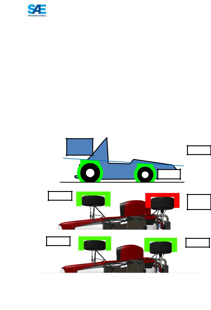
The vehicle must be open-wheeled and open-cockpit (a formula style body) with four (4) wheels that are not in a straight line.
Definition of "Open Wheel" – Open Wheel vehicles must satisfy all of the following criteria:
1)The top 180 degrees of the wheels/tires must be unobstructed when viewed 68.6mm (2.7 inches) above the plane formed by the tops of the front and rear tires.
2)The wheels/tires must be unobstructed when viewed from the side.
3)No part of the vehicle may enter a keep-out-zone defined as a circle 68.6mm (2.7 inches) larger radially than the outside diameter of the tire with the tires steered straight ahead with a 77kg (170 pound) driver seated in the normal driving position. The inner sidewall of the tire (vehicle side) is not included in this assessment. See the figure below.
Note: The dry tires will be used for all inspections. For technical inspection the keep-out-zone may be inspected by use of a tennis ball fastened to the end of a stick. The ball will have the 68.6mm (2.7 inches) diameter and must be able to be freely moved around the outside of the tire without contacting any portion of the car other than the tire.
WING
Okay
WING
Okay
Not Okay
Okay |
Okay |
|
|
24 |
© 2013 SAE International. All Rights Reserved |
2014 Formula SAE® Rules |

T2.2 Bodywork
There must be no openings through the bodywork into the driver compartment from the front of the vehicle back to the roll bar main hoop or firewall other than that required for the cockpit opening. Minimal openings around the front suspension components are allowed.
T2.3 |
Wheelbase |
|
|
|
The car must have a wheelbase of at least 1525 mm (60 inches). The wheelbase is measured from the |
||
|
center of ground contact of the front and rear tires with the wheels pointed straight ahead. |
||
T2.4 |
Vehicle Track |
|
|
|
The smaller track of the vehicle (front or rear) must be no less than 75% of the larger track. |
||
T2.5 |
Visible Access |
|
|
|
All items on the Inspection Form must be clearly visible to the technical inspectors without using |
||
|
instruments such as endoscopes or mirrors. Visible access can be provided by removing body panels |
||
|
or by providing removable access panels. |
|
|
ARTICLE 3: DRIVER’S CELL |
|
||
T3.1 |
Vehicle Structure - 2 Options |
|
|
|
Teams may, at their option, design their vehicle to comply with either of two (2) separate, but related, |
||
|
sets of requirements and restrictions. Specifically, teams may elect to comply with either: |
||
|
(1) Part T Article 3 “Drivers Cell” as defined below or |
|
|
|
(2) Part AF “Alternate Frame Rules” as found in Appendix AF and the FSAE website. |
||
T3.1.1 |
Notice Requirement – Teams planning to use the Part AF “Alternate Frame Rules” must notify the |
||
|
Rules committee of their intent by the date posted on the SAE Website. The instructions for |
||
|
notification appear in Part AF. The Rules Committee will review the submission and notify the team |
||
|
if the request is granted. Part AF has significant analytical requirements and as it is still in |
||
|
development this application process will insure that the Committee can handle the workload and give |
||
|
teams the support they may require to show certification as well as insure the teams have the technical |
||
|
capability to analyze their design and prove compliance with the AF Rules. |
||
T3.1.2 |
Alternate Frame Rules use requires the submission of the “Structural Requirements Certification Form |
||
|
(SRCF)” which supersedes the “Structural Equivalency Spreadsheet”. |
||
|
Teams submitting a Structural Requirements Certification Form (SRCF) do not have to submit a |
||
|
Structural Equivalency Spreadsheet (SES). |
|
|
T3.2 |
General Requirements |
|
|
|
Among other requirements, the vehicle’s structure must include two roll hoops that are braced, a front |
||
|
bulkhead with support system and Impact Attenuator, and side impact structures. |
||
T3.3 |
Definitions |
|
|
|
The following definitions apply throughout the Rules document: |
|
|
|
• |
Main Hoop - A roll bar located alongside or just behind the driver’s torso. |
|
|
• |
Front Hoop - A roll bar located above the driver’s legs, in proximity to the steering wheel. |
|
|
• |
Roll Hoops – Both the Front Hoop and the Main Hoop are classified as “Roll Hoops” |
|
|
|
25 |
|
© 2013 SAE International. All Rights Reserved |
2014 Formula SAE® Rules |
||

•Roll Hoop Bracing Supports – The structure from the lower end of the Roll Hoop Bracing back to the Roll Hoop(s).
•Frame Member - A minimum representative single piece of uncut, continuous tubing.
•Frame - The “Frame” is the fabricated structural assembly that supports all functional vehicle systems. This assembly may be a single welded structure, multiple welded structures or a combination of composite and welded structures.
•Primary Structure – The Primary Structure is comprised of the following Frame components: 1) Main Hoop, 2) Front Hoop, 3) Roll Hoop Braces and Supports, 4) Side Impact Structure, 5) Front Bulkhead, 6) Front Bulkhead Support System and 7) all Frame Members, guides and supports that transfer load from the Driver’s Restraint System into items 1 through 6.
•Major Structure of the Frame – The portion of the Frame that lies within the envelope defined by the Primary Structure. The upper portion of the Main Hoop and the Main Hoop Bracing are not included in defining this envelope.
•Front Bulkhead – A planar structure that defines the forward plane of the Major Structure of the Frame and functions to provide protection for the driver’s feet.
•Impact Attenuator – A deformable, energy absorbing device located forward of the Front Bulkhead.
•Side Impact Zone – The area of the side of the car extending from the top of the floor to 350 mm (13.8 inches) above the ground and from the Front Hoop back to the Main Hoop.
•Node-to-node triangulation – An arrangement of frame members projected onto a plane, where a co-planar load applied in any direction, at any node, results in only tensile or compressive forces in the frame members. This is also what is meant by “properly triangulated”.
|
|
Not OK |
Properly Triangulated |
T3.4 Minimum Material Requirements
T3.4.1 Baseline Steel Material
The Primary Structure of the car must be constructed of:
Either: Round, mild or alloy, steel tubing (minimum 0.1% carbon) of the minimum dimensions specified in the following table,
Or: Approved alternatives per Rules T3.4, T3.5, T3.6 and T3.7.
|
26 |
© 2013 SAE International. All Rights Reserved |
2014 Formula SAE® Rules |

ITEM or APPLICATION |
OUTSIDE DIMENSION |
|
X WALL THICKNESS |
Main & Front Hoops, |
Round 1.0 inch (25.4 mm) x 0.095 inch (2.4 mm) |
Shoulder Harness Mounting Bar |
or Round 25.0 mm x 2.50 mm metric |
|
|
|
|
Side Impact Structure, Front Bulkhead, |
Round 1.0 inch (25.4 mm) x 0.065 inch (1.65 mm) |
Roll Hoop Bracing, |
or Round 25.0 mm x 1.75 mm metric |
Driver’s Restraint Harness Attachment |
or Round 25.4 mm x 1.60 mm metric |
(except as noted above) |
or Square 1.00 inch x 1.00 inch x 0.049 inch |
EV: Accumulator Protection Structure |
or Square 25.0 mm x 25.0 mm x 1.25 mm metric |
|
or Square 26.0 mm x 26.0 mm x 1.2 mm metric |
Front Bulkhead Support, Main Hoop |
Round 1.0 inch (25.4 mm) x 0.049 inch (1.25 mm) |
Bracing Supports |
or Round 25.0 mm x 1.5 mm metric |
EV: Tractive System Components |
or Round 26.0 mm x 1.2 mm metric |
Note 1: The use of alloy steel does not allow the wall thickness to be thinner than that used for mild steel.
Note 2: For a specific application:
-Using tubing of the specified outside diameter but with greater wall thickness,
-Or of the specified wall thickness and a greater outside diameter,
-Or replacing round tubing with square tubing of the same or larger size to those listed above, Are NOT rules deviation requiring approval.
Note 3: Except for inspection holes, any holes drilled in any regulated tubing require the submission of an SES.
Note 4: Baseline steel properties used for calculations to be submitted in an SES may not be lower than the following:
Bending and buckling strength calculations:
Young’s Modulus (E) = 200 GPa (29,000 ksi)
Yield Strength (Sy) = 305 MPa (44.2 ksi)
Ultimate Strength (Su) = 365 MPa (52.9 ksi)
Welded monocoque attachment points or welded tube joint calculations:
Yield Strength (Sy) = 180 MPa (26ksi)
Ultimate Strength (Su) = 300 MPa (43.5 ksi)
Where welded tubing reinforcements are required (e.g. inserts for bolt holes or material to support suspension cutouts) the tubing must retain the baseline cold rolled strength while using the welded strength for the additional reinforcement material.
T3.5 Alternative Tubing and Material - General
T3.5.1 Alternative tubing geometry and/or materials may be used except that the Main Roll Hoop and Main Roll Hoop Bracing must be made from steel, i.e. the use of aluminum or titanium tubing or composites for these components is prohibited.
|
27 |
© 2013 SAE International. All Rights Reserved |
2014 Formula SAE® Rules |

T3.5.2 Titanium or magnesium on which welding has been utilized may not be used for any part of the Primary Structure. This includes the attachment of brackets to the tubing or the attachment of the tubing to other components.
T3.5.3 If a team chooses to use alternative tubing and/or materials they must submit a “Structural Equivalency Spreadsheet” per Rule T3.9. The teams must submit calculations for the material they have chosen, demonstrating equivalence to the minimum requirements found in Section T3.4.1 for yield and ultimate strengths in bending, buckling and tension, for buckling modulus and for energy dissipation. (The Buckling Modulus is defined as EI, where, E = modulus of Elasticity, and I = area moment of inertia about the weakest axis.)
T3.5.4 Tubing cannot be of thinner wall thickness than listed in T3.6 or T3.7.
T3.5.5 If a bent tube is used anywhere in the primary structure, other than the front and main roll hoops, an additional tube must be attached to support it. The attachment point must be the position along the tube where it deviates farthest from a straight line connecting both ends. The support tube must have the same diameter and thickness as the bent tube. The support tube must terminate at a node of the chassis.
T3.5.6 Any chassis design that is a hybrid of the baseline and monocoque rules, must meet all relevant rules requirements, e.g. a sandwich panel side impact structure in a tube frame chassis must meet the requirements of rules T3.28, T3.29, T3.30, T3.31 and T3.34.
Note: It is allowable for the properties of tubes and laminates to be combined to prove equivalence. E.g. in a side-impact structure consisting of one tube as per T3.4 and a laminate panel, the panel only needs to be equivalent to two side-impact tubes.
T3.6 |
Alternative Steel Tubing |
|
|
Minimum Wall Thickness Allowed: |
|
|
|
|
|
MATERIAL & APPLICATION |
MINIMUM WALL |
|
|
THICKNESS |
|
Steel Tubing for Front and Main Roll Hoops, |
|
|
and Shoulder Harness Mounting Bar |
2.0 mm (0.079 inch) |
|
Steel Tubing for Roll Hoop Bracing, Roll Hoop Bracing |
|
|
Supports, Side Impact Structure, Front Bulkhead, |
1.2 mm (0.047 inch) |
|
Front Bulkhead Support, Driver’s Harness Attachment (except as |
|
|
noted above), Protection of HV accumulators, and protection of |
|
|
HV tractive systems |
|
|
|
|
Note 1: All steel is treated equally - there is no allowance for alloy steel tubing, e.g. SAE 4130, to have a thinner wall thickness than that used with mild steel.
Note 2: To maintain EI with a thinner wall thickness than specified in T3.4.1, the outside diameter MUST be increased.
Note 3: To maintain the equivalent yield and ultimate tensile strength the same cross-sectional area of steel as the baseline tubing specified in T3.4.1 MUST be maintained.
|
28 |
© 2013 SAE International. All Rights Reserved |
2014 Formula SAE® Rules |

T3.7 Aluminum Tubing Requirements
T3.7.1 Minimum Wall Thickness: Aluminum Tubing 3.0 mm (0.118 inch)
T3.7.2 The equivalent yield strength must be considered in the “as-welded” condition, (Reference: WELDING ALUMINUM (latest Edition) by the Aluminum Association, or THE WELDING HANDBOOK, Volume 4, 7th Ed., by The American Welding Society), unless the team demonstrates and shows proof that the frame has been properly solution heat treated and artificially aged.
T3.7.3 Should aluminum tubing be solution heat-treated and age hardened to increase its strength after welding; the team must supply sufficient documentation as to how the process was performed. This includes, but is not limited to, the heat-treating facility used, the process applied, and the fixturing used.
T3.8 Composite Materials
T3.8.1 If any composite or other material is used, the team must present documentation of material type, e.g. purchase receipt, shipping document or letter of donation, and of the material properties. Details of the composite lay-up technique as well as the structural material used (cloth type, weight, and resin type, number of layers, core material, and skin material if metal) must also be submitted. The team must submit calculations demonstrating equivalence of their composite structure to one of similar geometry made to the minimum requirements found in Section T3.4.1. Equivalency calculations must be submitted for energy dissipation, yield and ultimate strengths in bending, buckling, and tension. Submit the completed “Structural Equivalency Spreadsheet” per Section T3.9.
T3.8.2 Composite materials are not allowed for the Main Hoop or the Front Hoop.
T3.9 Structural Documentation – SES or SRCF Submission
All equivalency calculations must prove equivalency relative to steel grade SAE/AISI 1010.
T3.9.1 All teams MUST submit either a STRUCTURAL EQUIVALENCY SPREADSHEET (SES) or a STRUCTURAL REQUIREMENTS CERTIFICATION FORM (SCRF).
Teams complying with the Part T Article 3 “Drivers Cell” rules MUST submit a Structural Equivalence Spreadsheet (SES), even if they are NOT planning to use alternative materials or tubing sizes to those specified in T3.4.1 Baseline Steel Materials.
Teams following the Part AF “Alternate Frame Rules” MUST submit a Structural Requirements Certification Form (SRCF). See Rule AF2.
T3.9.2 The use of alternative materials or tubing sizes to those specified in T3.4.1 “Baseline Steel Material,” is allowed, provided they have been judged by a technical review to have equal or superior properties to those specified in T3.4.1.
T3.9.3 Approval of alternative material or tubing sizes will be based upon the engineering judgment and experience of the chief technical inspector or his appointee.
T3.9.4 The technical review is initiated by completing the “Structural Equivalency Spreadsheet” (SES) using the format given in Appendix T-1.
T3.9.5 Structural Equivalency Spreadsheet – Submission
a. Address – SESs must be submitted to the officials at the competition you are entering at the address shown in the Appendix or indicated on the competition website.
|
29 |
© 2013 SAE International. All Rights Reserved |
2014 Formula SAE® Rules |
b.Due Date – SESs must be submitted no later than the date indicated on the competition website. Teams that submit their Structural Equivalency Spreadsheet after the due date for the competition will be penalized 10 points per day up to a maximum of 50 points, which will be taken off the team’s Total Score.
c.Acknowledgement – North America competitions – SESs submitted for vehicles entered into competitions held in North America will be acknowledged automatically by the fsaeonline website.
Do Not Resubmit SES’s unless instructed to do so.
T3.9.6 Vehicles completed under an approved SES must be fabricated in accordance with the materials and processes described in the SES.
T3.9.7 Teams must bring a copy of the approved SES with them to Technical Inspection.
Comment - The resubmission of an SES that was written and submitted for a competition in a previous year is strongly discouraged. Each team is expected to perform their own tests and to submit SESs based on their original work. Understanding the engineering that justifies the equivalency is essential to discussing your work with the officials.
T3.10 Main and Front Roll Hoops – General Requirements
T3.10.1 The driver’s head and hands must not contact the ground in any rollover attitude.
T3.10.2 The Frame must include both a Main Hoop and a Front Hoop as shown in Figure 1.
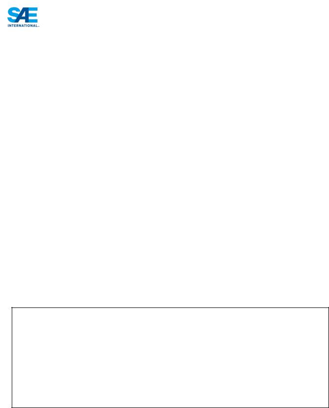
T3.10.3 When seated normally and restrained by the Driver’s Restraint System, the helmet of a 95th percentile male (anthropometrical data) and all of the team’s drivers must:
a.Be a minimum of 50.8 mm (2 inches) from the straight line drawn from the top of the main hoop to the top of the front hoop. (Figure 1a)
b.Be a minimum of 50.8 mm (2 inches) from the straight line drawn from the top of the main hoop to the lower end of the main hoop bracing if the bracing extends rearwards. (Figure 1b)
c.Be no further rearwards than the rear surface of the main hoop if the main hoop bracing extends forwards. (Figure 1c)
95th Percentile Male Template Dimensions
A two dimensional template used to represent the 95th percentile male is made to the following dimensions:
•A circle of diameter 200 mm (7.87 inch) will represent the hips and buttocks.
•A circle of diameter 200 mm (7.87 inch) will represent the shoulder/cervical region.
•A circle of diameter 300 mm (11.81 inch) will represent the head (with helmet).
•A straight line measuring 490 mm (19.29 inch) will connect the centers of the two 200 mm circles.
•A straight line measuring 280 mm (11.02 inch) will connect the centers of the upper 200 mm circle and the 300 mm head circle.
|
30 |
© 2013 SAE International. All Rights Reserved |
2014 Formula SAE® Rules |
|
31 |
© 2013 SAE International. All Rights Reserved |
2014 Formula SAE® Rules |
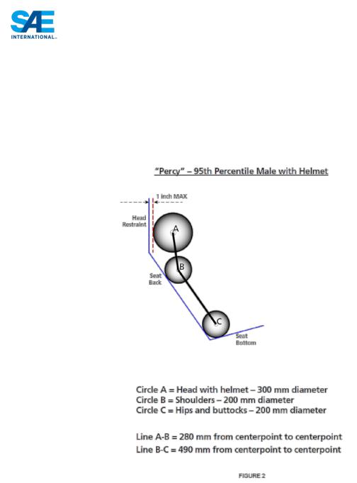
T3.10.4 The 95th percentile male template will be positioned as follows: (See Figure 2.)
•The seat will be adjusted to the rearmost position,
•The pedals will be placed in the most forward position.
•The bottom 200 mm circle will be placed on the seat bottom such that the distance between the center of this circle and the rearmost face of the pedals is no less than 915 mm (36 inches).
•The middle 200 mm circle, representing the shoulders, will be positioned on the seat back.
•The upper 300 mm circle will be positioned no more than 25.4 mm (1 inch) away from the head restraint (i.e. where the driver’s helmet would normally be located while driving).
T3.10.5 If the requirements of T3.10.4 are not met with the 95th percentile male template, the car will NOT receive a Technical Inspection Sticker and will not be allowed to compete in the dynamic events.
T3.10.6 Drivers who do not meet the helmet clearance requirements of T3.10.3 will not be allowed to drive in the competition.
T3.10.7 The minimum radius of any bend, measured at the tube centerline, must be at least three times the tube outside diameter. Bends must be smooth and continuous with no evidence of crimping or wall failure.
T3.10.8 The Main Hoop and Front Hoop must be securely integrated into the Primary Structure using gussets and/or tube triangulation.
|
32 |
© 2013 SAE International. All Rights Reserved |
2014 Formula SAE® Rules |

T3.11 Main Hoop
T3.11.1 The Main Hoop must be constructed of a single piece of uncut, continuous, closed section steel tubing per Rule T3.4.1.
T3.11.2 The use of aluminum alloys, titanium alloys or composite materials for the Main Hoop is prohibited.
T3.11.3 The Main Hoop must extend from the lowest Frame Member on one side of the Frame, up, over and down the lowest Frame Member on the other side of the Frame.
T3.11.4 In the side view of the vehicle, the portion of the Main Roll Hoop that lies above its attachment point to the Major Structure of the Frame must be within ten degrees (10°) of the vertical.
T3.11.5 In the side view of the vehicle, any bends in the Main Roll Hoop above its attachment point to the Major Structure of the Frame must be braced to a node of the Main Hoop Bracing Support structure with tubing meeting the requirements of Roll Hoop Bracing as per Rule T3.4.1.
T3.11.6 In the front view of the vehicle, the vertical members of the Main Hoop must be at least 380 mm (15 inch) apart (inside dimension) at the location where the Main Hoop is attached to the Major Structure of the Frame.
T3.12 Front Hoop
T3.12.1 The Front Hoop must be constructed of closed section metal tubing per Rule T3.4.1.
T3.12.2 The Front Hoop must extend from the lowest Frame Member on one side of the Frame, up, over and down to the lowest Frame Member on the other side of the Frame.
T3.12.3 With proper gusseting and/or triangulation, it is permissible to fabricate the Front Hoop from more than one piece of tubing.
T3.12.4 The top-most surface of the Front Hoop must be no lower than the top of the steering wheel in any angular position.
T3.12.5 The Front Hoop must be no more than 250 mms (9.8 inches) forward of the steering wheel. This distance shall be measured horizontally, on the vehicle centerline, from the rear surface of the Front Hoop to the forward most surface of the steering wheel rim with the steering in the straight-ahead position.
T3.12.6 In side view, no part of the Front Hoop can be inclined at more than twenty degrees (20°) from the vertical.
T3.13 Main Hoop Bracing
T3.13.1 Main Hoop braces must be constructed of closed section steel tubing per Rule T3.4.1.
T3.13.2 The Main Hoop must be supported by two braces extending in the forward or rearward direction on both the left and right sides of the Main Hoop.
T3.13.3 In the side view of the Frame, the Main Hoop and the Main Hoop braces must not lie on the same side of the vertical line through the top of the Main Hoop, i.e. if the Main Hoop leans forward, the braces must be forward of the Main Hoop, and if the Main Hoop leans rearward, the braces must be rearward of the Main Hoop.
|
33 |
© 2013 SAE International. All Rights Reserved |
2014 Formula SAE® Rules |

T3.13.4 The Main Hoop braces must be attached as near as possible to the top of the Main Hoop but not more than 160 mm (6.3 in) below the top-most surface of the Main Hoop. The included angle formed by the Main Hoop and the Main Hoop braces must be at least thirty degrees (30°). See Figure 3.
T3.13.5 The Main Hoop braces must be straight, i.e. without any bends.
T3.13.6 The attachment of the Main Hoop braces must be capable of transmitting all loads from the Main Hoop into the Major Structure of the Frame without failing. From the lower end of the braces there must be a properly triangulated structure back to the lowest part of the Main Hoop and the node at which the upper side impact tube meets the Main Hoop. This structure must meet the minimum requirements for Main Hoop Bracing Supports (see Rule T3.4) or an SES approved alternative. Bracing loads must not be fed solely into the engine, transmission or differential, or through suspension components.
T3.13.7 If any item which is outside the envelope of the Primary Structure is attached to the Main Hoop braces, then additional bracing must be added to prevent bending loads in the braces in any rollover attitude.
T3.14 Front Hoop Bracing
T3.14.1 Front Hoop braces must be constructed of material per Rule T3.4.1.
T3.14.2 The Front Hoop must be supported by two braces extending in the forward direction on both the left and right sides of the Front Hoop.
T3.14.3 The Front Hoop braces must be constructed such that they protect the driver’s legs and should extend to the structure in front of the driver’s feet.
T3.14.4 The Front Hoop braces must be attached as near as possible to the top of the Front Hoop but not more than 50.8 mm (2 in) below the top-most surface of the Front Hoop. See Figure 3.
T3.14.5 If the Front Hoop leans rearwards by more than ten degrees (10°) from the vertical, it must be supported by additional bracing to the rear. This bracing must be constructed of material per Rule T3.4.1.
|
34 |
© 2013 SAE International. All Rights Reserved |
2014 Formula SAE® Rules |
T3.15 Other Bracing Requirements
Where the braces are not welded to steel Frame Members, the braces must be securely attached to the Frame using 8 mm Metric Grade 8.8 (5/16 in SAE Grade 5), or stronger, bolts. Mounting plates welded to the Roll Hoop braces must be at least 2.0 mm (0.080 in) thick steel.
T3.16 Other Side Tube Requirements
If there is a Roll Hoop brace or other frame tube alongside the driver, at the height of the neck of any of the team’s drivers, a metal tube or piece of sheet metal must be firmly attached to the Frame to prevent the drivers’ shoulders from passing under the roll hoop brace or frame tube, and his/her neck contacting this brace or tube.
T3.17 Mechanically Attached Roll Hoop Bracing
T3.17.1 Roll Hoop bracing may be mechanically attached.
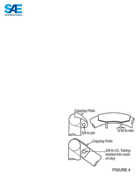
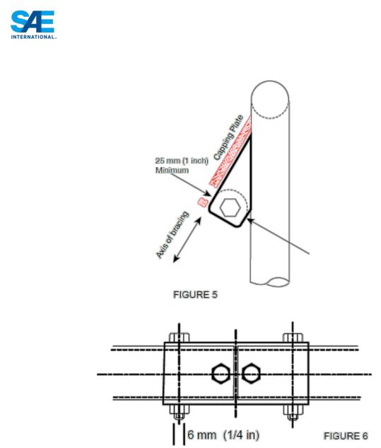
T3.17.2 Any non-permanent joint at either end must be either a double-lug joint as shown in Figures 4 and 5, or a sleeved butt joint as shown in Figure 6.
|
35 |
© 2013 SAE International. All Rights Reserved |
2014 Formula SAE® Rules |
T3.17.3 The threaded fasteners used to secure non-permanent joints are considered critical fasteners and must comply with ARTICLE 11:.
T3.17.4 No spherical rod ends are allowed.
T3.17.5 For double-lug joints, each lug must be at least 4.5 mm (0.177 in) thick steel, measure 25 mm (1.0 in) minimum perpendicular to the axis of the bracing and be as short as practical along the axis of the bracing.
T3.17.6 All double-lug joints, whether fitted at the top or bottom of the tube, must include a capping arrangement (Figures 4 & 5).
T3.17.7 In a double-lug joint the pin or bolt must be 10 mm Metric Grade 9.8 (3/8 in. SAE Grade 8) minimum. The attachment holes in the lugs and in the attached bracing must be a close fit with the pin or bolt.
T3.17.8 For sleeved butt joints (Figure 6), the sleeve must have a minimum length of 76 mm (3 inch); 38 mm (1.5 inch) either side of the joint, and be a close-fit around the base tubes. The wall thickness of the
|
36 |
© 2013 SAE International. All Rights Reserved |
2014 Formula SAE® Rules |

sleeve must be at least that of the base tubes. The bolts must be 6 mm Metric Grade 9.8 (1/4 inch SAE Grade 8) minimum. The holes in the sleeves and tubes must be a close-fit with the bolts.
T3.18 Frontal Impact Structure
T3.18.1 The driver’s feet and legs must be completely contained within the Major Structure of the Frame. While the driver’s feet are touching the pedals, in side and front views no part of the driver’s feet or legs can extend above or outside of the Major Structure of the Frame.
T3.18.2 Forward of the Front Bulkhead must be an energy-absorbing Impact Attenuator.
T3.19 Bulkhead
T3.19.1 The Front Bulkhead must be constructed of closed section tubing per Rule T3.4.1.
T3.19.2 Except as allowed by T3.19.3, The Front Bulkhead must be located forward of all non-crushable objects, e.g. batteries, master cylinders, hydraulic reservoirs.
T3.19.3 The Front Bulkhead must be located such that the soles of the driver’s feet, when touching but not applying the pedals, are rearward of the bulkhead plane. (This plane is defined by the forward-most surface of the tubing.) Adjustable pedals must be in the forward most position.
T3.20 Front Bulkhead Support
T3.20.1 The Front Bulkhead must be securely integrated into the Frame.
T3.20.2 The Front Bulkhead must be supported back to the Front Roll Hoop by a minimum of three (3) Frame Members on each side of the vehicle with one at the top (within 50.8 mm (2 inches) of its top-most surface), one (1) at the bottom, and one (1) as a diagonal brace to provide triangulation.
T3.20.3 The triangulation must be node-to-node, with triangles being formed by the Front Bulkhead, the diagonal and one of the other two required Front Bulkhead Support Frame Members.
T3.20.4 All the Frame Members of the Front Bulkhead Support system listed above must be constructed of closed section tubing per Section T3.4.1.
T3.21 Impact Attenuator
T3.21.1 The Impact Attenuator must be:
a.Installed forward of the Front Bulkhead.
b.At least 200 mm (7.8 in) long, with its length oriented along the fore/aft axis of the Frame.
c.At least 100 mm (3.9 in) high and 200 mm (7.8 in) wide for a minimum distance of 200 mm (7.8 in) forward of the Front Bulkhead.
d.Such that it cannot penetrate the Front Bulkhead in the event of an impact.
e.Attached securely and directly to the Front Bulkhead and not by being part of nonstructural bodywork.
T3.21.2 The attachment of the Impact Attenuator must be constructed to provide an adequate load path for transverse and vertical loads in the event of off-center and off-axis impacts.
T3.21.3 The attachment of the Impact Attenuator to a monocoque structure requires an approved “Structural Equivalency Spreadsheet” per Article T3.9 that shows equivalency to a minimum of four (4) 8 mm Grade 8.8 (5/16 inch Grade 5) bolts.
|
37 |
© 2013 SAE International. All Rights Reserved |
2014 Formula SAE® Rules |

T3.21.4 On all cars, a 1.5 mm (0.060 in) solid steel or 4.0 mm (0.157 in) solid aluminum “anti-intrusion plate” must be integrated into the Impact Attenuator. If the IA plate is bolted to the Front Bulkhead, it must be the same size as the outside dimensions of the Front Bulkhead. If it is welded to the Front Bulkhead, it must extend at least to the centerline of the Front Bulkhead tubing.
T3.21.5 If the anti-intrusion plate is not integral with the frame, i.e. welded, a minimum of four (4) 8 mm Metric Grade 8.8 (5/16 inch SAE Grade 5) bolts must attach the Impact Attenuator to the Front Bulkhead.
T3.21.6 Alternative designs of the anti-intrusion plate required by T3.21.4 that do not comply with the minimum specifications given above require an approved “Structural Equivalency Spreadsheet” per Article T3.9. Equivalency must also be proven for perimeter shear strength of the proposed design.
T3.22 Impact Attenuator Data Requirement
T3.22.1 The team must submit test data to show that their Impact Attenuator, when mounted on the front of a vehicle with a total mass of 300 kg (661 lbs) and run into a solid, non-yielding impact barrier with a velocity of impact of 7.0 meters/second (23.0 ft/sec), would give an average deceleration of the vehicle not to exceed 20 g’s, with a peak deceleration less than or equal to 40 g’s. Total energy absorbed must meet or exceed 7350 Joules.
Note: These are the attenuator functional requirements not test requirements. Quasi-static testing is allowed.
T3.22.2 When using acceleration data, the average deceleration must be calculated based on the raw data. The peak deceleration can be assessed based on the raw data, and if peaks above the 40g limit are apparent in the data, it can then be filtered with a Channel Filter Class (CFC) 60 (100 Hz) filter per SAE Recommended Practice J211 “Instrumentation for Impact Test”, or a 100 Hz, 3rd order, low pass Butterworth (-3dB at 100 Hz) filter.
T3.22.3 A schematic of the test method must be supplied along with photos of the attenuator before and after testing.
T3.22.4 The test piece must be presented at technical inspection for comparison to the photographs and the attenuator fitted to the vehicle.
T3.22.5 The test data and calculations must be submitted electronically in Adobe Acrobat ® format (*.pdf file) to the address and by the date provided in the Action Deadlines provided on the relevant competition website. This material must be a single file (text, drawings, data or whatever you are including).
T3.22.6 The Impact Attenuator Data must be named as follows: carnumber_schoolname_competition code_IAD.pdf using the assigned car number, the complete school name and competition code
[Example: 087_University of SAE_FSAEM_IAD.pdf]
Competition Codes are listed in Rule A.2.6
T3.22.7 Teams that submit their Impact Attenuator Data Report after the due date will be penalized 10 points per day up to a maximum of 50 points, which will be taken off the team’s Total Score.
T3.22.8 Impact Attenuator Reports will be evaluated by the organizers and the evaluations will be passed to the Design Event Captain for consideration in that event.
|
38 |
© 2013 SAE International. All Rights Reserved |
2014 Formula SAE® Rules |

T3.22.9 During the test, the attenuator must be attached to the anti-intrusion plate using the intended vehicle attachment method. The anti-intrusion plate must be spaced at least 50 mm (2 inches) from any rigid surface. No part of the anti-intrusion plate may permanently deflect more than 25.4 mm (1 inch) beyond the position of the anti-intrusion plate before the test.
Note: The 25.4 mm (1 inch) spacing represents the front bulkhead support and insures that the plate does not intrude excessively into the cockpit
T3.22.10 Dynamic testing (sled, pendulum, drop tower, etc.) of the impact attenuator may only be done at a dedicated test facility. The test facility may be part of the University but must be supervised by professional staff or University faculty. Teams are not allowed to construct their own dynamic test apparatus. Quasi-static testing may be performed by teams using their universities facilities/equipment, but teams are advised to exercise due care when performing all tests.
T3.22.11 Standard Attenuator – An officially approved impact attenuator can be found at http://www.fsaeonline.com.
Teams may choose to use that style of impact attenuator and need not submit test data with their IAD Report. The other requirements of the IAD Report must still be submitted including, but not limited to, photos of the team’s actual attenuator with evidence that it meets the design criteria given on the website.
T3.23 Non-Crushable Objects
T3.23.1 Except as allowed by T3.23.2, all non-crushable objects (e.g. batteries, master cylinders, hydraulic reservoirs) must be rearward of the bulkhead. No non-crushable objects are allowed in the impact attenuator zone.
T3.23.2 The front wing and wing supports may be forward of the Front Bulkhead, but may NOT be located in or pass through the Impact Attenuator. If the wing supports are in front of the Front Bulkhead, the supports must be included in the test of the Impact Attenuator for T3.22.
T3.24 Front Bodywork
T3.24.1 Sharp edges on the forward facing bodywork or other protruding components are prohibited.
T3.24.2 All forward facing edges on the bodywork that could impact people, e.g. the nose, must have forward facing radii of at least 38 mm (1.5 inches). This minimum radius must extend to at least forty-five degrees (45°) relative to the forward direction, along the top, sides and bottom of all affected edges.
T3.25 Side Impact Structure for Tube Frame Cars
The Side Impact Structure must meet the requirements listed below.
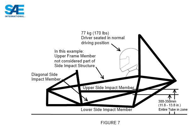
T3.25.1 The Side Impact Structure for tube frame cars must be comprised of at least three (3) tubular members located on each side of the driver while seated in the normal driving position, as shown in Figure 7.
|
39 |
© 2013 SAE International. All Rights Reserved |
2014 Formula SAE® Rules |
T3.25.2 The three (3) required tubular members must be constructed of material per Section T3.4.
T3.25.3 The locations for the three (3) required tubular members are as follows:
•The upper Side Impact Structural member must connect the Main Hoop and the Front Hoop. With a 77kg (170 pound) driver seated in the normal driving position all of the member must be at a height between 300 mm (11.8 inches) and 350 mm (13.8 inches) above the ground. The upper frame rail may be used as this member if it meets the height, diameter and thickness requirements.
•The lower Side Impact Structural member must connect the bottom of the Main Hoop and the bottom of the Front Hoop. The lower frame rail/frame member may be this member if it meets the diameter and wall thickness requirements.
•The diagonal Side Impact Structural member must connect the upper and lower Side Impact Structural members forward of the Main Hoop and rearward of the Front Hoop.
T3.25.4 With proper gusseting and/or triangulation, it is permissible to fabricate the Side Impact Structural members from more than one piece of tubing.
T3.25.5 Alternative geometry that does not comply with the minimum requirements given above requires an approved “Structural Equivalency Spreadsheet” per Rule T3.9.
T3.26 Inspection Holes
T3.26.1 The Technical Inspectors may check the compliance of all tubes. This may be done by the use of ultra-sonic testing or by the drilling of inspection holes at the inspector’s request.
T3.27 Composite Space Frames
Composite space frames are not prohibited by the rules, but any team wishing to build a composite space frame must seek approval from their organizing body. The team, at a minimum, must provide test data on the actual joints used in the frame. These tests must include static strength testing on representative configurations from all locations in the frame. An assessment of the ability of the joints to handle cyclic loading must also be assessed. This information must be included in the
|
40 |
© 2013 SAE International. All Rights Reserved |
2014 Formula SAE® Rules |
structural equivalency submission or the structural requirements certification submission, whichever approach the team is using.
Note: Given the extra complexity of a composite spaceframe and the detailed review process that will be required, teams are encouraged to submit their documents well in advance early of the deadline and to attain approval before starting their vehicle build.
T3.28 Monocoque General Requirements
All equivalency calculations must prove equivalency relative to steel grade SAE/AISI 1010.
T3.28.1 All sections of the rules apply to monocoque structures except for the following sections which supplement or supersede other rule sections.
T3.28.2 Monocoque construction requires an approved Structural Equivalency Spreadsheet, per Section T3.9. The form must demonstrate that the design is equivalent to a welded frame in terms of energy dissipation, yield and ultimate strengths in bending, buckling and tension. Information must include: material type(s), cloth weights, resin type, fiber orientation, number of layers, core material, and layup technique. The 3 point bend test and shear test data and pictures must also be included as per T3.31 Monocoque Laminate Testing. The Structural Equivalency must address each of the items below. Data from the laminate testing results must be used as the basis for any strength or stiffness calculations.
T3.28.3 Composite and metallic monocoques have the same requirements.
T3.28.4 Composite monocoques must meet the materials requirements in Rule T3.8 Composite Materials.
T3.29 Monocoque Inspections
Due to the monocoque rules and methods of manufacture it is not always possible to inspect all aspect of a monocoque during technical inspection. For items which cannot be verified by an inspector it is the responsibility of the team to provide documentation, both visual and/or written, that the requirements have been met. Generally the following items should be possible to be confirmed by the technical inspector:
•Verification of the main hoop outer diameter and thickness where it protrudes above the monocoque
•Visual verification that the main hoop goes to the lowest part of the tub, locally. This may be difficult as the tube is allowed to be integrated into the laminate but there is often a contour that comes from the tube that is visible.
•Verify mechanical attachment of main hoop to tub exists and matches the SES, at all points shown on the SES.
•Verify visually or by feel that the front roll hoop is installed. Verify mechanical attachment (if included) against the SES.
Items such as the size and composition of the front roll hoop, when integrally bonded to the monocoque, must be proven with documentation that shows dimensions on the tubes and pictures of the dimensioned tube being included in the layup. A team found to be improperly presenting any evidence of the manufacturing process will be barred from competing with a monocoque through at least the following year.
|
41 |
© 2013 SAE International. All Rights Reserved |
2014 Formula SAE® Rules |

T3.30 Monocoque Buckling Modulus – Equivalent Flat Panel Calculation
When specified in the rules, the EI of the monocoque must be calculated as the EI of a flat panel with the same composition as the monocoque about the neutral axis of the laminate. The curvature of the panel and geometric cross section of the monocoque must be ignored for these calculations.
Note: Calculations of EI that do not reference T3.30 may take into account the actual geometry of the monocoque.
T3.31 Monocoque Laminate Testing
Teams must build a representative section of the monocoque side impact zone (defined in T3.34) side as a flat panel and perform a 3 point bending test on this panel. They must prove by physical test that a section 200mm (7.9 inches) x 500 mm (19.7 inches) has at least the same properties as a baseline steel side impact tube (See T3.4.1 “Baseline Steel Materials”) for bending stiffness and two side impact tubes for yield and ultimate strength. The data from these tests and pictures of the test samples must be included in the SES, the test results will be used to derive strength and stiffness properties used in the SES formulae for all laminate panels. The test specimen must be presented at technical inspection. If the test specimen does not meet these requirements then the monocoque side impact zone must be strengthened appropriately.
Note: Teams are advised to make an equivalent test with the base line steel tubes such that any compliance in the test rig can be accounted for.
T3.31.1 If laminates with a lay-up different to that of the side-impact structure are used then additional physical tests must be completed for any part of the monocoque that forms part of the primary structure. The material properties derived from these tests must then be used in the SES for the appropriate equivalency calculations
Note: A laminate with more or less plies, of the same lay-up as the side-impact structure, does not constitute a “different lay-up” and the material properties may be scaled accordingly.
T3.31.2 Perimeter shear tests must be completed by measuring the force required to push or pull a 25mm (1”) diameter flat punch through a flat laminate sample.
The sample, measuring at least 100mm x 100mm (3.9” x 3.9”), must have core and skin thicknesses identical to those used in the actual monocoque and be manufactured using the same materials and processes.
The fixture must support the entire sample, except for a 32mm (1.25”) hole aligned co-axially with the punch. The sample must not be clamped to the fixture.
The force-displacement data and photos of the test setup must be included in the SES.
The first peak in the load-deflection curve must be used to determine the skin shear strength, this may be less than the minimum force required by T3.33.3/T3.34.3.
The maximum force recorded must meet the requirements of T3.33.3/T3.34.3.
Note: The edge of the punch and hole in the fixture may include an optional fillet up-to a maximum radius of 1mm (0.040”).
|
42 |
© 2013 SAE International. All Rights Reserved |
2014 Formula SAE® Rules |
T3.32 Monocoque Front Bulkhead
See Rule T3.28 for general requirements that apply to all aspects of the monocoque. In addition when modeled as an “L” shaped section the EI of the front bulkhead about both vertical and lateral axis must be equivalent to that of the tubes specified for the front bulkhead under T3.19. The length of the section perpendicular to the bulkhead may be a maximum of 25.4mm (1”) measured from the rearmost face of the bulkhead.
Furthermore any front bulkhead which supports the IA plate must have a perimeter shear strength equivalent to a 1.5 mm thick steel plate.
T3.33 Monocoque Front Bulkhead Support
T3.33.1 In addition to proving that the strength of the monocoque is adequate, the monocoque must have equivalent EI to the sum of the EI of the six (6) baseline steel tubes that it replaces.
T3.33.2 The EI of the vertical side of the front bulkhead support structure must be equivalent to at least the EI of one baseline steel tube that it replaces when calculated as per rule T3.30 Monocoque Buckling Modulus.
T3.33.3 The perimeter shear strength of the monocoque laminate in the front bulkhead support structure should be at least 4kN (880 pounds) for a section with a diameter of 25 mm (1 inch). This must be proven by a physical test completed as per T3.31.2 and the results include in the SES
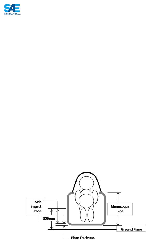
T3.34 Monocoque Side Impact
T3.34.1 In addition to proving that the strength of the monocoque is adequate, the side of the monocoque must have equivalent EI to the sum of the EI of the three (3) baseline steel tubes that it replaces.
T3.34.2 The side of the monocoque between the upper surface of the floor and 350 mm (13.8 inches) above the ground (Side Impact Zone) must have an EI of at least 50% of the sum of the EI of the three (3) baseline steel tubes that it replaces when calculated as per Rule T3.30 Monocoque Buckling Modulus.
T3.34.3 The perimeter shear strength of the monocoque laminate should be at least 7.5 kN (1700 pounds) for a section with a diameter of 25 mm (1 inch). This must be proven by physical test completed as per T3.31.2 and the results included in the SES.
T3.35 Monocoque Main Hoop
|
43 |
© 2013 SAE International. All Rights Reserved |
2014 Formula SAE® Rules |

T3.35.1 The Main Hoop must be constructed of a single piece of uncut, continuous, closed section steel tubing per T3.4.1 and extend down to the bottom of the monocoque.
T3.35.2 The Main Hoop must be mechanically attached at the top and bottom of the monocoque and at intermediate locations as needed to show equivalency.
T3.35.3 Mounting plates welded to the Roll Hoop shall be at least 2.0 mm (0.080 inch) thick steel.
T3.35.4 Attachment of the Main Hoop to the monocoque must comply with T3.40.
T3.36 Monocoque Front Hoop
T3.36.1 Composite materials are not allowed for the front hoop. See Rule T3.28 for general requirements that apply to all aspects of the monocoque.
T3.36.2 Attachment of the Front Hoop to the monocoque must comply with Rule T3.40.
T3.36.3 Fully laminating the front hoop into the monocoque is acceptable. Equivalence to at least four mounts compliant with Rule T3.40 must be shown in the SES.
Evidence as per T3.29 must be shown to pass technical inspection.
Note: The use of adhesive as the sole method of attaching the front hoop to the monocoque is not acceptable. Fully laminating means encapsulating the hoop with an appropriate number and arrangement of plies.
T3.37 Monocoque Front and Main Hoop Bracing
T3.37.1 See Rule T3.28 for general requirements that apply to all aspects of the monocoque.
T3.37.2 Attachment of tubular Front or Main Hoop Bracing to the monocoque must comply with Rule T3.40.
T3.38 Monocoque Impact Attenuator Attachment
The attachment of the Impact Attenuator to a monocoque structure requires an approved “Structural Equivalency Spreadsheet” per Rule T3.9 that shows the equivalency to a minimum of four (4) 8 mm Metric Grade 8.8 (5/16 inch SAE Grade 5) bolts.
T3.39 Monocoque Impact Attenuator Anti-intrusion Plate
See Rule T3.28 for general requirements that apply to all aspects of the monocoque and Rule T3.21.6 for alternate anti-intrusion plate designs.
T3.40 Monocoque Attachments
T3.40.1 In any direction, each attachment point between the monocoque and the other primary structure must be able to carry a load of 30kN.
T3.40.2 The laminate, mounting plates, backing plates and inserts must have sufficient shear area, weld area and strength to carry the specified 30kN load in any direction. Data obtained from the laminate perimeter shear strength test (T3.34.3) should be used to prove adequate shear area is provided
T3.40.3 Each attachment point requires a minimum of two (2) 8 mm Metric Grade 8.8 (5/16 inch SAE Grade 5) bolts
|
44 |
© 2013 SAE International. All Rights Reserved |
2014 Formula SAE® Rules |
T3.40.4 Each attachment point requires steel backing plates with a minimum thickness of 2 mm. Alternate materials may be used for backing plates if equivalency is approved.
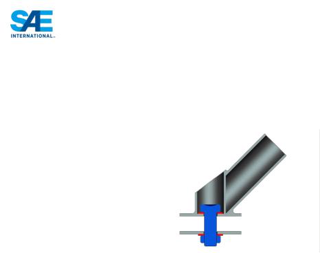
T3.40.5 The Front Hoop Bracing, Main Hoop Bracing and Main Hoop Bracing Supports only may use one (1) 10 mm Metric Grade 8.8 (3/8 inch SAE Grade 5) bolt as an alternative to T3.40.3 if the bolt is on the centerline of tube similar to the figure below.
T3.40.6 No crushing of the core is permitted
T3.40.7 Main Hoop bracing attached to a monocoque (i.e. not welded to a rear space frame) is always considered “mechanically attached” and must comply with Rule T3.17.
T3.41 Monocoque Driver’s Harness Attachment Points
T3.41.1 The monocoque attachment points for the shoulder and lap belts must support a load of 13 kN (~3000 pounds) before failure.
T3.41.2 The monocoque attachment points for the ant-submarine belts must support a load of 6.5 kN (~1500 pounds) before failure.
T3.41.3 If the lap belts and anti-submarine belts are attached to the same attachment point, then this point must support a load of 19.5 kN (~4500 pounds) before failure.
T3.41.4 The strength of lap belt attachment and shoulder belt attachment must be proven by physical test where the required load is applied to a representative attachment point where the proposed layup and attachment bracket is used.
ARTICLE 4: COCKPIT
T4.1 Cockpit Opening
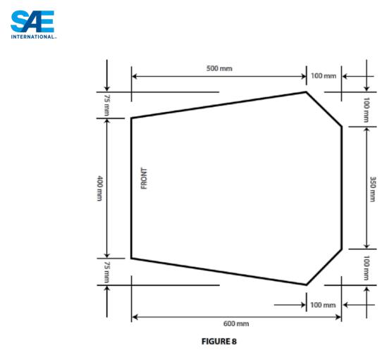
T4.1.1 In order to ensure that the opening giving access to the cockpit is of adequate size, a template shown in Figure 8 will be inserted into the cockpit opening. It will be held horizontally and inserted vertically until it has passed below the top bar of the Side Impact Structure (or until it is 350 mm (13.8 inches) above the ground for monocoque cars). No fore and aft translation of the template will be permitted during insertion.
|
45 |
© 2013 SAE International. All Rights Reserved |
2014 Formula SAE® Rules |
T4.1.2 During this test, the steering wheel, steering column, seat and all padding may be removed. The shifter or shift mechanism may not be removed unless it is integral with the steering wheel and is removed with the steering wheel. The firewall may not be moved or removed.
Note: As a practical matter, for the checks, the steering column will not be removed. The technical inspectors will maneuver the template around the steering column shaft, but not the steering column supports.
T4.2 Cockpit Internal Cross Section:
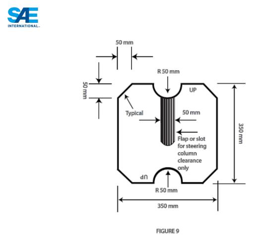
T4.2.1 A free vertical cross section, which allows the template shown in Figure 9 to be passed horizontally through the cockpit to a point 100 mm (4 inches) rearwards of the face of the rearmost pedal when in the inoperative position, must be maintained over its entire length. If the pedals are adjustable, they will be put in their most forward position.
|
46 |
© 2013 SAE International. All Rights Reserved |
2014 Formula SAE® Rules |
T4.2.2 The template, with maximum thickness of 7mm (0.275 inch), will be held vertically and inserted into the cockpit opening rearward of the Front Roll Hoop, as close to the Front Roll Hoop as the car’s design will allow.
T4.2.3 The only items that may be removed for this test are the steering wheel, and any padding required by Rule T5.8 “Driver’s Leg Protection” that can be easily removed without the use of tools with the driver in the seat. The seat may NOT be removed.
T4.2.4 Teams whose cars do not comply with T4.1.1 or T4.2.1will not be given a Technical Inspection Sticker and will NOT be allowed to compete in the dynamic events.
Note: Cables, wires, hoses, tubes, etc. must not impede the passage of the templates required by T4.1.1 and T4.2.
T4.3 Driver’s Seat
T4.3.1 The lowest point of the driver’s seat must be no lower than the bottom surface of the lower frame rails or by having a longitudinal tube (or tubes) that meets the requirements for Side Impact tubing, passing underneath the lowest point of the seat.
T4.3.2 When seated in the normal driving position, adequate heat insulation must be provided to ensure that the driver will not contact any metal or other materials which may become heated to a surface temperature above sixty degrees C (60°C). The insulation may be external to the cockpit or incorporated with the driver’s seat or firewall. The design must show evidence of addressing all three
(3) types of heat transfer, namely conduction, convection and radiation, with the following between the heat source, e.g. an exhaust pipe or coolant hose/tube and the panel that the driver could contact, e.g. the seat or floor:
|
47 |
© 2013 SAE International. All Rights Reserved |
2014 Formula SAE® Rules |

a.Conduction Isolation by:
i.No direct contact between the heat source and the panel, or
ii.A heat resistant, conduction isolation material with a minimum thickness of 8 mm (0.3 in) between the heat source and the panel.
b.Convection Isolation by a minimum air gap of 25 mm (1 inch) between the heat source and the panel
c.Radiation Isolation by:
i. A solid metal heat shield with a minimum thickness of 0.4 mm (0.015 in) or
ii.Reflective foil or tape when combined with a.ii above.
T4.4 Floor Close-out
All vehicles must have a floor closeout made of one or more panels, which separate the driver from the pavement. If multiple panels are used, gaps between panels are not to exceed 3 mm (1/8 inch). The closeout must extend from the foot area to the firewall and prevent track debris from entering the car. The panels must be made of a solid, non-brittle material.
T4.5 Firewall
T4.5.1 A firewall must separate the driver compartment from all components of the fuel supply, the engine oil, the liquid cooling systems and any high voltage system (PART EV - EV1.1). It must protect the neck of the tallest driver. It must extend sufficiently far upwards and/or rearwards such that any point less than 100 mm (4 ins.) above the bottom of the helmet of the tallest driver shall not be in direct line of sight with any part of the fuel system, the cooling system or the engine oil system.
T4.5.2 The firewall must be a non-permeable surface made from a rigid, fire resistant material and for electric vehicles must also comply with PART EV - EV4.3.
T4.5.3 Any firewall must seal completely against the passage of fluids, especially at the sides and the floor of the cockpit, i.e. there can be no holes in a firewall through which seat belts pass.
T4.5.4 Pass-throughs for wiring, cables, etc. are allowable if grommets are used to seal the pass-throughs. Also, multiple panels may be used to form the firewall but must be sealed at the joints.
T4.6 Accessibility of Controls
All vehicle controls, including the shifter, must be operated from inside the cockpit without any part of the driver, e.g. hands, arms or elbows, being outside the planes of the Side Impact Structure defined in Rule T3.25 and T3.34.
T4.7 |
Driver Visibility |
|
T4.7.1 |
General Requirement |
|
|
The driver must have adequate visibility to the front and sides of the car. With the driver seated in a |
|
|
normal driving position he/she must have a minimum field of vision of two hundred degrees (200°) (a |
|
|
minimum one hundred degrees (100°) to either side of the driver). The required visibility may be |
|
|
obtained by the driver turning his/her head and/or the use of mirrors. |
|
T4.7.2 |
Mirrors |
|
|
If mirrors are required to meet Rule T4.7.1, they must remain in place and adjusted to enable the |
|
|
required visibility throughout all dynamic events. |
|
T4.8 |
Driver Egress |
|
|
48 |
|
© 2013 SAE International. All Rights Reserved |
2014 Formula SAE® Rules |
|

All drivers must be able to exit to the side of the vehicle in no more than 5 seconds. Egress time begins with the driver in the fully seated position, hands in driving position on the connected steering wheel and wearing the required driver equipment. Egress time will stop when the driver has both feet on the pavement.
ARTICLE 5: DRIVERS EQUIPMENT (BELTS AND COCKPIT PADDING)
T5.1 Belts - General
T5.1.1 Definitions
a.A 5-point system – consists of a 76 mm (3 inch) wide lap belt, approximately 76 mm (3 inch) wide shoulder straps and a single approximately 51 mm (2 inch) wide anti-submarine strap. The single anti-submarine strap must have a metal-to-metal connection with the single release common to the lap belt and shoulder harness.
b.A 6-point system – consists of a 76 mm (3 inch) wide lap belt, approximately 76 mm (3 inch) wide shoulder straps and two (2) approximately 51 mm (2 inch) wide leg or anti-submarine straps.
c.A 7-point system – system is the same as the 6-point except it has three (3) anti-submarine straps, two (2) from the 6-point system and one (1) from the 5-point system.
Note: 6 and 7-point harnesses to FIA specification 8853/98 and SFI Specification 16.5 with approximately 51 mm (2 inch) lap belts are acceptable.
d.An “upright driving position” is defined as one with a seat back angled at thirty degrees (30°) or
less from the vertical as measured along the line joining the two 200 mm circles of the template of the 95th percentile male as defined in Rule T3.10.3 and positioned per T3.10.4.
e.A “reclined driving position” is defined as one with a seat back angled at more than thirty degrees
(30°) from the vertical as measured along the line joining the two 200 mm circles of the template of the 95th percentile male as defined in Rule T3.10.3 and positioned per T3.10.4.
f.The “chest-groin line” is the straight line that in side view follows the line of the shoulder belts from the chest to the release buckle.
T5.1.2 Harness Requirements
All drivers must use a 5, 6 or 7 point restraint harness meeting the following specifications:
a.All driver restraint systems must meet SFI Specification 16.1, SFI Specification 16.5, or FIA specification 8853/98.
b.The belts must bear the appropriate dated labels.
c.The material of all straps must be in perfect condition.
d.There must be a single release common to the lap belt and shoulder harness using a metal-to-metal quick release type latch.
e.To accommodate drivers of differing builds, all lap belts must have a “quick adjuster” feature. Lap belts with “pull-up” adjusters are recommended over “pull-down” adjusters.
f.Cars with a “reclined driving position” (see 5.1.1.e above) must have either a 6 point or 7-point harness, AND have either anti-submarine belts with “quick adjusters” or have two (2) sets of antisubmarine belts installed.
g.The shoulder harness must be the over-the-shoulder type. Only separate shoulder straps are permitted (i.e. “y”-type shoulder straps are not allowed). The “H”-type configuration is allowed.
h.It is mandatory that the shoulder harness, where it passes over the shoulders, be 76 mm (3 inch) wide, except as noted below. The shoulder harness straps must be threaded through the three bar adjusters in accordance with manufacturer’s instructions.
i.When the HANS device is used by the driver, FIA certified 51 mm (2 inch) wide shoulder harnesses are allowed. Should a driver, at any time not utilize the HANS device, then 76 mm (3 inch) wide shoulder harnesses are required.
|
49 |
© 2013 SAE International. All Rights Reserved |
2014 Formula SAE® Rules |

T5.1.3 Harness Replacement
SFI spec harnesses must be replaced following December 31st of the 2nd year after the date of manufacture as indicated by the label. FIA spec harnesses must be replaced following December 31st of the year marked on the label. (Note: FIA belts are normally certified for five (5) years from the date of manufacture.)
T5.1.4 The restraint system must be worn tightly at all times.
T5.2 Belt, Strap and Harness Installation - General
T5.2.1 The lap belt, shoulder harness and anti-submarine strap(s) must be securely mounted to the Primary Structure. Such structure and any guide or support for the belts must meet the minimum requirements of T3.4.1.
Note: Rule T3.5.5 applies to these tubes as well so a non-straight shoulder harness bar would require support per T3.5.5
T5.2.2 The tab to which any harness is attached must have:
a.A minimum cross sectional area of 40 sq. mm (0.062 sq. in) of steel to be sheared or failed in tension at any point of the tab, and
b.A minimum thickness of 1.6 mm (0.063 inch).
c.Where lap belts and anti-submarine belts use the same attachment point, a minimum cross sectional area of 90 sq. mm (0.140 sq in) of steel to be sheared if failed in tension at any point of the tab.
|
Note: Double shear mounting is preferred. |
T5.2.3 |
Harnesses, belts and straps must not pass through a firewall, i.e. all harness attachment points must |
|
be on the driver’s side of any firewall. |
T5.2.4 |
The attachment of the Driver’s Restraint System to a monocoque structure requires an approved |
|
Structural Equivalency Spreadsheet per Rule T3.9. |
T5.2.5 |
The restraint system installation is subject to approval of the Chief Technical Inspector. |
T5.3 |
Lap Belt Mounting |
T5.3.1 |
The lap belt must pass around the pelvic area below the Anterior Superior Iliac Spines (the hip bones). |
T5.3.2 |
The lap belts should not be routed over the sides of the seat. The lap belts should come through the |
|
seat at the bottom of the sides of the seat to maximize the wrap of the pelvic surface and continue in a |
|
straight line to the anchorage point. |
T5.3.3 |
Where the belts or harness pass through a hole in the seat, the seat must be rolled or grommeted to |
|
prevent chafing of the belts. |
T5.3.4 |
To fit drivers of differing statures correctly, in side view, the lap belt must be capable of pivoting |
|
freely by using either a shouldered bolt or an eye bolt attachment, i.e. mounting lap belts by wrapping |
|
them around frame tubes is no longer acceptable. |
T5.3.5 |
With an “upright driving position”, in side view the lap belt must be at an angle of between forty-five |
|
degrees (45°) and sixty-five degrees (65°) to the horizontal. This means that the centerline of the lap |
|
50 |
© 2013 SAE International. All Rights Reserved |
2014 Formula SAE® Rules |
belt at the seat bottom should be between 0 – 76 mm (0 – 3 inches) forward of the seat back to seat bottom junction. (See Figure 10)
T5.3.6 With a “reclined driving position”, in side view the lap belt must be between an angle of sixty degrees (60°) and eighty degrees (80°) to the horizontal.
T5.4 Shoulder Harness
T5.4.1 The shoulder harness must be mounted behind the driver to structure that meets the requirements of T3.4.1. However, it cannot be mounted to the Main Roll Hoop Bracing or attendant structure without additional bracing to prevent loads being transferred into the Main Hoop Bracing.
T5.4.2 If the harness is mounted to a tube that is not straight, the joints between this tube and the structure to which it is mounted must be reinforced in side view by gussets or triangulation tubes to prevent torsional rotation of the harness mounting tube.
T5.4.3 The shoulder harness mounting points must be between 178 mm (7 inches) and 229 mm (9 inches) apart. (See Figure 11)
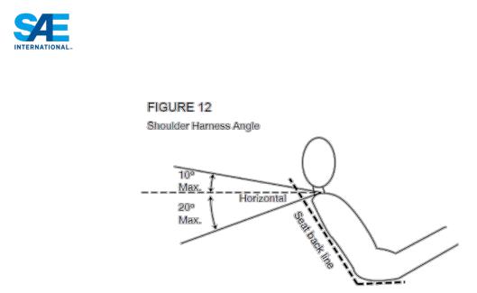
T5.4.4 From the driver’s shoulders rearwards to the mounting point or structural guide, the shoulder harness must be between ten degrees (10°) above the horizontal and twenty degrees (20°) below the horizontal. (See Figure 12).
|
51 |
© 2013 SAE International. All Rights Reserved |
2014 Formula SAE® Rules |
T5.5 Anti-Submarine Belt Mounting
T5.5.1 The anti-submarine belt of a 5 point harness should be mounted in line with, or angled slightly forward (up to twenty degrees (20°)) of, the driver’s chest-groin line.
T5.5.2 The anti-submarine belts of a 6 point harness should be mounted either:
a.With the belts going vertically down from the groin, or angled up to twenty degrees (20°) rearwards. The anchorage points should be approximately 100 mm (4 inches) apart. Or
b.With the anchorage points on the Primary Structure at or near the lap belt anchorages, the driver sitting on the anti-submarine belts, and the belts coming up around the groin to the release buckle.
T5.6 Head Restraint
T5.6.1 A head restraint must be provided on the car to limit the rearward motion of the driver’s head.
T5.6.2 The restraint must:
•Be vertical or near vertical in side view.
•Be padded with an energy absorbing material such as Ethafoam® or Ensolite® with a minimum thickness of 38 mm (1.5 inches).
•Have a minimum width of 15 cms (6 ins).
•Have a minimum area of 235 sq. cms (36 sq. ins) AND have a minimum height adjustment of
17.5cms (7 inches), OR have a minimum height of 28 cms (11 inches).
•Be located so that for each driver:
- The restraint is no more than 25 mm (1 inch) away from the back of the driver’s helmet, with the driver in their normal driving position.
- The contact point of the back of the driver’s helmet on the head restraint is no less than 50 mm (2 inch) from any edge of the head restraint.
Note: (1): Head restraints may be changed to accommodate different drivers (See T1.2.2). Note: (2): The above requirements must be met for all drivers.
Note: (3): Approximately 100mm (4”) longitudinal adjustment is required to accommodate 5th to 95th Percentile drivers. This is not a specific rules requirement, but teams must have sufficient longitudinal adjustment and/or alternative thickness head restraints available, such that the above requirements are met by all their drivers.
|
52 |
© 2013 SAE International. All Rights Reserved |
2014 Formula SAE® Rules |

T5.6.3 The restraint, its attachment and mounting must be strong enough to withstand a force of 890 Newtons (200 lbs. force) applied in a rearward direction.
T5.7 Roll Bar Padding
Any portion of the roll bar, roll bar bracing or frame which might be contacted by the driver’s helmet must be covered with a minimum thickness of 12 mm (0.5 inch) of padding which meets SFI spec 45.1 or FIA 8857-2001.
T5.8 Driver’s Leg Protection
T5.8.1 To keep the driver’s legs away from moving or sharp components, all moving suspension and steering components, and other sharp edges inside the cockpit between the front roll hoop and a vertical plane 100 mm (4 inches) rearward of the pedals, must be shielded with a shield made of a solid material.
Moving components include, but are not limited to springs, shock absorbers, rocker arms, antiroll/sway bars, steering racks and steering column CV joints.
T5.8.2 Covers over suspension and steering components must be removable to allow inspection of the mounting points.
ARTICLE 6: GENERAL CHASSIS RULES
T6.1 Suspension
T6.1.1 The car must be equipped with a fully operational suspension system with shock absorbers, front and rear, with usable wheel travel of at least 50.8 mm (2 inches), 25.4 mm (1 inch) jounce and 25.4 mm (1 inch) rebound, with driver seated. The judges reserve the right to disqualify cars which do not represent a serious attempt at an operational suspension system or which demonstrate handling inappropriate for an autocross circuit.
T6.1.2 All suspension mounting points must be visible at Technical Inspection, either by direct view or by removing any covers.
T6.2 Ground Clearance
Ground clearance must be sufficient to prevent any portion of the car, other than the tires, from touching the ground during track events. Intentional or excessive ground contact of any portion of the car other than the tires will forfeit a run or an entire dynamic event.
Comment: The intention of this rule is that sliding skirts or other devices that by design, fabrication or as a consequence of moving, contact the track surface are prohibited and any unintended contact with the ground which either causes damage, or in the opinion of the ‘dynamic event organizers’ could result in damage to the track, will result in forfeit of a run or an entire dynamic event
T6.3 Wheels
T6.3.1 The wheels of the car must be 203.2 mm (8.0 inches) or more in diameter.
T6.3.2 Any wheel mounting system that uses a single retaining nut must incorporate a device to retain the nut and the wheel in the event that the nut loosens. A second nut (“jam nut”) does not meet these requirements.
T6.3.3 Standard wheel lug bolts are considered engineering fasteners and any modification will be subject to extra scrutiny during technical inspection. Teams using modified lug bolts or custom designs will be required to provide proof that good engineering practices have been followed in their design.
|
53 |
© 2013 SAE International. All Rights Reserved |
2014 Formula SAE® Rules |

T6.3.4 Aluminum wheel nuts may be used, but they must be hard anodized and in pristine condition.
T6.4 Tires
T6.4.1 Vehicles may have two types of tires as follows:
•Dry Tires – The tires on the vehicle when it is presented for technical inspection are defined as its “Dry Tires”. The dry tires may be any size or type. They may be slicks or treaded.
•Rain Tires – Rain tires may be any size or type of treaded or grooved tire provided:
1.The tread pattern or grooves were molded in by the tire manufacturer, or were cut by the tire manufacturer or his appointed agent. Any grooves that have been cut must have documentary proof that it was done in accordance with these rules.
2.There is a minimum tread depth of 2.4 mms (3/32 inch).
Note: Hand cutting, grooving or modification of the tires by the teams is specifically prohibited.
T6.4.2 Within each tire set, the tire compound or size, or wheel type or size may not be changed after static judging has begun. Tire warmers are not allowed. No traction enhancers may be applied to the tires after the static judging has begun.
T6.5 Steering
T6.5.1 The steering wheel must be mechanically connected to the wheels, i.e. “steer-by-wire” is prohibited or electrically actuated steering, is prohibited.
T6.5.2 The steering system must have positive steering stops that prevent the steering linkages from locking up (the inversion of a four-bar linkage at one of the pivots). The stops may be placed on the uprights or on the rack and must prevent the tires from contacting suspension, body, or frame members during the track events.
T6.5.3 Allowable steering system free play is limited to seven degrees (7°) total measured at the steering wheel.
T6.5.4 The steering wheel must be attached to the column with a quick disconnect. The driver must be able to operate the quick disconnect while in the normal driving position with gloves on.
T6.5.5 The steering wheel must have a continuous perimeter that is near circular or near oval, i.e. the outer perimeter profile can have some straight sections, but no concave sections. “H”, “Figure 8”, or cutout wheels are not allowed.
T6.5.6 In any angular position, the top of the steering wheel must be no higher than the top-most surface of the Front Hoop. See Figure 3.
T6.5.7 Steering systems using cables for actuation are not prohibited by T6.5.1 but additional documentation must be submitted. The team must submit a failure modes and effects analysis report with design details of the proposed system as part of the structural equivalency spreadsheet (SES) or structural requirements certification form (SRCF). The report must outline the analysis that was done to show the steering system will function properly, potential failure modes and the effects of each failure mode and finally failure mitigation strategies used by the team. The organizing committee will review the submission and advise the team if the design is approved. If not approved, a non-cable based steering system must be used instead.
|
54 |
© 2013 SAE International. All Rights Reserved |
2014 Formula SAE® Rules |

T6.6 Jacking Point
T6.6.1 A jacking point, which is capable of supporting the car’s weight and of engaging the organizers’ “quick jacks”, must be provided at the rear of the car.
T6.6.2 The jacking point is required to be:
•Visible to a person standing 1 meter (3 feet) behind the car.
•Painted orange.
•Oriented horizontally and perpendicular to the centerline of the car
•Made from round, 25 – 29 mm (1 – 1 1/8 inch) O.D. aluminum or steel tube
•A minimum of 300 mm (12 inches) long
•Exposed around the lower 180 degrees (180°) of its circumference over a minimum length of 280 mm (11 in)
•The height of the tube is required to be such that:
-There is a minimum of 75 mm (3 in) clearance from the bottom of the tube to the ground measured at tech inspection.
-With the bottom of the tube 200 mm (7.9 in) above ground, the wheels do not touch the ground when they are in full rebound.
•Access from the rear of the tube must be unobstructed for at least 300mm of its length
Comment on Disabled Cars – The organizers and the Rules Committee remind teams that cars disabled on course must be removed as quickly as possible. A variety of tools may be used to move disabled cars including quick jacks, dollies of different types, tow ropes and occasionally even boards. We expect cars to be strong enough to be easily moved without damage. Speed is important in clearing the course and although the course crew exercises due care, parts of a vehicle can be damaged during removal. The organizers are not responsible for damage that occurs when moving disabled vehicles. Removal/recovery workers will jack, lift, carry or tow the car at whatever points they find easiest to access. Accordingly, we advise teams to consider the strength and location of all obvious jacking, lifting and towing points during the design process.
T6.7 Rollover Stability
T6.7.1 The track and center of gravity of the car must combine to provide adequate rollover stability.
T6.7.2 Rollover stability will be evaluated on a tilt table using a pass/fail test. The vehicle must not roll when tilted at an angle of sixty degrees (60°) to the horizontal in either direction, corresponding to 1.7 G’s. The tilt test will be conducted with the tallest driver in the normal driving position.
ARTICLE 7: BRAKE SYSTEM
T7.1 Brake System - General
The car must be equipped with a braking system that acts on all four wheels and is operated by a single control.
T7.1.1 It must have two (2) independent hydraulic circuits such that in the case of a leak or failure at any point in the system, effective braking power is maintained on at least two (2) wheels. Each hydraulic circuit must have its own fluid reserve, either by the use of separate reservoirs or by the use of a dammed, OEM-style reservoir.
T7.1.2 A single brake acting on a limited-slip differential is acceptable.
T7.1.3 The brake system must be capable of locking all four (4) wheels during the test specified below.
|
55 |
© 2013 SAE International. All Rights Reserved |
2014 Formula SAE® Rules |

T7.1.4 “Brake-by-wire” systems are prohibited.
T7.1.5 Unarmored plastic brake lines are prohibited.
T7.1.6 The braking systems must be protected with scatter shields from failure of the drive train (see T8.4) or from minor collisions.
T7.1.7 In side view no portion of the brake system that is mounted on the sprung part of the car can project below the lower surface of the frame or the monocoque, whichever is applicable.
T7.1.8 The brake pedal shall be designed to withstand a force of 2000 N without any failure of the brake system or pedal box. This may be tested by pressing the pedal with the maximum force that can be exerted by any official when seated normally.
T7.1.9 The brake pedal must be fabricated from steel or aluminum or machined from steel, aluminum or titanium.
T7.1.10 EV ONLY: The first 90% of the brake pedal travel may be used to regenerate brake energy without actuating the hydraulic brake system.
The remaining brake pedal travel must directly actuate the hydraulic brake system, but brake energy regeneration may remain active.
Any strategy to regenerate energy whilst coasting or whilst braking must be covered by the FMEA
T7.2 Brake Test
T7.2.1 The brake system will be dynamically tested and must demonstrate the capability of locking all four
(4) wheels and stopping the vehicle in a straight line at the end of an acceleration run specified by the brake inspectors.
T7.2.2 EV ONLY: After accelerating the tractive system has to be switched off by the driver and the driver has to lock all four wheels of the vehicle by braking. The brake test is passed if all four wheels simultaneously lock while the tractive system is shut down.
NOTE: It is acceptable if the Tractive System Active Light switches off shortly after the vehicle has come to a complete stop as the reduction of the system voltage may take up to 5 seconds.
T7.3 Brake Over-Travel Switch
T7.3.1 A brake pedal over-travel switch must be installed on the car as part of the shutdown system and wired in series with the shutdown buttons. This switch must be installed so that in the event of brake system failure such that the brake pedal over travels it will result in the shutdown system being activated and controlling the systems as defined in Part IC Article 4 (IC vehicles) or EV5.4 (electric vehicles).
T7.3.2 Repeated actuation of the switch must not restore power to these components, and it must be designed so that the driver cannot reset it.
T7.3.3 The switch must be implemented with analog components, and not through recourse to programmable logic controllers, engine control units, or similar functioning digital controllers.
T7.3.4 The Brake Over-Travel switch must be a mechanical single pole, single throw (commonly known as a two-position) switch (push-pull or flip type) as shown below.
|
56 |
© 2013 SAE International. All Rights Reserved |
2014 Formula SAE® Rules |
T7.4 Brake Light
T7.4.1 The car must be equipped with a red brake light. The brake light itself has to have a black background and a rectangular, triangular or near round shape with a minimum shining surface of at least 15cm². Each brake light must be clearly visible from the rear in very bright sunlight.
T7.4.2 This light must be mounted between the wheel centerline and driver’s shoulder level vertically and approximately on vehicle centerline laterally.
ARTICLE 8: POWERTRAIN
T8.1 Coolant Fluid Limitations
Water-cooled engines must only use plain water. Electric motors, accumulators or HV electronics can use plain water or oil as the coolant. Glycol-based antifreeze, “water wetter”, water pump lubricants of any kind, or any other additives are strictly prohibited.
T8.2 System Sealing
T8.2.1 Any cooling or lubrication system must be sealed to prevent leakage.
T8.2.2 Separate catch cans must be employed to retain fluids from any vents for the coolant system or lubrication system. Each catch-can must have a minimum volume of ten (10) percent of the fluid being contained or 0.9 liter (one U.S. quart) whichever is greater.
T8.2.3 Catch cans must be capable of containing boiling water without deformation, and be located rearwards of the firewall below driver’s shoulder level, and be positively retained, i.e. no tie-wraps or tape.
T8.2.4 Any catch can on the cooling system must vent through a hose with a minimum internal diameter of 3 mm (1/8 inch) down to the bottom levels of the Frame.
T8.3 Transmission and Drive
Any transmission and drivetrain may be used.
T8.4 Drive Train Shields and Guards
T8.4.1 Exposed high-speed final drivetrain equipment such as Continuously Variable Transmissions (CVTs), sprockets, gears, pulleys, torque converters, clutches, belt drives, clutch drives and electric motors, must be fitted with scatter shields in case of failure. The final drivetrain shield must cover the chain or belt from the drive sprocket to the driven sprocket/chain wheel/belt or pulley. The final drivetrain
|
57 |
© 2013 SAE International. All Rights Reserved |
2014 Formula SAE® Rules |

shield must start and end parallel to the lowest point of the chain wheel/belt/pulley. (See figure below) Body panels or other existing covers are not acceptable unless constructed from approved materials per T8.4.3 or T8.4.4.
Note: If equipped, the engine drive sprocket cover may be used as part of the scatter shield system.
Comment: Scatter shields are intended to contain drivetrain parts which might separate from the car.
T8.4.2 Perforated material may not be used for the construction of scatter shields.
T8.4.3 Chain Drive - Scatter shields for chains must be made of at least 2.66 mm (0.105 inch) steel (no alternatives are allowed), and have a minimum width equal to three (3) times the width of the chain. The guard must be centered on the center line of the chain and remain aligned with the chain under all conditions.
T8.4.4 Non-metallic Belt Drive - Scatter shields for belts must be made from at least 3.0 mm (0.120 inch) Aluminum Alloy 6061-T6, and have a minimum width that is equal to 1.7 times the width of the belt. The guard must be centered on the center line of the belt and remain aligned with the belt under all conditions.
T8.4.5 Attachment Fasteners - All fasteners attaching scatter shields and guards must be a minimum 6mm Metric Grade 8.8 (1/4 inch SAE Grade 5) or stronger.
T8.4.6 Finger Guards – Finger guards are required to cover any drivetrain parts that spin while the car is stationary with the engine running. Finger guards may be made of lighter material, sufficient to resist finger forces. Mesh or perforated material may be used but must prevent the passage of a 12 mm (1/2 inch) diameter object through the guard.
Comment: Finger guards are intended to prevent finger intrusion into rotating equipment while the vehicle is at rest.
|
58 |
© 2013 SAE International. All Rights Reserved |
2014 Formula SAE® Rules |

T8.5 Integrity of systems carrying fluids – Tilt Test
T8.5.1 Tilt Test - Fluids
During technical inspection, the car must be capable of being tilted to a forty-five degree (45°) angle without leaking fluid of any type.
T8.5.2 The tilt test will be conducted with the vehicle containing the maximum amount of fluids it will carry during any test or event.
ARTICLE 9: AERODYNAMIC DEVICES
T9.1 Aero Dynamics and Ground Effects - General
All aerodynamic devices must satisfy the following requirements:
T9.2 Location
T9.2.1 In plain view, no part of any aerodynamic device, wing, under tray or splitter can be:
a.Further forward than 762 mm (30 inches) forward of the fronts of the front tires
b.No further rearward than 305 mm (12 inches) rearward of the rear of the rear tires.
c.No wider than the outside of the front tires or rear tires measured at the height of the hubs, whichever is wider.
T9.3 Minimum Radii of Edges of Aerodynamic Devices
T9.3.1 All wing edges including wings, end plates, Gurney flaps, wicker bills and undertrays that could contact a pedestrian must have a minimum radius of 1.5 mm (0.060 inch).
T9.4 Ground Effect Devices
No power device may be used to move or remove air from under the vehicle except fans designed exclusively for cooling. Power ground effects are prohibited.
T9.5 Driver Egress Requirements
T9.5.1 Egress from the vehicle within the time set in Rule T4.8 “Driver Egress,” must not require any movement of the wing or wings or their mountings.
T9.5.2 The wing or wings must be mounted in such positions, and sturdily enough, that any accident is unlikely to deform the wings or their mountings in such a way to block the driver’s egress.
ARTICLE 10: COMPRESSED GAS SYSTEMS AND HIGH PRESSURE HYDRAULICS
T10.1 Compressed Gas Cylinders and Lines
Any system on the vehicle that uses a compressed gas as an actuating medium must comply with the following requirements:
a.Working Gas-The working gas must be nonflammable, e.g. air, nitrogen, carbon dioxide.
b.Cylinder CertificationThe gas cylinder/tank must be of proprietary manufacture, designed and built for the pressure being used, certified by an accredited testing laboratory in the country of its origin, and labeled or stamped appropriately.
c.Pressure Regulation-The pressure regulator must be mounted directly onto the gas cylinder/tank.
d.Protection – The gas cylinder/tank and lines must be protected from rollover, collision from any direction, or damage resulting from the failure of rotating equipment.
e.Cylinder LocationThe gas cylinder/tank and the pressure regulator must be located either rearward of the Main Roll Hoop and within the envelope defined by the Main Roll Hoop and the
|
59 |
© 2013 SAE International. All Rights Reserved |
2014 Formula SAE® Rules |

Frame (see T3.3), or in a structural side-pod. In either case it must be protected by structure that meets the requirements of T3.25 or T3.34. It must not be located in the cockpit.
f.Cylinder MountingThe gas cylinder/tank must be securely mounted to the Frame, engine or transmission.
g.Cylinder AxisThe axis of the gas cylinder/tank must not point at the driver.
h.InsulationThe gas cylinder/tank must be insulated from any heat sources, e.g. the exhaust system.
i.Lines and FittingsThe gas lines and fittings must be appropriate for the maximum possible operating pressure of the system.
T10.2 High Pressure Hydraulic Pumps and Lines
The driver and anyone standing outside the car must be shielded from any hydraulic pumps and lines with line pressures of 2100 kPa (300 psi) or higher. The shields must be steel or aluminum with a minimum thickness of 1 mm (0.039 inch).
Note: Brake lines are not classified as “hydraulic pump lines” and as such brake lines are excluded from T10.2.
ARTICLE 11: FASTENERS
T11.1 Fastener Grade Requirements
T11.1.1 All threaded fasteners utilized in the driver’s cell structure, and the steering, braking, driver’s harness and suspension systems must meet or exceed, SAE Grade 5, Metric Grade 8.8 and/or AN/MS specifications.
T11.1.2 The use of button head cap, pan head, flat head or round head screws or bolts in critical locations is prohibited. These locations include the driver’s cell structure, and driver’s harness attachment.
Note: Hexagonal recessed drive screws or bolts (sometimes called Socket head cap screws or Allen screws/bolts) are permitted.
T11.2 Securing Fasteners
T11.2.1 All critical bolt, nuts, and other fasteners on the steering, braking, driver’s harness, and suspension must be secured from unintentional loosening by the use of positive locking mechanisms. Positive locking mechanisms include:
•Correctly installed safety wiring
•Cotter pins
•Nylon lock nuts
•Prevailing torque lock nuts
Note: Lock washers and thread locking compounds, e.g. Loctite®, DO NOT meet the positive locking requirement.
T11.2.2 There must be a minimum of two (2) full threads projecting from any lock nut.
T11.2.3 All spherical rod ends and spherical bearings on the steering or suspension must be in double shear or captured by having a screw/bolt head or washer with an O.D. that is larger than spherical bearing housing I.D.
T11.2.4 Adjustable tie-rod ends must be constrained with a jam nut to prevent loosening.
|
60 |
© 2013 SAE International. All Rights Reserved |
2014 Formula SAE® Rules |
ARTICLE 12: TRANSPONDERS
T12.1 Transponders – North American FSAE Competitions
T12.1.1 Transponders will be used as part of the timing system for the dynamic events at the North American FSAE competitions
T12.1.2 Each team is responsible for having a functional, properly mounted transponder of the specified type on their vehicle. Vehicles without a specified transponder will not be allowed to compete in any event for which a transponder is used for timing and scoring.
T12.1.3 All vehicles must be equipped with at least one MYLAPS Car/Bike Rechargeable Power Transponder or MYLAPS Car/Bike Direct Power Transponder.
Note 1: Except for their name, AMB TranX260 transponders are identical to MYLAPS Car/Bike Transponders and fully comply with this rule. If you own a functional AMB TranX260 it does not need to be replaced.
Note 2: For Electric Vehicles, it is the responsibility of the team to ensure that electrical interference from their vehicle does not stop the transponder from functioning correctly
T12.2 Transponders – Events outside North America
Transponders may be used for timing and scoring at competitions outside North America and may be provided by the competition organizers. The transponders specified in T12.1 above for the North American FSAE competitions may or may not be compatible with the systems used for other events. Teams should check the individual competition websites for further details.
T12.3 Transponder Mounting – All Events
The transponder mounting requirements are:
a.Orientation – The transponder must be mounted vertically and orientated so the number can be read “right-side up”.
b.Location – The transponder must be mounted on the driver’s right side of the car forward of the front roll hoop. The transponder must be no more than 60 cm (24 in) above the track.
c.Obstructions – There must be an open, unobstructed line between the antenna on the bottom of the transponder and the ground. Metal and carbon fiber may interrupt the transponder signal. The signal will normally transmit through fiberglass and plastic. If the signal will be obstructed by metal or carbon fiber, a 10.2 cm (4 in) diameter opening can be cut, the transponder mounted flush with the opening, and the opening covered with a material transparent to the signal.
d.Protection – Mount the transponder where it will be protected from obstacles.
|
61 |
© 2013 SAE International. All Rights Reserved |
2014 Formula SAE® Rules |

ARTICLE 13: VEHICLE IDENTIFICATION
T13.1 Car Number
T13.1.1 Each car will be assigned a number at the time of its entry into a competition.
T13.1.2 Car numbers must appear on the vehicle as follows:
Locations: In three (3) locations: the front and both sides;
a.Height: At least 152.4 mm (6 inch) high;
b.Font: Block numbers (i.e. sans-serif characters). Italic, outline, serif, shadow, or cursive numbers are prohibited.
c.Stroke Width and Spacing between Numbers: At least 18 mm (3/4 inch).
d.Color: Either white numbers on a black background or black numbers on a white background. No other color combinations will be approved.
e.Background shape: The number background must be one of the following: round, oval, square or rectangular. There must be at least 25.4 mm (1 inch) between the edge of the numbers and the edge of the background.
f.Clear: The numbers must not be obscured by parts of the car, e.g. wheels, side pods, exhaust system, etc.
T13.1.3 Car numbers for teams registered for North American FSAE competitions can be found on the “Registered Teams” section of the relevant Formula SAE website.
Comment: Car numbers must be quickly read by course marshals when your car is moving at speed. Make your numbers easy to see and easy to read.
Example:
T13.1.4 Electric Vehicles - Car numbers of vehicles registered for Formula SAE Electric must be preceded by a capital letter “E” in the same size and font as the numerals. Example: E219
T13.2 School Name
T13.2.1 Each car must clearly display the school name (or initials – if unique and generally recognized) in roman characters at least 50 mm (2 inch) high on both sides of the vehicle. The characters must be placed on a high contrast background in an easily visible location.
T13.2.2 The school name may also appear in non-roman characters, but the roman character version must be uppermost on the sides.
T13.3 SAE Logo
The SAE logo must be displayed on the front and/or both sides of the vehicle in a prominent location. SAE logo stickers will be provided to the teams on site.
T13.4 Technical Inspection Sticker Space
T13.4.1 Technical inspection stickers will be placed on the upper nose of the vehicle. Cars must have a clear and unobstructed area at least 25.4 cm wide x 20.3 cm high (10” x 8”) on the upper front surface of the nose along the vehicle centerline.
|
62 |
© 2013 SAE International. All Rights Reserved |
2014 Formula SAE® Rules |
T13.4.2 Vehicles that are being entered into multiple competitions in the FSAE series must allow sufficient space along the nose centerline for all inspection stickers.
ARTICLE 14: EQUIPMENT REQUIREMENTS
T14.1 Driver’s Equipment
The equipment specified below must be worn by the driver anytime he or she is in the cockpit with the engine running or with the tractive system active for electric vehicles.
T14.2 |
Helmet |
|
A well-fitting, closed face helmet that meets one of the following certifications and is labeled as such: |
|
- Snell K2000, K2005, K2010, M2000, M2005, M2010, SA2000, SA2005, SA2010 |
|
- SFI 31.2A, SFI 31.1/2005 |
|
- FIA 8860-2004, FIA 8860-2010 |
|
- British Standards Institution BS 6658-85 Type A/FR rating (Types A and B are |
|
not accepted) |
|
Open faced helmets and offroad helmets (helmets without integrated eye shields) are not approved. |
|
All helmets to be used in the competition must be presented during Technical Inspection where |
|
approved helmets will be stickered. The organizer reserves the right to impound all non-approved |
|
helmets until the end of the competition. |
T14.3 |
Balaclava |
|
A balaclava which covers the driver’s head, hair and neck, made from acceptable fire resistant |
|
material as defined in T14.12, or a full helmet skirt of acceptable fire resistant material. The balaclava |
|
requirement applies to drivers of either gender, with any hair length. |
T14.4 Eye Protection
Impact resistant helmet face shield, made from approved impact resistant materials. The face shield supplied with approved helmets (See T14.2 above) meets this requirement.
T14.5 Suit
A fire resistant one piece suit, made from a minimum of two (2) layers that covers the body from the neck down to the ankles and the wrists. The suit must be certified to one of the following standards and be labeled as such:
- SFI 3-2A/5 (or higher)
- FIA Standard 1986
|
63 |
© 2013 SAE International. All Rights Reserved |
2014 Formula SAE® Rules |
- FIA Standard 8856-2000
T14.6 Underclothing
It is strongly recommended that all competitors wear fire resistant underwear (long pants and long sleeve t-shirt) under their approved driving suit. This fire resistant underwear should be made from acceptable fire resistant material as listed in T14.12 and should cover the driver’s body completely from neck down to ankles and wrists.
Note: If you do not wear fire resistant underwear it is strongly recommended that you wear cotton underwear (t-shirt and long underpants) under your approved driving suit.
T14.7 Socks
Fire resistant socks made from acceptable fire resistant material as defined in T14.12, below, that cover the bare skin between the driver’s suit and the boots or shoes.
T14.8 Shoes
Fire resistant shoes made from acceptable fire resistant material as defined in T14.12. The shoes must be certified to the standard and labeled as such:
-SFI 3.3
-FIA 8856-2000
T14.9 Gloves
Fire resistant gloves made from made from acceptable fire resistant material as defined in T14.12. Gloves of all leather construction or fire resistant gloves constructed using leather palms with no insulating fire resisting material underneath are not acceptable.
T14.10 Arm Restraints
Arm restraints are required and must be worn such that the driver can release them and exit the vehicle unassisted regardless of the vehicle’s position. Arm restraints must be commercially manufactured. Note: Arm restraints certified to SFI Standard 3.3 and labeled as such meet this requirement.
T14.11 Driver’s Equipment Condition
All driving apparel covered by ARTICLE 14: must be in good condition. Specifically, driving apparel must not have any tears, rips, open seams, areas of significant wear or abrasion or stains which might compromise fire resistant performance.
T14.12 Fire Resistant Material
For the purpose of this section some, but not all, of the approved fire resistant materials are: Carbon X, Indura, Nomex, Polybenzimidazole (commonly known as PBI) and Proban.
T14.13 Synthetic Material – Prohibited
T-shirts, socks or other undergarments (not to be confused with FR underwear) made from nylon or any other synthetic material which will melt when exposed to high heat are prohibited.
T14.14 Fire Extinguishers
Each team must have at least two (2) 0.9 kg (2 lb.) dry chemical/dry powder.
|
64 |
© 2013 SAE International. All Rights Reserved |
2014 Formula SAE® Rules |

T14.14.1 The following are the minimum ratings, any of which are acceptable at any Formula SAE Series event:
-USA, Canada & Brazil: 10BC or 1A 10BC
-Europe: 34B or 5A 34B
-Australia: 20BE or 1A 10BE
Extinguishers of larger capacity (higher numerical ratings) are acceptable.
Note: Aqueous Film Forming Foam (AFFF) fire extinguishers are prohibited.
T14.14.2 All extinguishers must be equipped with a manufacturer installed pressure/charge gauge.
T14.14.3 Except for the initial inspection, one extinguisher must readily be available in the team’s paddock area, and the second must accompany the vehicle wherever the vehicle is moved. Both extinguishers must be presented with the vehicle at Technical Inspection.
T14.14.4 As a team option, commercially available on-board fire systems are encouraged as an alternative to the extinguisher that accompanies the vehicle.
T14.14.5 Hand held fire extinguishers are not permitted to be mounted on or in the car.
Note: Halon extinguishers and systems are prohibited.
Note: AFFF extinguishers are prohibited.
T14.15 Camera Mounts - The mounts for video/photographic cameras must be of a safe and secure design.
-All camera installations must be approved at Technical Inspection.
-Helmet mounted cameras and helmet camera mounts are prohibited.
-The body of a camera or recording unit that weighs more than 0.25 kg (9 oz) must be secured at a minimum of 2 points on different sides of the camera body. If a tether is used to restrain the camera, the tether length must be limited so that the camera cannot contact the driver.
Note: most GoPro cameras weigh less than 0.25kg.
|
65 |
© 2013 SAE International. All Rights Reserved |
2014 Formula SAE® Rules |

ARTICLE 15: POSSIBLE FUTURE RULES CHANGES
Notice of Possible Rule Changes for the 2015 Formula SAE Series
This section is intended to provide teams with advance notice of possible changes to the Formula SAE Rules that are being considered by the Formula SAE Rules Committee. Only changes that might have a significant influence on a team’s design, manufacturing or operating decisions are listed.
The changes presented in this section are only possibilities and may not be implemented. This section is provided as information and is not intended to be the final text of the rules under consideration.
It is anticipated that this section of the regulations will be updated later in 2013 after feedback is received on these outline proposals. If any team has strong views on the proposals then please send your feedback to www.fsaeonline.com. You may also email your feedback to kzundel@sae.org.
T15.1 Registration Cancellation for Failure to submit Required Submissions – SAE International organizers are considering enforcing a rule for event operations of the US competitions that if a team fails to submit any of the required documentation within 10 days of the deadline they will be automatically notified and withdrawn. Failure to submit the required documentation is a clear violation of the rules.
T15.2 Restriction on Professional Drivers – The Committee is considering prohibiting individuals who have driven for professionally funded teams from driving in FSAE dynamic events.
T15.3 5th Percentile Female Driver – The committee is considering changes to the rules to make it clearer that the driver cell should be able to fit both a 95the percentile male and a 5th percentile female driver.
T15.4 Chassis – The committee is considering defining the main hoop bracing requirements more precisely for equivalency purposes. This is most likely to affect teams with monocoque chassis that use very short main hoop braces.
T15.5 Aerodynamics 1 – The committee is considering a change to the principle of the aerodynamic regulations whereby they require the teams to think very carefully about the aero package that they choose. The proposal is to achieve this by developing 3 sets of aerodynamic regulations and rotating the regulations every 2 years creating a 6 year cycle. This will ensure that most team members will only work with a specific set of aerodynamic regulations for a maximum of 2 years and each team will have to develop their aero package from first principles. The intention is to bring addition challenge to the competition for every student that takes part. Feedback from teams on this proposal is welcomed.
T15.6 Aerodynamics 2 – The committee is considering adding wing supports to the SES to ensure that they have adequate strength
T15.7 Drive by Wire Throttle – The Committee is considering that drive by wire throttles can be used on Formula SAE cars if they include a form of the brake plausibility device which is currently required for
EVs. Feedback on this topic and whether you would like to adopt a throttle by wire throttle would be appreciated.
T15.8 Noise Test – To improve the sound quality of single cylinder engines for track workers the sound measuring units may be changed to dBC. This is more consistent with human hearing at the higher volumes called out in the rules. Cheap, commercially available sound meters are generally able to display dBC. The committee is also considering a reduction in the noise level.
|
66 |
© 2013 SAE International. All Rights Reserved |
2014 Formula SAE® Rules |

T15.9 Throttle Body – The committee is considering changing the position of the throttle body to place it downstream of the compressor on turbocharged and centrifugally supercharged engines. The restrictor would remain upstream from the compressor. Naturally aspirated engines would not be impacted by the change.
T15.10 Design Event – The committee is considering including the objective of value in the design event objectives. This is to make it clear to all participants that a cost effective car which is well executed should be able to score well in the design event. This will result in the design event being judged on the three main objectives of Design for Performance, Design for Value and the knowledge of the team members. The committee hopes that this will change the perception of the design event so that it is clear that a large budget is not a prerequisite to winning the design event.
T15.11 Cost Event – The committee is considering a major revamp of the cost event such that it addresses product / component engineering issues including design for cost, design for manufacturing, design for sustainability and the life cycle of the product. Students will be expected to have an appreciation of all areas of relating to product / component engineering which will be important in their engineering careers. The committee would appreciate feedback and proposals on how the cost event might be changed to improve its value to the students as part of this revamp.
T15.12 EVs: For EVs the committee is considering the following regulations changes:
-standardize the voltage limit for all events
-treat LiFePO4 cells the same as Li-Ion cells
-specify a standard HVD
-change the maximum power available for 4WD to bring performance in line with 2WD EVs / ICs
T15.13 Efficiency – The efficiency event is being reviewed to determine whether the influence of lap time on the efficiency score is in line with the intent of the rule.
One proposal is to change the efficiency formula to that shown below
8.23.3 Efficiency will be scored using the following formulas:
|
|
(EfficiencyFactorMIN |
/ EfficiencyFactorYOUR )−1 |
|
|
|||||||||
EFF. SCORE =100 |
|
|
|
|||||||||||
× |
(EfficiencyFactor |
|
/ EfficiencyFactor |
)−1 |
|
|
||||||||
|
|
|
|
|
MIN |
|
|
|
MAX |
|
|
|
||
And |
(TMIN / LaptotalTMIN ) |
|
X |
|
|
(CO2MIN / LapyoursCO2MIN ) |
|
|
||||||
|
|
|
|
|
|
|||||||||
EFF. FACTOR = |
|
|
× |
|
|
|||||||||
(T |
|
/ Lapyours) |
(CO |
|
/ Lapyours) |
|
|
|||||||
|
|
|
|
|
2YOUR |
|
|
|
||||||
|
YOURS |
|
|
|
|
|
|
|
|
|
|
|
||
Where:
CO2min is the smallest mass of CO2 used by any competitor, whose corrected Endurance time Tyour < 1.45 x times the corrected average laptime of the fastest team that completes the endurance course.
CO2your is the mass of CO2 used by the team being scored.
Tmin will be the lowest corrected Endurance time of the fastest team of the event, whose fuel volume does not exceed 26 liter/100km or energy equivalent of 60.06 kgCO2/100 km.
Tyour will be the combined corrected times of the drivers in your heat. Lapyours will be the number of laps driven by the team being scored.
Laptotaltmin and LatptotalCO2min will be the number of laps completed by the teams which set Tmin and CO2min, respectively
|
67 |
© 2013 SAE International. All Rights Reserved |
2014 Formula SAE® Rules |