

3833
.pdfRussian Journal of Building Construction and Architecture
addressed globally [14] and domestically [15]. At the same time, the directive documents of the Russian Federation call for information models of the full cycle [16].
According to [17] and [18], the major obstacles to the wide introduction of BIM technologies and procedures for the full life cycle of a project into practice are as follows:
1.A high dimensionality of BIM of the full life cycle (up to 5D––6D [19]).
2.The need to use costly, commonly unique, software and computers.
3.The need to usehighlyprofessionalspecialiststhroughout the fulllife cycleofBIM[20].
4.The need to agree on protocols and technologies along the entire chain of project executors.
Domestic researchers also drew similar conclusions [21].
The objective of the study is the formation of a BIM free from the indicated shortcomings at the stages of identifying the scope of work and the formation and implementation of the construction production schedule.
2. Hierarchical vector description of BIM at the stage of identifying the scope of work on
the project. The key point in addressing the above difficulties and based on this widespread introduction of BIM technologies into the practice of construction production is reducing the model dimension. It is the need to make use of high-resolution 3D models at the design stage of a building and structure that calls for costly material and human resources [22]. At the same time, only a small part of this information is employed at the remaining stages of the project. Moreover, practically essential data (nomenclature of structural elements, scope and sequence of work, etc.) must be obtained by means of high-dimensional models by using costly and highly skilled computer resources (e.g., visual object recognition systems) [23].
Addressing this downside of the existing BIM without losing the necessary information is made possible by designing an initial model based on a discrete vector data description. This is the approach set forth in the study.
The progress of modern construction largely relies on the widespread use of elements of industrial production (hereinafter - EII). Naturally, this process has received the greatest attention in the mass urban development [24]. However, even in individual and low-rise construction, the use of elements of a high degree of factory readiness makes it possible to reduce the terms of work performance as well as the cost and to improve the quality of a finished object [25]. Hence a considerable (and in industrial construction and critical) part of BIM can be based on the description of the list of EII and their attributes that influence the examined stage of the full BIM life cycle. The formation of a hierarchical dynamically added
100
Issue № 4 (52), 2021 |
ISSN 2542-0526 |
and updated library of EII considering the possibility of their aggregation makes it possible to form the basis of BIM for industrial construction. At the same time, the dynamic nature makes it possible to considerably expand the area of practical application of this library and not only take into account the development of industrial construction production, but also, if necessary, to include non-standard or new elements. Such a combined dynamic library (hereinafter –– CDL) is the information basis for the BIMof any construction project.
The natural shell for the implementation of a dynamic hierarchical library is relational database management systems (RDMS), the most common globally being the Microsoft Office Access shell. The choice of this shell as a means of implementing the ODB is due to the fact that it is an integral part ofthe Microsoft Office suite and sets low requirements on the characteristics of the technical platform. As a result, this RDMS has an interface familiar to the overwhelming majority of users. In addition, the data presentation format is compatible with the formats of other Microsoft Office applications (especially Microsoft Office Excel and Microsoft Office Word) where accounting and executive documents are implemented in most enterprises and organizations, which greatly facilitates the widespread implementation of the generated CDL and interaction between co-executors of projects. The relational nature of this DBMS makes it possible to separate the structure (whose development calls for the use of highly qualified personnel) and the content of the CDL. Updating the content of CDL for specific tasks does not require high qualifications of operating organizations and can be performed directly in construction organizations. The academic and educational institutions that make up the core developers have a free license program. On top of that, there is a generally available, unlicensed version of limited functionality. The legal transparency of the procedures for the exchange of the results of the implementation and improvement of the CDL considerably facilitates both interdepartmental and international cooperation. Thus, the approach suggested in the study makes it possible to completely address the problems of both designing and updating the information base of BIM, and its transfer between the project participants.
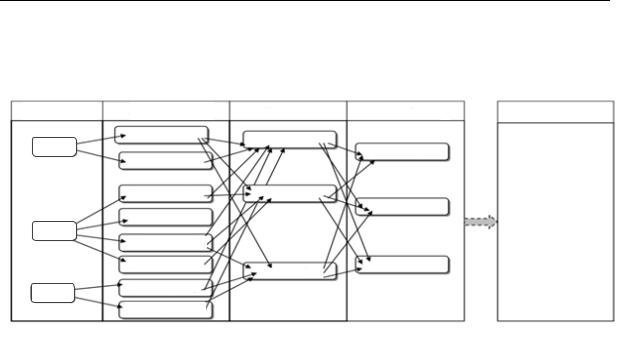
The hierarchical structureof the CDLis graphically shown in Fig. 3.
The fundamental structure of the CDL is a table of types of elements used, each element of characterized by two textual attributes. A fragment of this table for BIM of a typical development of the Voronezh region is shown in Table.
The next mandatory structure of the CDL is a table of standard sizes which assigns to each element of the table of types several elements that inherit all the attributes of the table of types with the addition of new data that have the format of an actual number and characterize the
101
Russian Journal of Building Construction and Architecture
geometric parameters of objects (e.g., the length and width for rectangular elements with the
possible addition of a radius curvatures for arched elements, etc.).
Types
Type 1
Type 2
Type n
Standard sizes
Standard sizes 1,1
Standard sizes 1,2
Standard sizes 2,1 Standard sizes 2,2
Standard sizes 2,3 Standard sizes 2,4 Standard sizes n,1
Standard sizes n,2
Cluster level 1 |
|
Cluster level 2 |
|
Cluster level 3 |
Cluster 1,1
Cluster 2,1
Cluster 1,2
Cluster
Standard sizes 2,3
Cluster 1,3
Fig. 3. Hierarchical structure of the combined dynamic libraryat the stage of identifying the total scope of work for the project
Furthermore, based on the primary structures, clusters of an increasing degree of integration are consistently designed. The attributes of the i-th cluster are a list of clusters of lower levels (in text format) with an indication of their number in the format of a short integer and/or standard sizes with an indication of their number in the form of integers or actual numbers.
Table
Segment of the type table for BIM of the typical construction of the Voronezh region
Type |
Technology |
Room door |
Metal plastic |
|
Wood |
|
Cardboard |
Entrance door |
Metal plastic |
|
Metal |
|
Wood |
Flight of stairs |
Monolith |
Stair railings |
Metal+wood |
|
Metal+plastic |
Surfacing |
Coating 1 |
|
Coating 2 |
|
Tile 1 |
|
Tile 2 |
So, e.g., based on the table of standard sizes, a first-order cluster «Wall» can be designed. To do this, the following set of parameters must be specified:
1)length, height, height of the lower part;
2)types of surfacings of the upper and lower parts;
102
Issue № 4 (52), 2021 |
ISSN 2542-0526 |
3)the number of standard sizes of windows, the number of each standard size, the distance of each standard size from the bottom edge to the floor;
4)the number of standard sizes of doors, the number of each standard size.
The horizontal coordinate characterizing the position of doors and windows has no influence on the volume of work, hence it is not included in the CDL. At the same time, an indication of the standard sizes of all elements is designed using the fundamental structures of the CDL and, within the framework of a relational RDMS, does not call for the repetition of textual attributes, but has an integer format, which causes a considerable decrease in the amount of analyzed and transmitted information. Clusters of the first order «Floor» and «Ceiling» are constructed similarly. Based on the first-order clusters, the second-order cluster «Premises» is desgined. Integration can be continued further by designing the third-order clusters «Floor» using the «Room» clusters. The limits of the increase in the degree of integration (thick arrow in Fig. 3) are identified by the stability and frequency of repetition in the practice of highorder clusters in actual construction conditions. In particular, for mass scale buildings it is possible to integrate within the entire structure.
At the same time, with any degree of integration, BIM, which is fully functional for the stage of identifying the scope of work on the project, is one-dimensional and is simply determined by the vector of clusters of a lower degree of integration. This approach enables one to completely address all of the obstacles to the widespread introduction of BIM technologies and procedures for the full life cycle of a construction project. Let us estimate the ratio of vector and raster BIM description in the simplest case of a 3D model of a room. A full raster grayscale description of six surfaces, even with a minimum size of 107 pixels and a minimum practically usable number of gradations equal to 16, requires specifying an array of ~ 109. The use of full color images considerably increases the amount of information required [26]. In contrast, a vector description, whose primitives are first-order clusters, only calls for six elements to be specified. Even while describing unique rooms directly through a nonclustered set of standard sizes, their number does not commonly exceed 101––102 and, more importantly, the components have a fixed number format.
Adding a list of works necessary for the formation of CDL elements allows one to desgin a BIM for the stage of identifying the scope of work for the project. Implemented in the Microsoft Office Access shell by the program, the CDL formation and analysis complex has the following functionality:
1.Hierarchical formation of sequential CDL elements up to the second stage of clustering based on the previous ones.
103

Russian Journal of Building Construction and Architecture
2.All higher-ranking clusters are automatically updated when data is refreshed.
3.Automatic analysis of CDL for connectivity and consistency.
4.Calculation of the scope of work required for the formation of CDLclusters.
5.Automatic updating is the amount of work required while updating data.
Conclusions. The high dimension of BIM of the full life cycle of a construction project curbs the implementation of information technology in the construction industry. The suggested BIM dimension reduction method based on a vector data model makes it possible to efficiently address the construction of a fully functional local information model for the stage of identifying the scope of work on a project. The resulting dynamic model has a hierarchical structure that describes objects of various degrees of integration, which makes it possible to effectively carry out BIM transfer between project participants, and the dynamic nature of the information model considerably expands the area of its practical application. The most effective framework for software implementation of a dynamic hierarchical library is relational database management systems. From a practical standpoint, the development of BIM of the full life cycle of a construction project calls for the agreement on the scope of work and non-stock resources for their implementation. It is also critical to investigate the dynamics of the project implementation. Besides, it is necessary to optimize the interaction of project participants based on BIM technology. These problems are to be tackled at the next stages of the study.
References
1.Remes J., Mischke J., Krishnan M. Solving the productivity puzzle: the role of demand and the promise of digitization. Int Product Monit, 2018, no. 35, p. 28.
2.Kassem M., Succar. B Macro BIM adoption: comparative market analysis. Autom Constr, 2017, no. 81, pp. 286––299.
3.Ivanov N. A., Vedeneev D. A., Shilova L. A. [Analysis of the introduction of industry4.0 technologies in the construction industry in the Russian Federation Construction system engineering. Cyberphysical building systems]. Sbornik materialov Vserossiiskoi nauchno-prakticheskoi konferentsii [Collection of materials of theAll-Russian Scientific and Practical Conference], 2019.
4.Gerbert P., Castagnino S., Rothballer C., Renz A., Filitz R. Digital in engineering and construction. The transformativepower of buildinginformation modelling. TheBoston consulting group, 2016, pp 2––18.
5.Barbosa F., Woetzel J., Mischke J., Ribeirinho M. J., Sridhar M., Parsons M., Bertram N., Brown S. Reinventing construction: a route to higher productivity. McKinsey& Company, 2017.
6.Zheng X., Le Y., Chan A.P.C., Hu Y., Li Y. Review of the application of social network analysis (SNA) in construction project management research. Int J Proj Manag, 2016, no. 34 (7), pp. 1214—1225.
7.Cinzia Talamo and Marcella M. Bonanomi The Impact of Digitalization on Processes and Organizational Structures ofArchitecture and Engineering Firms.
8.Richtlinienreihe VDI 2552 –– Aktuelle VDI-Schulungspartner für BIM-Basiskurse nach VDI/BS-MT 2552 Blatt 8.1, 2020.
9.Chuck L., Eastman Т. BIM handbook: а guide to building information modeling for owners, managers, designers, eпgiпeers and contractors. Hoboken, New Jersey, John Wiley& Sons, Inc., 2011. 648 p.
104
Issue № 4 (52), 2021 |
ISSN 2542-0526 |
10.Ginzburg А., Shilova L., Adamtsevich А., Shilov L. Implementation of BIM-technologies in Russian construction industry according to the international experience. Journal of Applied Engineering Science, 2016, no. 14 (4), pр. 457––460.
11.Ginzburg А. Г. LE IM: Living Environment Information Modelling. International Scientific Conference Environmental Science for Construction Industry, ESCI 2018; Но Chi Minh City; Viet Nam: MATEC Web of Conferences, 2018, vol. 193, p. 05030.
12.Ginzburg А. Sustainable Building Life Cycle Design. 5th International Conference on Topical Problems of Architecture, Civil Engineering, Energy Efficiency and Ecology, TPACEE-20 16; Tyumen State University ofArchitecture and Civil Engineering: MATECWeb of Conferences, 2016, vol. 73, p. 02018.
13.Volk R., Stengel Ј., Schultmann F. Building Information Modeling (BIM) for existing buildings –– Literature review and future needs. Automation in Construction, 2014, no. 38, pp. 109––127.
14.Ignatova E. U. Workspace Planning Based on the Analysis of BIM Collisions. Materials Science Forum, 2018, vo1. 931, pp. 1286–1290.
15.Volkov A. A., Gusakova E. A., Ovchinnikov A. N. [Development of the programming environment of information flows of the life cycle of a construction object]. Sistemotekhnika stroitel'stva. Kiberfizicheskie stroitel'nye sistemy [System engineering of construction Cyberphysical construction systems]. Moscow, MISI MFCYPubl., 2019, pp. 51––58.
16.Volkov A. A., Gusakova E. A., Ovchinnikov A. N. Problemy cyshchectvyyushchei cictemy yppavleniya zhiznennym tsiklom ob"ektov kapiral'nogo stroitel'stva i faktory, ix oppedelyayushchie [Problems of the existing life cycle management system of capital construction facilities and factors determining them].
Nayka i biznec: pyti razvitiya, 2019, no. 5 (95), pp. 38––42.
17.EU BIM Task Group. Handbook for the introduction of Building Information Modelling by the European Public Sector. 2018. Available at: http://www.eubim.eu/wp-con-tent/uploads/2017/07/EUBIM Handbook Web Optimized-1.
18.Sander SIEBELINK, Hans VOORDIJK, Maaike ENDEDIJK, Arjen ADRIAANSE Understanding barriers to BIM implementation: Their impact across organizational levels in relation to BIM maturity. Front. Eng. Manag, 2021, no. 8 (2), pp. 236––257.
19.Lucky M. N., Pasini D., Lupica Spagnolo S. Product data management for sustainability: an interoperable approach for sharing product data in a BIM environment. IOP conference series, Earth Environ Sci, 2019, vol. 296, p. 012053.
20.Rusu D., Popescu S. Decision-making ior enhancing building sustainability through life cycle. Appl Math Mech Eng, 2018, no. 61, pp. 191––202.
21.LapidusA. A.,Avetisyan R. T., Mirzakhanova A. T., Kazaryan R. R. [Prospects for the development of BIM technologies in the territory of the Russian Federation]. Sistemotekhnika stroitel'stva. Kiberfizicheskie stroitel'nye sistemy — 2019 [System engineering of construction. Cyberphysical Building Systems]. Moscow, 2019. MISI Publ.
22.Lucky M. N., Pasini D., Lupica Spagnolo S. Product data management for sustainability: an interoperable approach for sharing product data in a BIM environment. IOP conference series, Earth Environ Sci, 2019, vol. 296, p. 012053.
23.Gerbert P., Castagnino S., Rothballer C., Renz A., Filitz R. Digital in Engineering and Construction: The Transformative Power of Building Information Modeling. Boston: The Boston Consulting Group Inc.)
24.Mishchenko V. Ya., Gorbaneva E., Ovchinnikova E., Sevryukova K. Planning the optimal sequence for the inclusion of energy-saving measures in the process of overhauling the housing stock. Advances in Intelligent Systems and Computing, 2019, vol. 983, pp. 79––91.
25.Gorbaneva E. P., Mishchenko V. Ya., Sevryukova K. S., Ovchinnikova E. Using of a weighted directed acyclic graph for major repairs of real estate objects: the optimal combination of energy-efficient measures introduction. E3S WEB OF CONFERENCES. Ural Environmental Science Forum “Sustainable Development of Industrial Region” (UESF-2021), 2021, p. 09051.
26.David F., Rogers J. Alan Adams Mathematical Elements for Computer Graphics, MaGraw-Hill Publishing Cjmpany, New York – London, 2019. 605 p.
105

Russian Journal of Building Construction and Architecture
BUILDING MECHANICS
DOI10.36622/VSTU.2021.52.4.010
UDC624.21:533.6; 699.83
A. V. Kozlov 1, V. S. Safronov 2
NUMERICAL SIMULATION OF AERODYNAMIC STABILITY
OF LONG-SPAN BRIDGES *
Voronezh State Technical University 1, 2
Voronezh, Russia
1PhD in Engineering, Senior Lecturer of the Dept. of Design of Highways and Bridges, tel. (473) 271-52-02, e-mail: kozlov.a.v@inbox.ru
2Sc. D. in Engineering, Prof. of the Dept. of Structural Mechanics, tel. (473) 276-40-06, e-mail: vss22@mail.ru
Statement of the problem. The aim of the work is to simulate the resonant vibrations of the continuous beam span of the bridge in the direction perpendicular to the wind flow by the finite element method. The article deals with a non-standard situation that arose on May 20, 2010 on the bridge over the Volga River in the city of Volgograd.
Results. As a result, an effective algorithm for calculating the aerodynamic stability of large-span bridge structures was developed using one of the most widespread software systems in Russia and neighboring countries - "Lira-SAPR". Recommendations for the selection and modeling of dampers are given.
Conclusions. The developed algorithm makes it possible to numerically describe the disturbing force of periodic breakdown of wind flow vortices, which causes resonant oscillations of bridge spans, to apply this force to the design model in Lira-SAPR, and to obtain parameters that make it possible to assess the stress-strain state of the system during oscillations and to select the optimal characteristics of the damping devices.
Keywords: aerodynamic stability of bridges, resonance, damping devices.
Introduction. Research in the field of interaction of wind flow with bridge structures was carried out by both domestic [4–6, 9–11] and foreign scientists [1, 2, 7, 8, 12–18].
In publications in Russian, one of the most complete studies of the operation of beam structures in a wind flow is presented in the textbook [9], the theoretical and practical aspects of the aerodynamics of bridges are presented in the production publication [4]. The issues of the dynamic design of suspension bridges attracted the attention of a number of researchers immediately after the famous accident of the Tacoma Bridge in the USA in 1940.
© Kozlov A. V., Safronov V. S., 2021
* A part of the experimental studies has been carried out using the facilities of the Collective Research Center Named after Prof. Yu.M. Borisov, Voronezh State Technical University, which is partly supported by the Ministry of Science and Education of the Russian Federation, Contract No 075-15-2021-662.
106
Issue № 4 (52), 2021 |
ISSN 2542-0526 |
Until that time, numerous problems of interaction of an elastic structure with an air flow were studied by specialists in aircraft construction, and the corresponding field of knowledge was called aeroelasticity. The development of the theory of calculating aircrafts was based on fundamental theoretical results dating back to the works of N. E. Zhukovsky, a large number of experiments with models in wind tunnels and the experience of operating aircraft.
Progress in the field of aircraft construction has always been associated with an increase in the speed capabilities of new designs, the shapes of which have been continuously improved by improving streamlining, which made it possible to reduce power losses when moving in the air. Similar problems arose and were solved in the field of hydrodynamics and shipbuilding. Suspension and cable-stayed bridge structures are mainly formed on the basis of other considerations, mainly related to the need to ensure strength and rigidity under static influences. Moreover, the dynamic effects arising from the action of a temporary load are taken into account due to the conditional increase in the calculated static load by introducing dynamic coefficients. This approach is insufficient for solving problems related to the analysis of bridge vibrations under the influence of wind.
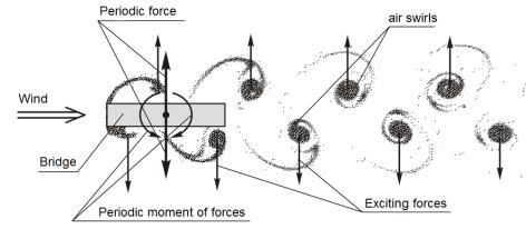
The air flow around obstacles is accompanied by the formation of a vortex wake (Fig. 1). Air vortices are formed directly behind the streamlined body, alternately to the right and left in the direction of the flow, losing contact with the obstacle with a certain frequency, and move in the direction of the flow, representing fairly stable formations.
Fig. 1. General scheme of vortex action (Karman track)
The frequency of vortex stripping is determined by the wind speed, the transverse size of the structure, and the Strouhal number:
S |
|
|
v b |
, |
(1) |
t |
|
||||
|
|
V |
|
||
|
|
|
cr |
|
|
where ν (Hz) is the frequency of vortex stripping, (at the critical wind speed it coincides with the natural frequency of flight); b (m) is the span rise; Vcr (m/s) is the critical wind speed.
107

Russian Journal of Building Construction and Architecture
The amplitude of the intensity of the periodic force of vortex stripping is calculated by the formula:
P 0.5 V2C b, |
(2) |
cr lat |
|
where ρ = 1.29 kg/m3 is the air density; Clat is the aerodynamic coefficient.
Thus, to calculate the critical wind speed and the amplitude of the periodic force, it is necessary to know 3 parameters: the frequency of the first form of natural oscillations of the spanv, the Strouhal number St and the aerodynamic coefficient Clat.
So, for the preliminary aerodynamic calculation for wind resonance, the initial data are the same as for the usual static calculation (static scheme, stiffness characteristics, constant loads). Additionally, it is only required to reliably determine 2 aerodynamic characteristics: the Strouhal number St and the aerodynamic coefficient Clat. At the stage of pre-design studies, they can be determined theoretically using Eurocode 4 [3].
1. Subject of research. Numerical modeling of the vortex resonance of a girder bridge is carried out on the example of a "dancing" bridge across the river Volga in Volgograd (Fig. 2). Traffic on the bridge was stopped on May 20, 2010 due to dispatchers reporting a strong swaying of the structure (while the structure was commissioned six months earlier). The survey did not reveal any defects and showed that the bridge was ready for use. In the morning of May 25, after a test drive of heavy trucks loaded with rubble, the movement of light vehicles on the bridge resumed.
Fig. 2. View of theroadway of the bridge during oscillations
108
Issue № 4 (52), 2021 |
ISSN 2542-0526 |
According to the conclusions of the expert group, the wind resonance was the cause of the oscillations. The magnitude of the amplitude was 0.4 m with the wind direction across the span and a speed of about 15––17 m/s; vibration frequency 0.4 Hz; period 2.5 s.
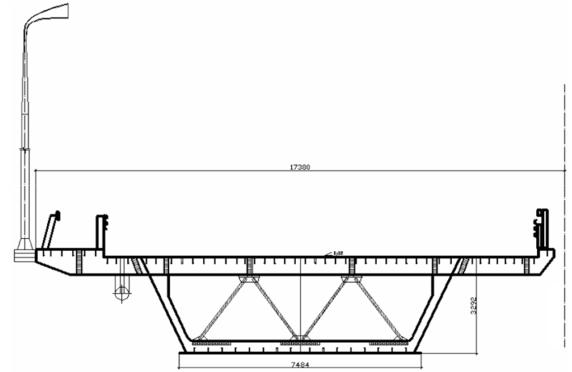
The span structure of the bridge under consideration is metal, box-section, continuous beam, with lower and upper orthotropic slabs (Fig. 3). The span structure is a continuous beam and is made according to the scheme 2 × 86.6 + 3 × 126 + 3 × 155 + 126 + 69 m. The dimension of the roadway is G-14.25 m (3 lanes). The width of the orthotropic slab is 17.38 m, the height of the main beam is 3.29 m.
Fig. 3. Cross-section of the superstructure
Oscillations have arisen in the middle part, which has the scheme 3 × 155 m. The Volga River in the construction area belongs to the first class of waterways, and according to regulatory requirements, navigable spans in the clear should be: downstream –– 140 m, upstream –– 120 m, this is the reason for such a large length of girder spans, which is not typical for both Russian and foreign bridges. At the same time, the low rise of the superstructure (3.29 m) should also be noted, which together makes the structure very flexible.
In Russian standards, the issue of calculating the aerodynamic stability of girder bridges was practically not considered before the case with the Volgograd bridge. At the time of the design of the bridge across the Volga, the regulatory documents mention the need to check only suspension and cable-stayed bridges for aerodynamic stability. In subsequent editions of these
109