

3507
.pdfRussian Journal of Building Construction and Architecture
beam increase resulting in the redistribution of forces. Thus in the practice of actual design of steel-reinforced concrete bridge spans, it is necessary to take into account the shear stiffness between the steel beam and the reinforced concrete slab of the carriageway.
In [3] for a hinge-supported single-span beam, an analytical dependence of the shift on the stiffness of the joint between a reinforced concrete slab and a steel beam in the span of a highway bridge was obtained:
|
|
n |
(1) |
x (x, ) m q (l 2x) Sred . |
|||
|
2 Ired |
|
|
Here δx is the displacement between the reinforced concrete slab and the supporting steel beam, mm; ς is the stiffness coefficient for shear bonds, t/m2 or kN/m2; l is the calculated span of the beam, m; q is a uniformly distributed load, t/m or kN/m; Sred is the static moment of the steel part of the section to the level of the joint, m3; Ired is the moment of inertia of a single steel-reinforced concrete section, m4. For the hinge-supported single-span beam, the values of the constants m = 0.36, n = 0.87 are obtained which are confirmed by means of finite-element calculations under a variety of loads for beams of different sections and span lengths selected according to [6, 8, 14, 18].
Obviously, for continuous multi-span beams with different spans, various loads in spans and stiffness, the dependence (1) should have varying values of m and n for the sections with positive and negative bending moments. Using the numerical experiments similar to those performed for the single-span beam, it was found that regardless of the span length, their number, length ratio, and geometric parameters of the constituent elements (both common for the entire continuous beam and spans differing in size), the position of the section in question (in the extreme or the middle span ) and the shear forces for ς ≥ 20.000 t/m2, the relationships between the displacement and the shear stiffness of the joint ς are as follows:
|
|
|
0.97 |
(2) |
x (x, ) 0.76 q (l 2x) Sred |
; |
|||
|
2 Ired |
|
|
|
|
|
|
0.75 |
(3) |
x (x, ) 0.18 q (l 2x) Sred |
. |
|||
|
2 Ired |
|
|
|
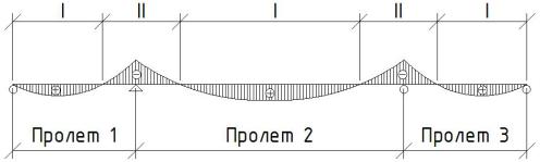
In addition, in the sections I with the positive moments (Fig. 1), the formula (2) should be employed, in the sections II with the negative moments, the formula (3) should be employed, i.e., the values of the constants in (1) equal: m = 0.76, n = 0.97 and m = 0.18, n = 0.75 for the sections with the positive and negative moments, respectively.
100
Issue № 1 (45), 2020 |
ISSN 2542-0526 |
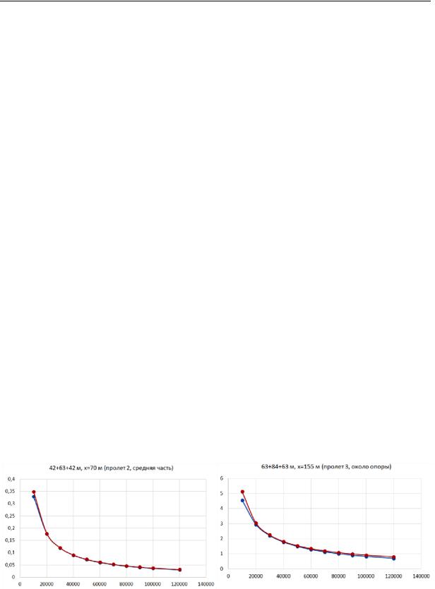
Fig. 2—6 shows the graphical dependences of the shear displacement δx (ordinate axis, mm) on the shear stiffness of the joint ς (abscissa axis, t/m2) are presented for the numerical experiment (blue curves) and analytically by means of the formula (2) and (3) (brown curves) for various arbitrary schemes of the continuous beams with the shear stiffness ranging from 10.000 to 120.000 t/m2.
|
|
|
|
|
Span 1 |
Span 2 |
Span 3 |
||
|
|
|
|
|
Fig. 1. Scheme for the continuous three-span beam with the typical areas of the bending moments
Hence for the hinge-supported beams, the calculation of the dependence of the absolute value of the plate slippage on the beam on the shear stiffness δx = f(x, ς) is calculated using three formulas depending on the static structure of the beam and the position of the calculated section (Table).
Таble
Functional dependence δx = f(x, ς)
|
|
|
|
|
q (l 2x) Sred |
0.87 |
||
|
One-span beam |
x 0.36 |
|
|
|
|||
|
2 Ired |
|
||||||
|
|
|
|
|
|
|
||
|
|
|
|
|
|
|
|
|
|
Positive bending moment |
x 0.76 |
|
|
q (l 2x) Sred |
|
0.97 |
|
|
(areas I, Fig. 1) |
|
|
|
|
|||
|
|
2 Ired |
|
|||||
Multi-span beam |
|
|
|
|
|
|||
|
|
|
|
|
|
|
|
|
Negative bending moment |
x 0.18 |
|
|
q (l 2x) Sred |
|
|
0.75 |
|
|
(areas II, Fig. 1) |
|
|
|
||||
|
|
|
||||||
|
|
|
|
2 Ired |
|
|
||
In [3], integral equalities are shown making it possible to determine the upper limit of shear stiffness for the single-span beam where the span of the bridge can be calculated using the classical model of flat sections without taking into account the shift between the reinforced concrete slab and the steel beam. The upper limit of the shear stiffness for the arbitrary section х from the start of the continuous multi-span beam can be determined using the generalized
101
Russian Journal of Building Construction and Architecture
integral equation for Nς, the total shear force in the joint accumulated along the length of the structure from the start to the section in question:
|
x |
|
|
|
Qэкв.1(x) Sred |
|
|
n1 |
x |
|
|
Qэкв.2(x) Sred |
|
n2 |
|
|
||||||||||
|
1 |
|
|
|
|
2 |
|
|
|
|
||||||||||||||||
N |
m1 |
|
|
dx |
m2 |
|
dx |
|
||||||||||||||||||
|
|
|
|
|
|
|
|
|||||||||||||||||||
|
|
|
|
|
|
|
||||||||||||||||||||
|
0 |
|
|
|
Ired |
|
|
|
|
|
|
x |
|
|
Ired |
|
|
|
|
|
|
|
||||
|
|
|
|
|
|
|
|
|
|
|
|
|
|
1 |
|
|
|
|
|
|
|
|
|
|
|
|
x |
|
|
|
|
|
n2 |
|
|
|
x |
|
Qэкв.4(x) Sred |
|
n1 |
|
|
|
|
|
|||||||
|
3 |
|
|
|
|
|
|
|
|
|
4 |
|
|
|
|
|
|
|
||||||||
m2 |
|
Qэкв.3(x) Sred |
|
|
|
|
|
dx m1 |
|
|
|
dx ... |
(4) |
|||||||||||||
|
|
|
|
|
|
|
|
|
|
|||||||||||||||||
x |
2 |
|
|
|
Ired |
|
|
|
|
|
|
|
x |
|
|
|
Ired |
|
|
|
|
|
|
|
|
|
|
|
|
|
|
|
|
|
|
|
|
|
|
3 |
|
|
|
|
|
|
|
|
|
|
|
|
|
|
x |
|
|
|
|
|
|
|
n2 |
x |
|
|
|
|
|
|
n2 |
|
|
|||||||
|
5 |
|
|
|
|
|
|
|
6 |
|
|
|
|
|
|
|
|
|||||||||
N m2 |
Qэкв.5(x) Sred |
|
|
|
dx m2 |
Qэкв.6(x) Sred |
|
|
|
dx ... |
|
|||||||||||||||
|
|
|
|
|
|
|
||||||||||||||||||||
|
x |
|
|
|
Ired |
|
|
|
|
|
x |
|
|
Ired |
|
|
|
|
|
|
|
|||||
|
4 |
|
|
|
|
|
|
|
|
|
|
|
|
5 |
|
|
|
|
|
|
|
|
|
|
|
|
In the equality (4):
––the area (0; х1) is the extreme section with a positive bending moment in the first span of the continuous beam according to Fig. 1, (х1; х2) is the portion in the first span of the continuous beam with a negative moment adjacent to the first intermediate support, (х2; х3) is the portion in the second span of the continuous beam with a negative moment adjacent to the first intermediate support, (х3; х4) is the portion in the second span with a positive bending moment, (х4; х5) is the portion in the second span of the continuous beam with a negative moment adjacent to the second intermediate support, (х5; х6) is the portion in the third span of the continuous beam with a negative moment adjacent to the second intermediate support, etc., up to the area where the section in question is located;
––Qequiv.1(х), …, Qequiv.6(х) are the values of the equivalent transverse force Q calculated for each section using the distributed load q in the section х from the start of the beam;
––m1 = 0.76, n1 = 0.97 are the constants in the formula (2) for the areas I with positive moments (Fig. 1);
42 + 63+ 42 m, x = 70 m (Span 2, Middle part) |
|
63 + 84+ 63 m, x = 155 m (Span 3, Adjacent to the support) |
|
|
|
Fig. 2. Comparison of the numerical (blue curve) |
Fig. 3. Comparison of the numerical (blue curve) and |
and analytical (2) (brown curve) of the dependences |
analytical (3) (brown curve) of the dependences for the |
for the middle span of the continuous beam according |
area adjacent to the support of the continuous beam ac- |
to the scheme 42 + 63 + 42 m, positive moment |
cording to the scheme 63 + 84 + 63 m, negative moment |
102
Issue № 1 (45), 2020 |
ISSN 2542-0526 |
–– m2 = 0.18, n2 = 0.75 are the constants in the formula (3) for the areas II with negative moments (Fig. 1).
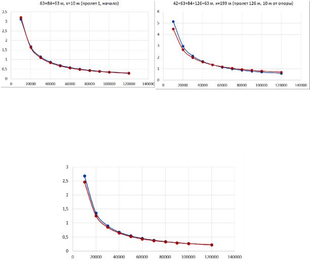
63+ 84 + 63 m, x = 10 m (Span 126 m, Span 1, Start) |
|
42 + 63+ 84 + 126 + 63 m, x = 199 m (Span 126 m, 10 m from the support) |
|
|
|
|
|
|
Fig. 4. Comparison of the numerical (blue curve) and |
Fig. 5. Comparison of the numerical (blue curve) and |
analytical (2) (brown curve) of the dependences for the |
analytical (3) (brown curve) of the dependences for the |
start of the first span of the continuous beam according |
area adjacent to the maximum span of the continuous |
to the scheme 63 + 84 + 63 m, |
beam according to the scheme |
positive moment |
42 + 63 + 84 + 126 + 63 m, negative moment |
42 + 63+ 84 + 126 + 63 m, x = 234 m (Third of the span of 126 m)
Fig. 6. Comparison of the numerical (blue curve) and analytical (2) (brown curve) of the dependences for the area adjacent to the maximum span of the beam according to the scheme 42 + 63 + 84 + 126 + 63 m, positive moment
It was recommended that the limit value of Nς for continuous multi-span beams should be determined according to the notes for Table 9.4—9.6 of the Set of Guidelines (СП) 35.13330.2011 “Bridges and Pipes. Actualized Edition of the Construction Guidelines and Regulations (СНиП) 2.05.03.84”.
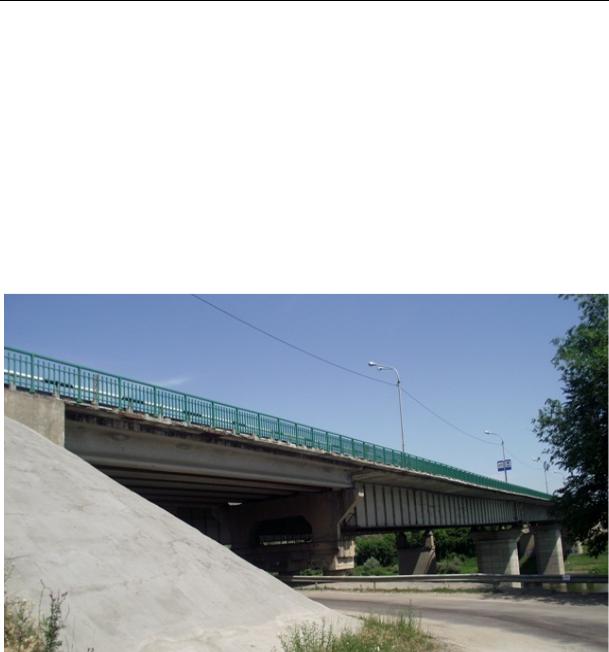
2. Example of the practical application of the developed calculation method on an actual object. As the justification for taking into account the flexibility of the joint of a steel beam with a reinforced concrete slab of the carriage lane, we are looking into the bridge over the Don River at 214 + 681 km of the Kursk –– Voronezh R-298 highway (the R-22 Caspiy highway in the Voronezh Region) (Fig. 7).
103
Russian Journal of Building Construction and Architecture
The scheme of the bridge 21+(63×3)+33×2, the central part is made in the form of a 3-span continuous steel-reinforced concrete beam with the span of 3 × 63 m according to the standard Lengiprotransmost design 3.503-50. The bridge was built in 1991, in 2008 and 2013 surveys were carried out that indicated a sag of the first span of the steel-reinforced concrete part, in 2008 the sag amounted to 136 mm and to 165 mm in 2013. Thus, over 5 years, sagging increased significantly, by 29 mm, with no additional coating layers and other visible damage. This increase in sagging caused by the factors which had not not recognized until the reconstruction began, is of significant interest in terms of the calculation justification of the state of rigid support by means of the methodology set forth in the paper.
Fig. 7. General view from the right-hand side prior to the reconstruction
As part of the 2015—2016 reconstruction of the bridge, a prefabricated reinforced concrete slab of the carriageway with a monolithic slab was completely replaced. During the dismantling of the slab, the unsatisfactory condition of the concrete was detected in the filling of the windows of the first span of the prefabricated slabs where the rigid supports were set up, which, in fact, is a typical defect for this type of combination. However, during the inspection process, the state of concrete by monolithic windows could not be identified using nondestructive methods. The only indirect sign to lead us to assume that they were in an unsatisfactory condition was traces of leaks with leaching on the lower surface of the plates.
104
Issue № 1 (45), 2020 |
ISSN 2542-0526 |
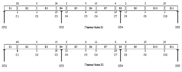
The openings of the joints of the steel beam were measured that showed that the beam was originally designed with a construction lift and the friction joints of the mounting blocks remained in a good condition and did not cause sagging. According to Fig. 8 there are disclosure (clearance) values for the chords in millimeters away at the time of the survey (September 2013). The values of the joints disclosure indicate that the main beams were mounted with a construction lift (in the middle of the spans, the joints disclosed above are mostly larger than those below) and there were no disruptions in the operation of the joints.
Support 2 |
|
Support 3 |
|
Main beam B1 |
|
Support 4 |
|
Support 5 |
Support 2 |
|
Support 3 |
|
Main beam B2 |
|
Support 4 |
|
Support 5 |
Fig. 8. Scheme of the location of the blocks and joints of the main beams:
slots B1 and B11 are 15.75 m in length; B4, B6, B8 are 10.5 m in length; the remainder are 21 m in length each
Let us look at the evaluation of the load-carrying capacity of the superstructure according to the results of calculating the cross section in the area of the joint C2, as the sagging of the span was detected at this very spot according to the classical method and to the approach set forth in this paper considering the flexibility of the joint of the steel and reinforced concrete parts.
Calculation using the classical method. The calculation was performed for loads of A11 and H11 class in compliance with the Set of Guidelines (СП) 35.13330.2011.
According to a typical design, the moments of resistance of the steel section for the upper fiber are Wн.ст. = 140200 сm3, for the lower fiber Wв.ст. = 74300 сm3, the moment of resistance of the reinforced concrete slab in the combined section Wб.ст.б. = 727517 сm3. The normal stresses in concrete at the level of the center of gravity of the slab must meet the following condition:
|
|
|
M II |
|
|
b |
|
2 |
m R , |
|
||||
|
|
|
b b |
|
|
|
|
nbWб.ст.б. |
|
where mb = 1.2 is the coefficient accounting for the stresses balanced in the transverse joint section occurring at the level of the center of gravity of the slab depending on concrete creep,
105

Russian Journal of Building Construction and Architecture
heaving and changes of the temperature; Rb = 1325 t/m2 is a design compression resistance of В25(М400) class concrete in compliance with section 7.24 of the Set of Guidelines (СП) 35.13330.2011; nb = 6.0 is the reduction coefficient (according to the project design).
|
|
|
|
|
|
|
|
|
|
|
|
|
|
2907.7 |
|
|
|
|
|
666.1 т |
/ m2 m R 1590 т/ m2; |
|
|||||||||||||||||||||||||||
|
|
|
|
|
|
|
|
|
6 |
727517 10 6 |
|
||||||||||||||||||||||||||||||||||||||
|
|
|
|
|
|
|
|
b |
|
|
|
|
|
|
|
|
|
|
|
|
|
|
|
|
b |
b |
|
|
|
|
|
|
|
|
|||||||||||||||
|
|
|
|
|
|
|
|
|
|
|
|
|
2907.7 |
|
|
|
|
|
|
3880.3 т/ m2 |
m R 27000 т/ m2. |
|
|||||||||||||||||||||||||||
|
|
|
|
|
|
1.03 |
727517 10 6 |
|
|||||||||||||||||||||||||||||||||||||||||
|
|
|
|
|
|
r |
|
|
|
|
|
|
|
|
|
|
|
|
|
|
|
|
|
r |
r |
|
|
|
|
|
|
|
|
||||||||||||||||
The normal stresses in the lower chord of the steel beam are |
|
|
|
|
|
|
|
|
|
||||||||||||||||||||||||||||||||||||||||
|
|
|
|
|
|
|
|
|
|
|
|
|
|
|
н.п. |
M max z |
bs |
N |
br |
|
|
N |
|
m Ry |
; |
|
|
|
|
|
|
|
|||||||||||||||||
|
|
|
|
|
|
|
|
|
|
|
|
|
|
|
|
2 |
|
|
|
|
|
|
|
|
br |
|
|
|
|
|
|
|
|||||||||||||||||
|
|
|
|
|
|
|
|
|
|
|
|
|
|
|
|
|
|
Wн.ст. |
|
|
|
|
|
A |
|
|
|
|
|
|
|
||||||||||||||||||
|
|
|
|
|
|
|
|
|
|
|
|
|
|
|
|
|
|
|
|
|
|
|
|
|
|
|
|
|
|
|
|
|
|
s |
|
|
|
|
|
|
|
|
|
||||||
|
|
|
|
|
|
|
|
|
|
|
|
|
|
|
|
|
|
|
|
|
|
|
|
|
|
|
|
|
|
|
|
|
|
|
|
|
|
|
|
|
|
|
|
|
|||||
|
|
|
|
N |
br |
A |
b |
A |
r |
12602 10 4 666.1 48 10 4 |
3880.3 858 т; |
|
|||||||||||||||||||||||||||||||||||||
|
|
|
|
|
|
|
|
|
b |
|
|
r |
|
|
|
|
|
|
|
|
|
|
|
|
|
|
|
|
|
|
|
|
|
|
|
|
|
|
|
|
|
|
|
|
|
||||
|
|
н.п. |
4522.9 2.395 858 |
|
|
|
|
858 |
|
|
|
26448 |
т/ m2 m R |
y |
30000 т |
/ m2. |
|||||||||||||||||||||||||||||||||
|
|
970 10 4 |
|||||||||||||||||||||||||||||||||||||||||||||||
|
|
|
|
|
140200 10 6 |
|
|
|
|
|
|
|
|
|
|
|
|
|
|
|
|
|
|
|
|
|
|
|
|
|
|
||||||||||||||||||
The normal stresses in the upper chord of the steel beam are |
|
|
|
|
|
|
|
|
|
||||||||||||||||||||||||||||||||||||||||
|
|
|
|
|
|
|
|
|
|
|
|
|
|
|
|
|
M max |
z |
bs |
N |
br |
|
|
|
N |
br |
m m R |
; |
|
|
|
|
|
||||||||||||||||
|
|
|
|
|
|
|
|
|
|
|
|
|
|
в.п. |
|
|
|
2 |
|
|
|
|
|
|
|
|
|
|
|
|
|
||||||||||||||||||
|
|
|
|
|
|
|
|
|
|
|
|
|
|
|
|
|
|
|
|
|
|
|
|
|
|
|
|
|
|
|
|
|
|
||||||||||||||||
|
|
|
|
|
|
|
|
|
|
|
|
|
|
|
|
|
|
|
|
|
|
|
Wв.ст. |
|
|
|
|
|
|
|
A |
2 |
|
|
y |
|
|
|
|
|
|
||||||||
|
|
|
|
|
|
|
|
|
|
|
|
|
|
|
|
|
|
|
|
|
|
|
|
|
|
|
|
|
|
|
|
s |
|
|
|
|
|
|
|
|
|
|
|
||||||
|
|
|
|
|
|
|
|
|
|
|
|
|
|
|
|
|
|
|
|
|
|
|
|
|
|
|
|
|
|
|
|
|
|
|
|
|
|
|
|
|
|
|
|
|
|
||||
|
|
|
|
4522.9 2.395 858 |
|
|
|
|
858 |
|
|
24371 т/ m2 |
m |
|
m R |
|
36000 т/ m2. |
||||||||||||||||||||||||||||||||
|
|
|
74300 10 6 |
|
|
|
970 10 4 |
|
|
||||||||||||||||||||||||||||||||||||||||
|
в.п. |
|
|
|
|
|
|
|
|
|
|
|
|
|
|
|
|
|
|
|
|
2 |
|
|
|
|
y |
|
|
||||||||||||||||||||
The coefficient m2 is introduced with no account of the plate unloading the upper chord. In this case σb < 0.8 Rb, thus m2 = 1.2. All of the tests are performed indicating that the span corresponds to the load classes of A11 and H11 loading classes. Note that in the other characteristic sections (above the supports and in the middle of the second span), all of the tests performed according to the hypothesis of flat sections were met.
In the numerical calculations in the LIRA-SAPR software package by means of the finite element model with an unstable joint of a reinforced concrete slab with a steel beam and the same loads for normal stresses in the lower zone of the steel beam, the value σн.п. = 26524 t/m2, in the upper zone σв.п. = 24054 t/m2. The results are in good agreement with those presented above.
Numerical calculation with a stable joint. Let us design a calculation model in the LIRACAD software package based on the following assumption. If from 2008 to 2013 there was an increase in the sagging span of 29 mm, but the condition of the joints of steel beams is good and indicates an initial construction rise; lengthy processes in a reinforced concrete slab (shrinkage and creep) were expected to be over long before the increase in sagging; extra coating layers did not fit, the only cause of an increase in the sagging over a rather short period of time is a decrease in the shear stiffness of the joint. This is exactly what was shown in
106
Issue № 1 (45), 2020 |
ISSN 2542-0526 |
the further dismantling of the slabs during the reconstruction due to the degradation of concrete of the windows of monolithic supports.
The opposite task was solved in order to quantitatively reduce the shear stiffness of the supports: by selecting the shear stiffness in the finite element model it turns out that an increase in the deflection from the constant load by 29 mm occurs when the linear shear stiffness of the joint decreases to 1000 t/m2 (despite the fact that for rigid supports in a perfect condition, the value should be 3 orders of magnitude higher, around 130.000 t/m2). Thus, in this case we can conclude that there is an almost complete disruption in the operation of the supports. The load-carrying capacity of the structure with such shear stiffness will be reduced.
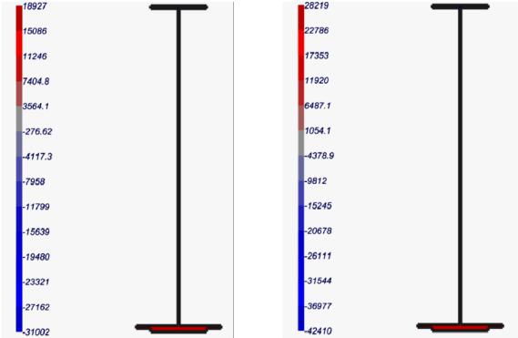
Fig. 9 shows the numerical calculation of the isofield of the normal stresses in a steel beam (the upper shelf is at the bottom so that the stress ranges from negative to positive values) with the joint stiffness of 1000 t/m2.
Fig. 9. Isofields of the normal stresses in the steel beam:
а) from the constant loads b) from the constants in combination with А11
Taking into account the coefficient m2 = 1.2 considering the unloading effect of the plate on the upper belt (as was assumed in the calculation using the classical method), the limit stress for the upper belt from constant loads is 31002 t/m2, it does not exceed the maximum allowable
107

Russian Journal of Building Construction and Architecture
36000 t/m2. But the limit stress from constant loads in combination with A11 is 42.410 t/m2, which is already over the maximum allowable value. According to the increase in sagging, if we accept the shear stiffness of the joint 1000 t/m2, then the load-carrying capacity of the span is not provided, and the allowable load class is [(36000−31000) / (42410−31000)] × 11 = 0.44 × × 11 = 4, 8, which is much lower than the standard value. Hence the calculation of steelreinforced concrete bridge spans considering the shear stiffness of the connecting joint yields a loading capacity which is considerably different from the one obtained using the classical method. This difference is particularly distinguishable for operating facilities where the connection of concrete with a steel beam can be severely disrupted in relation to the design values.
Note that the theoretical value of the plate shear along the beam at the specified joint stiffness of 1000 t/m2 is 4.4 mm at the end and 0.34 mm in total in the section in question. Therefore even if shear measurement was part of the investigation, such values can barely be detected, particularly in the case of damage to the concrete slab in the area of the expansion joint. The above example is indicative of the inconsistency of the definition in section 6.6.1.1 of the Eurocode [11, 12] for an unstable joint, which sets the value of the maximum shift at 6 mm, lower than which the joint should be considered unstable.
Conclusions. In the course of the numerical experiments, it was found that in the presence of a shear in the connecting joint between the steel beam and the reinforced concrete plate of the steel-reinforced concrete spans of the bridge structures, there is a significant redistribution of stresses between the beam and the plate. Thus while designing steel-reinforced concrete bridge spans, it is essential to consider the shear stiffness between the steel beam and the reinforced concrete slab of the carriageway, which is confirmed by a practical calculation example for an actual object.
According to the numerical experiments, new analytical formulas for the displacement of a reinforced concrete slab along a steel beam depending on the shear stiffness of the joint are obtained for a multi-span hinge-supported continuous beam under a load uniformly distributed over its entire length.
A generalized integral equation is presented making it possible to identify the upper limit of the shear stiffness above which the classical approach can be employed for calculating mul- ti-span continuous steel-reinforced concrete structures under the assumption that there is no shear.
In actual design practices, they enable one to obtain more accurate stress distribution fields in composite structures of steel-reinforced concrete spans of bridges.
108
Issue № 1 (45), 2020 |
ISSN 2542-0526 |
References
1.Belutskii I. Yu. Sovershenstvovanie metodov rascheta i otsenki rabotosposobnosti ekspluatiruemykh stalezhelezobetonnykh proletnykh stroenii. Diss. dokt. tekhn. nauk [Improvement of methods for calculating and evaluating the operability of steel-reinforced concrete spans in operation. Dr. eng. sci. diss.]. Khabarovsk, 2004.
286p.
2.Belutskii I. Yu., Yatsura V. G. Otrazhenie kontseptsii I. M. Rabinovicha v kharakteristike raboty stalezhelezobetonnykh proletnykh stroenii kak sostavnykh s antagonisticheskimi svyazyami [Reflection of I. M. Rabinovich's concepts in the characterization of steel-reinforced concrete superstructures as composite structures with antagonistic connections]. Stroitel'naya mekhanika i raschet sooruzhenii, 2015, no. 5, pp. 2—8.
3.Eremin V. G., Kozlov A. V. Analiticheskaya zavisimost' smeshcheniya ot sdvigovoi zhestkosti shva mezhdu zhelezobetonnoi plitoi i stal'noi balkoi v proletnykh stroeniyakh mostov [Analytical dependence of displacement on the shear stiffness of the joint between a reinforced concrete slab and a steel beam in bridge spans]. Nauchnyi zhurnal stroitel'stva i arkhitektury, 2019, no. 3 (55), pp. 94—104.
4.Kozlov A. V. Raschet stalezhelezobetonnykh mostov s uchetom sdviga plity po verkhnemu poyasu balki [Calculation of steel-reinforced concrete bridges taking into account the shift of the plate along the upper belt of the beam]. Stroitel'naya mekhanika i konstruktsii, 2018, no. 4 (19), pp. 64—71.
5.Kozlov A. V., Kozlova A. V. [Application of "LIRA-CAD" for modeling the life cycle of a structure in the calculations of bridge structures]. Trudy Vserossiiskogo foruma «BIM. Proektirovanie. Stroitel'stvo. Ekspluatatsiya» [Proc. of the all-Russian forum "BIM. Design. Construction. Operation"]. Voronezh, VGTU Publ., 2018, pp. 10—21.
6.Korneev M. M. Stalezhelezobetonnye mosty: teoreticheskoe i prakticheskoe posobie po proektirovaniyu
[Steel-reinforced concrete bridges: a theoretical and practical guide to design]. Saint Petersburg, FGBOU VPO PGUPS Publ., 2015. 400 p.
7.Marukhin B. A. [To build a model of the work of connecting elements of steel-reinforced concrete bridges taking into account the multi-cycle loading]. Novye idei novogo veka: v 2 ch. Ch. 2 [New ideas of the new century: in 2 vol. Vol. 2]. Khabarovsk, TOGU Publ., 2009. P. 309—316.
8.ODM 218.4.027-2016. Metodicheskie rekomendatsii po opredeleniyu gruzopod"emnosti ekspluatiruemykh mostovykh sooruzhenii na avtomobil'nykh dorogakh obshchego pol'zovaniya. Metallicheskie i stalezhelezobetonnye konstruktsii [ODM 218.4.027-2016. Methodical recommendations on determination of the carrying capacity of the exploited bridge structures on motor roads of General use. Metal and steel-reinforced concrete structures]. Moscow, Federal'noe dorozhnoe agentstvo (Rosavtodor) Publ., 2016. 127 p.
9.Reshetnikov V. G. Novye effektivnye konstruktsii stalezhelezobetonnykh proletnykh stroenii mostov. Diss. kand. tekhn. nauk [New efficient designs of steel-reinforced concrete bridge spans. Cand. eng. sci. diss.]. Moscow, 2002. 139 p.
10.Streletskii N. N. Stalezhelezobetonnye proletnye stroeniya mostov [Steel-reinforced concrete bridge spans]. Moscow, Transport Publ., 1981. 360 p.
11.Tekhnicheskii kodeks ustanovivsheisya praktiki TKP EN 1994-2-2009 (02250) Evrokod 4. Proektirovanie stalezhelezobetonnykh konstruktsii. Ch.' 2. Osnovnye printsipy i pravila dlya mostov [Technical code of established practice of the tap EN 1994-2-2009 (02250) Eurocode 4. Design of steel-reinforced concrete structures.
109