

3231
.pdfIssue № 1 (49), 2021 |
ISSN 2542-0526 |
support ribs 20 mm in thickness. At the nodes of the ends of the ribs, links are installed that limit vertical linear displacements. The width of the supporting ribs and stiffeners is assigned to the width of the chords (shelves). The beam interface is comprised of three horizontal rows of M20 bolts with a pitch of 75 mm in height (two bolts in each row). The installation gap of 20 mm is filled with steel gaskets. The bolts and mounting spacers are modeled by means of one-way two-node ties [5, 7, 10]: the bolts operate in tension and disengage during compression, while the mounting spacers operate in compression and disengage during stretching (Fig. 3).
Loading combination 2
kN/m |
Loading combination 1 |
kN/m |
Plane connections |
Step |
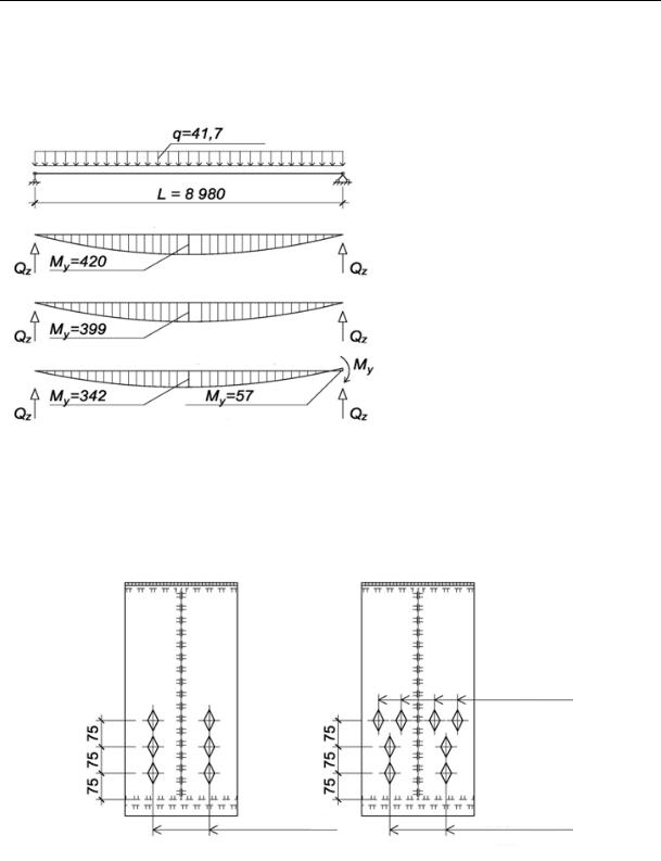
Fig. 1. Design scheme for steel beams
Mounting gaskets
Bolts
Step
Fig. 2. Transverse section of the steel beam Fig. 3. General view of the support node of the FE-beam model
The volumetric model was designed in the environment of the SCAD Office software using the following type of finite element (FE) [3, 4, 9]: type 36 eight-node, isoparametric FE. The FE-model of two beams has the following computational dimension: 27636 nodes, 18126 elements, 82.768 degrees of freedom. The wall is divided in height into eight rows of FE, shelves and supporting ribs are divided into ten rows of FE in width. Each steel beam element is
21

Russian Journal of Building Construction and Architecture
modeled using two rows of volumetric FE in thickness. In this case, the following dimensions of isoparametric eight-node FE were employed: wall –– 75 × 75 × 3 mm, shelf overhangs –– 40 × 75 × 8 mm, support ribs –– 40 × 75 × 10 mm, stiffeners –– 37 × 75 × 5 mm. Connections in the form of constraints on linear displacements are set so that the fixing conditions correspond to the constructive solution of the junction of the elements: with hinged-fixed and hinged-movable supports [2, 8].
2. Methodology for identifying the VAT for the core design scheme. Diagrams of normal and tangential stresses were designed in the section coinciding with the geometric centers of the second vertical row of the FE of the I-beam model wall, with a tie from the edge of the supporting edge of the beam x = 132.5 mm, as it is in this row in the junction of the beams that FE have the highest concentration stress.
For a bar design scheme, the stress values are identified using the known expressions [2]:
|
Qz Sx , |
(1) |
|
Ixtw |
|
M y y / Ix , |
(2) |
|
where Qz, My are the values of the shear force and bending moment in the corresponding section; Sx is the static moment of the cut-off part of the section relative to the x - x axis; Ix is the moment of inertia ofthetotalsectionrelativeto thex - x axis;tw is thewall thickness oftheI-beam;y isthe coordinatemeasuredfromthex- x axistotheconsideredfiber ofthecrosssection.
As for loading the hinged beam with a uniformly distributed load q along the entire length, the values of internal forces are identified based on the following relationships:
Qz q(L 2x)/2, |
(3) |
M y qx(L x)/2, |
(4) |
where q is the value of the intensity of the uniformly distributed design load; Qz, My are the values of shear force and bending moment for a cross section at a distance x; x is the coordinate for identifying internal efforts; L is the beam span.
3. Analysis of the numerical and analytical results of the study. Below are the results of calculating volumetric models of beams in the form of fields of distribution of normal and tangential stresses (Fig. 4, 5, 6). Fig. 7 shows the horizontal displacements on the support sections.
Free rotation of the supporting part of the beam starts from the top row of bolted connections. In the section of the section, below the axis of the upper row of bolts, there is a partial pinching of the beam with the transfer of a part of the bending moment. Let us look into how the stresses in the FE located in the second vertical row of the beam support compartment change for combina-
22
Issue № 1 (49), 2021 |
ISSN 2542-0526 |
tionsofloadcases№1,№2ofthemodel(Fig.8a,b)andacombinationofloadcases№1forthe barscheme(Fig.8c).
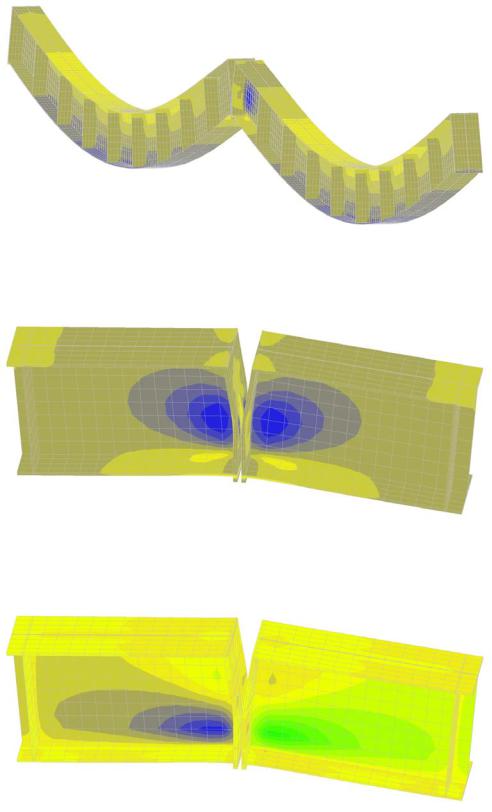
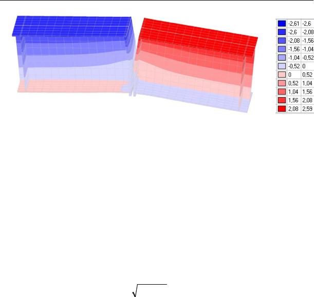
Fig. 4. General view of the mosaic of normal stresses σ (combination of load cases № 1)
Fig. 5. Mosaic of the normal stresses σ at the support node (combination of load cases № 1)
Fig. 6. Mosaic of the shear stresses τ at the support node (load combination № 1)
23
Russian Journal of Building Construction and Architecture
Fig. 7. Mosaic of the distribution of horizontal displacements in mm (combination of load cases № 1)
The stress diagrams indicate (Fig. 8, 9) that the values and nature of the stress-strain of the I-beam in the reference section of the FE model and the bar scheme differ significantly. Moreover, the case of a symmetrical load (combination of load cases № 1) is more dangerous and shows the maximum values of normal and shear stresses. It is assumed that this is caused by the partial compatibility of the operation of the supporting ribs of adjacent beams. The support section of the right, less loaded, beam unloads the support section of the left, more loaded, beam. If the values are inserted into the strength condition (44) SP 16.13330.2017 with the simultaneous action of a bending moment and a shear force for steel S255 at the most stressed point A according to Fig. 9a, b, we get:
0.87 |
2x 3 2xy |
1, |
(5) |
|
|||
Ry c |
|
|
|
(6) where Ry is the design steel resistance to yield strength; γс is the operating condition factor; σx is the normal stress; τxy is the tangential stress.
The condition for checking the strength at point A is not satisfied. It is essential to make a beam wall on the support section from steel of strength class C355 or to increase the wall thickness in the support compartment by assigning a wall thickness of 8 mm. But partial pinching of the beam not only raises the stresses from the bending moment in the support section, but also reduces the magnitude of the moment in the span [13, 22].
Let us examine the nature of the distribution of the bending moment: for the FE models of two beams (previously described) with partial restraint, for the FE model of a single beam without partial restraint (horizontal ties are imposed for the right support at the nodes at the level of the lower flange) and the bar scheme of a statically definable beam. The values of
24
Issue № 1 (49), 2021 |
ISSN 2542-0526 |
bending moments for FE-models were identified using the expression (2). The values of the normal stresses in the middle of the span were previously calculated in the SCAD Office software. From the difference in bending moments in the span for the case of two beams with partial restraint and the case of one beam without restraint, the component of the bending moment from the restraint of the support node was obtained. In the bar scheme, the bending moment is obtained according to the previously shown expression (4).
a) |
|
b) |
|
c) |
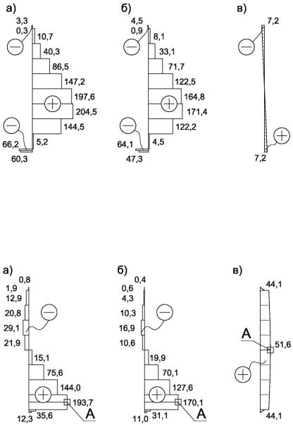
Fig. 8. Diagrams of normal stresses, MPa, for the second vertical row of FE:
a)values of the normal stresses for load combination No. 1;
b)for a combination of load cases № 2; c) for the rod scheme of combination № 1
a) |
|
b) |
|
c) |
Fig. 9. Diagrams of shear stresses, MPa, for the second vertical row of FE:
a)values of the shear stresses for load combination № 1;
b)for a combination of load cases № 2; c) for the rod scheme of combination № 1
25
Russian Journal of Building Construction and Architecture
Based on the diagrams of bending moments in Fig. 10, partial pinching relieves the beam in the middle of the span reducing the bending moment by 14.3 %.
kN/m
Road scheme
kN/m |
|
Fig. 10. Diagrams of the bending |
|
FE-model (one beam) |
|
|
moments My |
|
|
|
kN/m
FE-model (two beams)
kN/m kN/m of compression
Fig. 11 shows a diagram of the location of the bolts in the support rib prior to the calculations (Fig. 11, a) and following the analysis of the results of the numerical study (Fig. 11, b).
a) |
b) |
4 Bolts M24
Class 8.8
6 Bolts M20 |
4 Bolts M20 |
Class 5.8 |
Class 5.8 |
Fig. 11. Layout diagram of a bolted connection in a support node: a) prior to the research; b) based on research results
The tensile forces in the M20 bolts are distributed unevenly over the horizontal rows: for the first row N = 0 kN, for the second (middle) row N = 30 kN in each bolt and for the uppermost
26
Issue № 1 (49), 2021 |
ISSN 2542-0526 |
row, the tensile force in the bolt is N = 268 kN. Conventionally, it can be assumed that the rotation of the support node emerges around a line with zero bolt force (bottom row), and the forces in the second (middle) and extreme (upper) rows indicate a non-classical and nontriangular shape of the deformation diagram of the support rib during rotation. Most of the tensile force is applied to the top row of bolts. Two previously adopted M20 bolts of strength class 5.8 in the top row do not satisfy the condition of tensile strength. For the top row, it is essential to install 4 bolts М24 of strength class 8.8 or higher [19]. Each such bolt will have a maximum tensile force N = 134 kN.
Conclusions
1.As a result of the studies, pinching the beam was found to reduce the bending moment in the span by 14.3 %, the revealed redistribution of forces also decreases the deformation of the structure in the span. As the cross-section of double-support beams is selected based on two groups of limiting states precisely in the middle part of the span, a drop in the moment and deformations makes it possible to achieve an increase in material consumption indicators by selecting sections of steel I-beams with lower required geometric characteristics.
2.It has been established that beams with a gap tightly filled with mounting spacers and bolts tightened to the stop in the support section can be considered partially continuous mechanical systems. The properties of these systems call for further research to be carried out.
3.It has been proven that the moment from partial pinching in the support unit causes significant tensile stresses in the wall and reduces the load bearing capacity of the unit. The following constructive measures are set forth in order to strengthen the wall in the support compartment: increasing the wall thickness as well as the strength class of steel, welding the sheet for local reinforcement.
4.The above combination with asymmetric loading reduces the stress values in the elements of the support node.
5.The upper row of bolts in the support assembly was found to experience considerable tensile forces. Stretching can cause a loss of strength of the bolts if the section is taken for design reasons without considering the forces from partial pinching of the beam.
6.It has been confirmed that a complete analysis of the power operation of load-bearing steel beams is possible only if modern plate and / or three-dimensional FE models. The pivotal schematization of structural analysis does not enable one to completely identify the SS.
7.It is shown that the use of one-sided two-node connections in calculations in computer systems makes it possible to set the conditions for fixing a structure without explicitly modeling bolts and mounting gaskets.
27

Russian Journal of Building Construction and Architecture
References
1.Belostotskii A. M., Akimov P. A., Dmitriev D. S., Nagibovich A. I., Petryashev N. O., Petryashev S. O.
Raschetnoe issledovanie parametrov mekhanicheskoi bezopasnosti vysotnogo (404 metra) zhilogo kompleksa «One Tower» v delovom tsentre «Moskva-Siti» [Computational study of the mechanical safety parameters of the high-rise (404 meters) residential complex "One Tower" in the business center "Moscow-City"]. Academia. Arkhitektura i stroitel'stvo, 2019, no. 3, pp. 122—129.
2.Vardanyan G. S., Atarov N. M., Gorshkov A. A. Soprotivlenie materialov [Resistance of materials]. Moscow, INFRA-M Publ., 2003. 480 p.
3.Gallager R. Metod konechnykh elementov. Osnovy [The finite element method. The basics]. Moscow, Mir Publ., 1984. 428 p.
4.Zenkevich O., Morgan K. Konechnye elementy i approksimatsiya [Finite elements and approximation]. Moscow, Mir Publ., 1986. 318 p.
5.Ignat'ev A. V., Ignat'ev V. A., Gamzatova E. A. Analiz izgibaemykh plastinok s odnostoronnimi svyazyami po metodu konechnykh elementov v forme klassicheskogo smeshannogo metoda [Analysis of bent plates with one-way connections by the finite element method in the form of the classical mixed method]. Izv. vuzov. Stroitel'stvo, 2018, no. 8 (716), pp. 5—14.
6.Karpilovskii V. S., Kriksunov E. Z., Malyarenko A. A., Mikitarenko M. A., Perel'muter A. V., Perel'muter M. A. SCAD Office. Vychislitel'nyi kompleks SCAD [SCAD Office. SCAD computing complex]. Moscow, ACB Publ., 2007. 592 p.
7.Levenko V. F. O raschete sharnirno-sterzhnevykh sistem s odnostoronnimi svyazyami [On the calculation of hinge-rod systems with one-way connections]. Izv. vuzov. Stroitel'stvo i arkhitektura, 1971, no. 7, pp. 67—70.
8.Lyakhovich L. S., Perel'muter A. V., Slivker V. I. Rol' paradoksov v otsenke korrektnosti raschetnykh modelei [The role of paradoxes in evaluating the correctness of computational models]. Vestnik TGASU, 2013, no. 2, pp. 121—131.
9.Norri D., Friz Zh. de. Vvedenie v metod konechnykh elementov [Introduction to the finite element method]. Moscow, Mir Publ., 1981. 304 p.
10.Rabinovich I. M. Kurs stroitel'noi mekhaniki sterzhnevykh sistem. Ch. 1 [Course of structural mechanics of rod systems. Part 1]. Moscow, Gos. izd-vo str. lit-ry, 1950. 387 p.
11.Sventikov A. A., Kuznetsov D. N. Adaptatsiya rezul'tatov chislennogo metoda rascheta k normativnoi metodike proverki mestnoi ustoichivosti stenki stal'noi balki dvutavrovogo secheniya [Adaptation of the results of the numerical calculation method to the standard method of checking the local stability of the steel beam wall of the I-beam section]. Stroitel'naya mekhanika i konstruktsii, 2019, no. 1 (20), pp. 60—70.
12.Sventikov A. A., Kuznetsov D. N. Analiz vliyaniya reber zhestkosti na mestnuyu ustoichivost' stenki i ustoichivost' stal'noi ramy dvutavrovogo peremennogo po vysote secheniya [Analysis of the effect of stiffeners on the local stability of the wall and the stability of the steel frame of the I-beam variable height section].
Stroitel'naya mekhanika i konstruktsii, 2018, no. 1 (16), pp. 75—85.
13.Skladnev N. N. Optimal'noe proektirovanie konstruktsii i ekonomiya material'nykh resursov [Optimal design of structures and saving of material resources]. Prilozhenie k zhurnalu «Stroitel'naya mekhanika i raschet sooruzhenii», 1982, no. 6, pp. 17—21.
28
Issue № 1 (49), 2021 |
ISSN 2542-0526 |
14.Teplykh A. V. Primenenie obolochechnykh i ob"emnykh elementov pri raschetakh stroitel'nykh stal'nykh konstruktsii v programmakh SCAD i Nastran c uchetom geometricheskoi i fizicheskoi nelineinosti [Application of shell and bulk elements in the calculations of building steel structures in the SCAD and Nastran programs, taking into account geometric and physical nonlinearity]. Inzhenerno-stroitel'nyi zhurnal, 2011, no. 3, pp. 4—20.
15.Troitskii P. N., Levitanskii I. V. Opornye soedineniya razreznykh balok na vertikal'nykh nakladkakh, privarivaemykh k stenke balki (uzly UNS) [Support joints of split beams on vertical linings welded to the beam wall (UNS units)]. Informatsionnyi referativnyi sbornik, 1970, no. 4 (24), pp. 2—68.
16.Tusnin A. R., Prokich M. Rabota simmetrichnykh dvutavrovykh sechenii pri razvitii plasticheskikh deformatsii i deistvii izgibayushchego momenta i bimomenta [Operation of symmetric I-sections under the development of plastic deformations and the action of bending moment and bimoment]. Inzhenerno-stroitel'nyi zhurnal, 2014, no. 5, pp. 44—53.
17.Tusnina V. M., Kolyago A. A. K voprosu deistvitel'noi raboty podatlivykh uzlov stal'nykh karkasov mnogoetazhnykh zdanii [On the question of the actual operation of the malleable units of steel frames of multistorey buildings]. Promyshlennoe i grazhdanskoe stroitel'stvo, 2018, no. 2, pp. 28—34.
18.Tusnina O. A., Danilov A. I. Zhestkost' ramnykh uzlov sopryazheniya rigelya s kolonnoi korobchatogo secheniya [Rigidity of the frame units of the coupling of the crossbar with the column of the box section].
Inzhenerno-stroitel'nyi zhurnal, 2016, no. 4 (64), pp. 40—51.
19.Perelmuter A. V., Veriuzhska T. Y. Optimization of the overload-protection degree. Engineering Optimization IV. London, Taylor & Francis Group, 2014. P. 529—532.
20.Sventikov A., Kuznetsov D. Evaluation of the Influence of the Stiffeners on the Overall Stability of the Va- riable-Rigidity Steel Frame Using FEM. International science conference Far East Con 2018: Materials Science and construction, 2018. Part 2. P. 1—6—463 022091. doi: 10.1088/1757—899X/463/2/022091.
21.Trubina D., Abdulaev D., Pichugin E., Rybokov V. Geometric nonlinearity of the thin-walled profile under transverse bending. Applied Mechanics and Materials, 2014, vol. 633—634, pp. 1133—1139.
22.Volkov A. A., Vasilkin A. A. Оptimal design of the steel structure by the sequence of partial optimization. Procedia Engineering, 2016, vol. 153, pp. 850—855.
23.Zienkiewicz O., Irons B., Scott F. C., Campbell J. S. Three-Dimensional Stress Analysis. Proc. Of Symp. High Speed Computing of Elastic Structures, Univ. of Liege, Belgium, 1970. Part 1. P. 413—432.
29

Russian Journal of Building Construction and Architecture
DOI 10.36622/VSTU.2021.49.1.003
UDC 691.32
L. R. Mailyan 1, S. A. Stel'makh 2, E. M. Shcherban 3, M. P. Nazhuev 4
SETTING A DIAGRAM APPROACH TO CALCULATING VIBRATED, CENTRIFUGED AND VIBROCENTRIFUGED REINFORCED CONCRETE COLUMNS WITH A VARIATROPIC STRUCTURE
Don State Technical University 1, 2, 3, 4
Russia, Rostov-on-Don
1 D. Sc. in Engineering, Prof. of the Dept. of Dept. of Highways
2 PhD in Engineering, Assoc. Prof of the Dept. of Engineering Geology, Bases and Foundations, e-mail: sergej.stelmax@mail.ru
3 PhD in Engineering, Assoc. Prof of the Dept. of Engineering Geology, Bases and Foundations, e-mail: au-geen@mail.ru
4 Lecturer of the Dept. of Technological Engineering and Expertise in the Construction Industry, e-mail: nazhuev17@mail.ru
Statement of the problem. Reinforced concrete elements are typically manufactured according to three basic technologies - vibration, centrifugation and vibrocentrifugation. However, all the basic calculated dependencies for determining their bearing capacity were derived using the main postulate, i.e., the constancy and equality of the characteristics of concrete over the cross section, which is implemented only in vibrated columns.
Results. Within the framework of the diagrammatic approach, iterative, approximate and simplified methods of calculating the bearing capacity of reinforced concrete vibrated, centrifuged and vibrocentrifuged columns are proposed.
Conclusions. The calculation according to the diagrammatic approach showed a significantly better convergence with the experimental data than that using the method of norms, and also performs better when using differential characteristics of concrete than when employing integral and particularly standard characteristics of concrete.
Keywords: diagram approach, iterative calculation method, approximate calculation method, simplified calculation method, load-bearing capacity, vibrated concrete columns, centrifuged columns, vibrocentrifuged columns.
Introduction. The relevance of the study is due to the increasing volumes of construction call for new technological, structural and design solutions for reinforced concrete elements. A reduction in the material consumption of reinforced concrete structures is inextricably linked with the improvement of structural forms and employment of elements of thin-walled sections
© Mailyan L. R., Stel’makh S. А., Schcherban Е. М., Nazhuev М. P., 2021
30