

[AK4493]
■ Short Delay Slow Roll-Off Filter Characteristics
Short Delay Slow Roll-Off Filter Characteristics (fs = 44.1kHz)
(Ta = -40 ~ 85 C; VDDL/R = 4.75 5.25V, AVDD = TVDD = 1.7 3.6V, DVDD = 1.7 ~ 1.98V; Normal Speed Mode; DEM = OFF; SD bit = “1” or SD pin = “H”, SLOW bit = “1” or SLOW pin = “H”, SSLOW bit = “0” or SSLOW pin = “L”)
Parameter |
|
|
Symbol |
Min. |
Typ. |
Max. |
Unit |
Digital Filter |
|
|
|
|
|
|
|
Frequency Response |
|
0.01dB |
- |
0 |
- |
8.0 |
kHz |
(Note 26) |
|
6.0dB |
- |
- |
21.0 |
- |
kHz |
Passband |
|
(Note 29) |
PB |
0 |
- |
8.0 |
kHz |
Stopband |
|
(Note 29) |
SB |
39.2 |
- |
- |
kHz |
Passband Ripple |
|
(Note 28) |
PR |
- |
- |
0.007 |
dB |
Stopband Attenuation |
|
(Note 26) |
SA |
92 |
- |
- |
dB |
Group Delay |
(Note 29) |
GD |
- |
5.0 |
- |
1/fs |
|
Digital Filter + SCF |
|
(Note 26) |
|
|
|
|
|
Frequency Response: 0 20.0kHz |
|
-5.0 |
- |
+0.1 |
dB |
||
Short Delay Slow Roll-Off Filter Characteristics (fs = 96kHz)
(Ta = -40 ~ 85 C; VDDL/R = 4.75 5.25V, AVDD = TVDD = 1.7 3.6V, DVDD = 1.7 ~ 1.98V; Double Speed Mode; DEM = OFF; SD bit = “1” or SD pin = “H”, SLOW bit = “1” or SLOW pin = “H”, SSLOW bit = “0” or SSLOW pin = “L”)
Parameter |
|
|
Symbol |
Min. |
Typ. |
Max. |
Unit |
Digital Filter |
|
|
|
|
|
|
|
Frequency Response |
|
0.01dB |
- |
0 |
- |
17.6 |
kHz |
(Note 26) |
|
6.0dB |
- |
- |
45.6 |
- |
kHz |
Passband |
|
(Note 29) |
PB |
0 |
- |
17.6 |
kHz |
Stopband |
|
(Note 29) |
SB |
85.4 |
- |
- |
kHz |
Passband Ripple |
|
(Note 28) |
PR |
- |
- |
0.007 |
dB |
Stopband Attenuation |
|
(Note 26) |
SA |
100 |
- |
- |
dB |
Group Delay |
(Note 29) |
GD |
- |
5.0 |
- |
1/fs |
|
Digital Filter + SCF |
|
(Note 26) |
|
|
|
|
|
Frequency Response: 0 40.0kHz |
|
-3.8 |
- |
+0.1 |
dB |
||
Short Delay Slow Roll-Off Filter Characteristics (fs = 192kHz)
(Ta = -40 ~ 85 C; VDDL/R = 4.75 5.25V, AVDD = TVDD = 1.7 3.6V, DVDD = 1.7 ~ 1.98V;
Quad Speed Mode; DEM = OFF; SD bit = “1” or SD pin = “H”, SLOW bit = “1” or SLOW pin = “H”, SSLOW bit = “0” or SSLOW pin = “L”)
Parameter |
|
|
Symbol |
Min. |
Typ. |
Max. |
Unit |
Digital Filter |
|
|
|
|
|
|
|
Frequency Response |
|
0.01dB |
- |
0 |
- |
35.2 |
kHz |
(Note 26) |
|
6.0dB |
- |
- |
91.2 |
- |
kHz |
Passband |
|
(Note 29) |
PB |
0 |
- |
35.2 |
kHz |
Stopband |
|
(Note 29) |
SB |
170.7 |
- |
- |
kHz |
Passband Ripple |
|
(Note 28) |
PR |
- |
- |
0.007 |
dB |
Stopband Attenuation |
|
(Note 26) |
SA |
100 |
- |
- |
dB |
Group Delay |
(Note 29) |
GD |
- |
5.0 |
- |
1/fs |
|
Digital Filter + SCF |
|
(Note 26) |
|
|
|
|
|
Frequency Response: 0 80.0kHz |
|
-5.0 |
- |
+0.1 |
dB |
||
Note 29. The passband and stopband frequencies scale with fs.
For example, PB = 0.1836 fs (@ 0.01dB), SB = 0.8866 fs.
017012230-E-00 |
2017/12 |
|
- 21 - |
[AK4493]
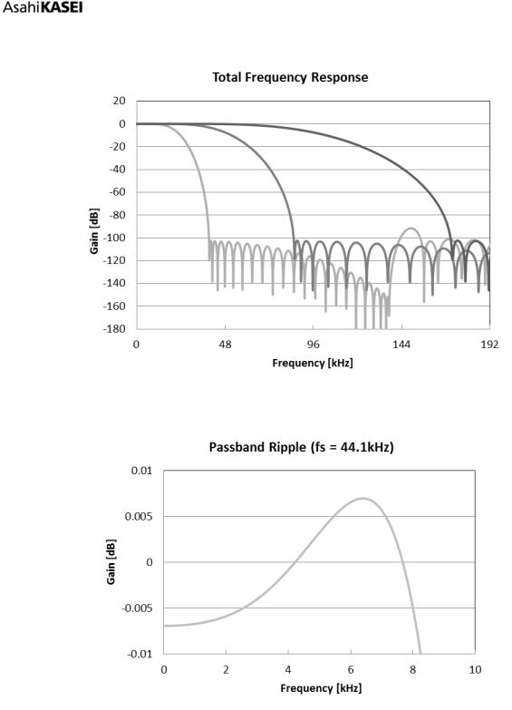
Figure 9. Short Delay Slow Roll-off Filter Frequency Response
Figure 10. Short Delay Slow Roll-off Filter Passband Ripple
017012230-E-00 |
2017/12 |
|
- 22 - |

[AK4493]
■ Low Dispersion Short Delay Filter Characteristics
Low Dispersion Short Delay Filter Characteristics (fs = 44.1kHz)
(Ta = -40 ~ 85 C; VDDL/R = 4.75 5.25V, AVDD = TVDD = 1.7 3.6V, DVDD = 1.7 ~ 1.98V; Normal Speed Mode; DEM = OFF; SD bit = “1” or SD pin = “H”, SLOW bit = “X” or SLOW pin = “X”, SSLOW bit = “1” or SSLOW pin = “H”)
Parameter |
|
|
Symbol |
Min. |
Typ. |
Max. |
Unit |
Digital Filter |
|
|
|
|
|
|
|
Frequency Response |
|
0.05dB |
- |
0 |
- |
18.4 |
kHz |
(Note 26) |
|
6.0dB |
- |
- |
22.05 |
- |
kHz |
Passband |
(Note 32) |
PB |
0 |
- |
18.4 |
kHz |
|
Stopband |
(Note 32) |
SB |
25.7 |
- |
- |
kHz |
|
Passband Ripple |
|
(Note 28) |
PR |
- |
- |
0.05 |
dB |
Stopband Attenuation |
|
(Note 26) |
SA |
80 |
- |
- |
dB |
Group Delay |
(Note 29) |
GD |
- |
10.0 |
- |
1/fs |
|
Group Delay Distortion |
|
|
GD |
- |
±0.035 |
- |
1/fs |
Digital Filter + SCF |
|
(Note 26) |
|
|
|
|
|
Frequency Response: 0 20.0kHz |
|
-0.8 |
- |
+0.1 |
dB |
||
Low Dispersion Short Delay Filter Characteristics (fs = 96kHz)
(Ta = -40 ~ 85 C; VDDL/R = 4.75 5.25V, AVDD = TVDD = 1.7 3.6V, DVDD = 1.7 ~ 1.98V; Double Speed Mode; DEM = OFF; SD bit = “1” or SD pin = “H”, SLOW bit = “X” or SLOW pin = “X”, SSLOW bit = “1” or SSLOW pin = “H”)
Parameter |
|
|
Symbol |
Min. |
Typ. |
Max. |
Unit |
Digital Filter |
|
|
|
|
|
|
|
Frequency Response |
|
0.05dB |
- |
0 |
- |
40.1 |
kHz |
(Note 26) |
|
6.0dB |
- |
- |
48.0 |
- |
kHz |
Passband |
(Note 32) |
PB |
0 |
- |
40.1 |
kHz |
|
Stopband |
(Note 32) |
SB |
55.9 |
- |
- |
kHz |
|
Passband Ripple |
|
(Note 28) |
PR |
- |
- |
0.05 |
dB |
Stopband Attenuation |
|
(Note 26) |
SA |
80 |
- |
- |
dB |
Group Delay |
(Note 29) |
GD |
- |
10.0 |
- |
1/fs |
|
Group Delay Distortion |
|
|
GD |
- |
±0.035 |
- |
1/fs |
Digital Filter + SCF |
|
(Note 26) |
|
|
|
|
|
Frequency Response: 0 40.0kHz |
|
-0.6 |
- |
+0.1 |
dB |
||
Low Dispersion Short Delay Filter Characteristics (fs = 192kHz)
(Ta = -40 ~ 85 C; VDDL/R = 4.75 5.25V, AVDD = TVDD = 1.7 3.6V, DVDD = 1.7 ~ 1.98V;
Quad Speed Mode; DEM = OFF; SD bit = “1” or SD pin = “H”, SLOW bit = “X” or SLOW pin = “X”, SSLOW bit = “1” or SSLOW pin = “H”)
Parameter |
|
|
Symbol |
|
Min. |
Typ. |
Max. |
Unit |
Digital Filter |
|
|
|
|
|
|
|
|
Frequency Response |
|
0.05dB |
- |
|
0 |
- |
80.2 |
kHz |
(Note 26) |
|
6.0dB |
- |
|
- |
98.0 |
- |
kHz |
Passband |
(Note 32) |
PB |
|
0 |
- |
80.2 |
kHz |
|
Stopband |
(Note 32) |
SB |
|
111.8 |
- |
- |
kHz |
|
Passband Ripple |
|
(Note 28) |
PR |
|
- |
- |
0.05 |
dB |
Stopband Attenuation |
|
(Note 26) |
SA |
|
80 |
- |
- |
dB |
Group Delay |
(Note 29) |
GD |
|
- |
10.0 |
- |
1/fs |
|
Group Delay Distortion |
|
|
GD |
|
- |
±0.035 |
- |
1/fs |
Digital Filter + SCF |
|
(Note 26) |
|
|
|
|
|
|
Frequency Response: 0 80.0kHz |
|
|
-2.0 |
- |
+0.1 |
dB |
||
Note 320. The passband and stopband frequencies scale with fs. |
|
|
|
|||||
For example, PB = 0.418 fs (@ 0.05dB), SB = 0.582 fs. |
|
|
||||||
017012230-E-00 |
|
|
|
|
|
|
|
2017/12 |
|
|
|
- 23 - |
|
|
|
|
|
[AK4493]
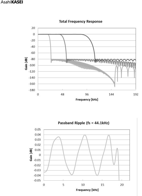
Figure 11. Low Dispersion Short Delay Filter Frequency Response
Figure 12. Low Dispersion Short Delay Filter Passband Ripple
017012230-E-00 |
2017/12 |
|
- 24 - |