

[AK4493]
■ Soft Mute Operation (PCM, DSD, EXDF)
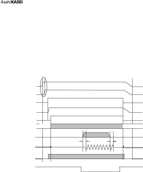
The soft mute operation is performed at digital domain. When setting the SMUTE pin to “H” or SMUTE bit to “1”, the output signal is attenuated by during ATT_DATA ATT transition time from the current ATT level.
When setting back the SMUTE pin to “L” or SMUTE bit to “0”, the mute is cancelled and the output attenuation gradually changes to the ATT level during ATT_DATA ATT transition time (Refer to Table 30 for ATT). If the soft mute is cancelled before attenuating after starting the operation, the attenuation is discontinued and returned to ATT level by the same cycle. The soft mute is effective for changing the signal source without stopping the signal transmission.
SMUTE pin or
SMUTE bit
(1) |
(1) |
ATT_Level |
|
Attenuation |
(3) |
|
|
- |
(2)GD |
(2)GD |
|
|
||
AOUTL/R |
|
|
|
|
|
(4) |
|
DZFL/R pin |
|
8192/fs |
|
|
|
|
Note:
(1)ATT_DATA ATT transition time. For example, this time is 4080LRCK cycles at ATT_DATA = 255 in PCM Normal Speed Mode.
(2)The analog output corresponding to the digital input has group delay (GD).
(3)If the soft mute is cancelled before attenuating after starting the operation, the attenuation is discontinued and returned to ATT level by the same cycle.
(4)When the input data for each channel is continuously zeros for 8192 LRCK cycles, the DZFL/R pin for each channel goes to “H”. The DZFL/R pin immediately returns to “L” if the input data is not zero.
Figure 57. Soft Mute Function
017012230-E-00 |
2017/12 |
|
- 71 - |

[AK4493]
■ LDO
When TVDD = 3.0 ~ 3.6V, the power for digital core circuit (DVDD) is supplied by the internal LDO by setting the LDOE pin to “H”. Table 45 shows the DVDD pin statuses with the PDN and LDOE pins setting. The internal LDO is powered up by setting the PDN pin from “L” to “H” (power-down release) and it starts supplying 1.8V DVDD. Connect a 1uF (±50%) capacitor to the DVDD pin when using the LDO. It takes 0.1ms (max.) to power-up the internal LDO.
Table 45. LDO Select Mode (* = Do not care)
PDN |
LDOE |
TVDD |
DVDD |
|
|
|
|
|
|
* |
L |
1.7~3.6V |
LDO OFF: Supply 1.7 ~ 1.98V to the DVDD pin |
|
|
externally |
|||
|
|
|
||
|
|
|
|
|
L |
H |
3.0~3.6V |
500 ohm Pull-down |
|
|
|
|
|
|
H |
H |
3.0~3.6V |
LDO ON: LDO outputs 1.8V. |
|
(Do not connect DVDD with other device loads) |
||||
|
|
|
||
|
|
|
|
The AK4493 has error detect function, as shown in Table 46 for LDO operation (LDOE pin = “H”). The internal LDO will be powered down and stop supplying the power to the digital core when an error is detected. In this case, the analog signal output and the PDA pin becomes Hi-z state (In I2C mode, ACK is not output). The AK4493 must be reset by setting the PDN pin = “L” → “H” to recover from the error detection status.
|
|
Table 46. Error Detection |
No |
Error Detection |
Error Detection Conditions |
|
|
The AK4493 detects an error when the output voltage of the |
1 |
LDO Overvoltage Detection |
LDO pin exceeds overvoltage threshold. |
|
|
Threshold: 2.35V (typ), min: 2.2V, max: 2.5V |
|
|
|
|
|
The AK4493 detects an error when the current flows PMOS |
2 |
LDO Overcurrent Detection |
from LDO output exceeds overcurrent threshold. |
|
|
Threshold: 50mA (typ), min: 40mA, max: 110mA |
|
|
|
■ Shutdown Switch
A shutdown switch is placed between the DVDD pin and the internal VDD for the digital core to prevent SIDD leak of DVDD digital power supply.
When using LDO (LDOE pin = “H”), the shutdown switch is ON after counting by internal oscillator following a power-down release (PDN pin “L” → “H”). It takes 2ms (max.) for the shutdown switch power-up.
When not using LDO (LDOE pin = “L”), the shutdown switch is ON immediately after a power-down release (PDN pin “L” → “H”). It takes 1us (max.) for the shutdown switch power-up.
■ Analog Output Overcurrent Protection
Analog output pins AOUTLP/LN and AOUTRP/RN have channel independent overcurrent protection. When a current that exceeds 85mA (typ.) is output from analog output pins, this function limits the output not to exceed 85mA. This overcurrent protection is invalid if the PDN pin = “L”, PW bit = “0” or MCLK is stopped.
017012230-E-00 |
2017/12 |
|
- 72 - |
[AK4493]
■ Power Up/Down Function
The AK4493 is powered down when the PDN pin is “L”. In power-down state, all circuits stop operation and initialized, and the analog output becomes floating (Hi-z) state. The PDN pin must held “L” for more than 150ns for a certain reset after all power supplies are on. There is a possibility of malfunctions with the “L” pulse less than 150ns. Power-down is released by setting the PDN pin to “H” from “L”. In this time Bias generating circuit and LDO (if LDOE pin = “H”) are powered up and the analog output becomes floating (Hi-z) state until all clocks are input.
[1] Pin Control Mode (PSN pin = “H”)
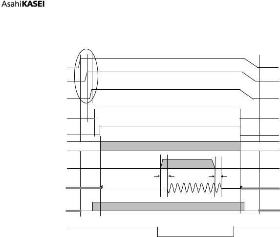
All circuits will be powered up by inputting MCLK, LRCK and BICK clocks after the PDN pin = “H”. The analog circuit starts operation just after supplying all necessary clocks (MCLK, LRCK and BICK) and the digital circuit starts operation in about 4/fs after the clock supply. Figure 58 shows system timing example of power down/up when using the internal LDO (LDOE pin “H”).
Power |
|
|
|
|
|
(TVDD,AVDD,VDDL/R) |
|
|
|
|
|
|
(8) |
|
|
|
|
Analog Reference |
|
|
|
|
|
(VREFHL,VREFHR) |
|
|
|
|
|
PDN pin |
(1) |
|
|
|
|
DVDD pin |
|
|
|
|
|
Internal PDN |
(2) |
|
|
|
|
Internal State |
Reset |
Normal Operation (DAC ) |
|
Reset |
|
|
|
||||
DAC In |
|
“0”data |
|
“0”data |
|
(Digital) |
|
|
|
||
|
|
|
|
||
|
|
|
|
|
|
|
|
GD |
(3) |
GD |
|
|
|
|
|
||
DAC Out |
(4) Hi-Z (5) |
|
|
(5) |
Hi-Z (4) |
(Analog) |
|
|
|
|
|
Clock In |
(7) |
|
|
|
(7) |
MCLK,LRCK,BICK |
|
|
|
|
|
External |
|
|
|
|
|
Mute |
(6) |
Mute ON |
|
|
Mute ON |
Notes:
(1)The PDN pin must be “L” when start supplying AVDD, TVDD and VDDL/R. It must be held “L” for more than 150ns after AVDD, TVDD and VDDL/R are powered up.
(2)Internal LDO is powered up after the PDN pin = “H” if the LDOE pin = “H”. The internal circuit will start operation after the shutdown switch is ON (max. 2ms) following the internal oscillator count up.
(3)The analog output corresponding to the digital input has group delay (GD).
(4)Analog outputs are floating (Hi-Z) in power down mode.
(5)Click noise occurs on an edge of PDN signal. This noise is output even if “0” data is input.
(6)Mute the analog output externally if click noise (5) adversely affect system performance.
(7)Do not input clocks (MCLK, BICK and LRCK) until after the power supplies are turned on.
(8)VREFH/L must be powered up after or at the same time of VDDL/R.
Figure 58. Power-down/up Sequence Example (Pin Control Mode, LDOE pin = “H”)
017012230-E-00 |
2017/12 |
|
- 73 - |
[AK4493]
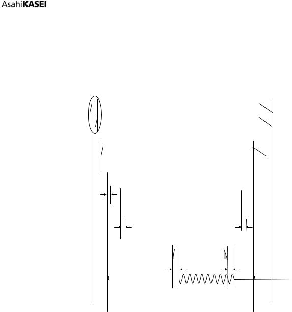
The timing example when not using the internal LDO (LDOE pin = “L”) is shown in Figure 59. When the LDOE pin = “L”, TVDD must be powered up before or at the same time of the DVDD.
Power |
|
|
|
|
|
|
|
|
(TVDD) |
|
|
(8) |
|
|
|
|
|
|
|
|
|
|
|
|
|
|
Power |
|
|
|
|
|
|
|
|
(DVDD,AVDD,VDDL/R) |
|
|
|
|
|
|
|
|
Analog Reference |
|
|
|
|
|
|
|
|
(VREFHL/R) |
|
|
|
|
|
|
|
|
PDN pin |
|
(1) |
|
|
|
|
|
|
|
|
|
|
|
|
|
|
|
Internal PDN |
|
|
(2) |
|
|
|
|
|
Internal State |
|
Reset |
|
Normal Operation (DAC ) |
|
Reset |
|
|
|
|
|
|
|
||||
DAC In |
|
|
|
“0”data |
|
“0”data |
|
|
(Digital) |
|
|
|
|
|
|
||
|
|
|
|
|
|
|
||
|
|
|
|
|
|
|
|
|
|
|
|
|
GD |
(3) |
GD |
|
|
|
|
|
|
|
|
|
||
DAC Out |
(4) |
Hi-Z |
(5) |
|
|
(5) |
Hi-Z |
(4) |
|
|
|
||||||
(Analog) |
|
|
|
|
|
|
|
|
Clock In |
(7) |
|
|
|
|
|
|
(7) |
MCLK,LRCK,BICK |
|
|
|
|
|
|
|
|
|
|
|
|
|
|
|
|
|
External |
|
|
|
|
|
|
|
|
Mute |
|
|
(6) |
Mute ON |
|
|
Mute ON |
|
Notes:
(1)The PDN pin must be “L” when start supplying AVDD, TVDD, DVDD and VDDL/R. It must be held “L” for more than 150ns after AVDD, TVDD, DVDD and VDDL/R are powered up.
(2)Internal shutdown switch is on after power-up if the LDOE pin = “L”. The internal circuit will start operation in 1us (max.) after the shutdown switch is ON.
(3)The analog output corresponding to the digital input has group delay (GD).
(4)Analog outputs are floating (Hi-Z) in power down mode.
(5)Click noise occurs on an edge of PDN signal. This noise is output even if “0” data is input.
(6)Mute the analog output externally if click noise (5) adversely affect system performance.
(7)Do not input clocks (MCLK, BICK and LRCK) until after the power supplies are turned on.
(8)TVDD must be powered up before or at the same time of DVDD. VREFH/L must be powered up after or at the same time of VDDL/R.
(9)TVDD must be powered down after or at the same time of DVDD. Power-down sequences of other power supplies are not critical.
Figure 59. Power-down/up Sequence Example (Pin Control Mode, LDOE pin = “L”)
017012230-E-00 |
2017/12 |
|
- 74 - |
[AK4493]
(b) Register Control Mode (PSN pin = “L”)
Figure 60 shows system timing example of power down/up when using the internal LDO (LDOE pin =
“H”).
Register access becomes available and internal LDO is powered up after setting the PDN pin = “H”. The analog circuit starts operation by supplying necessary clocks (MCLK, LRCK and BICK for PCM mode, MCLK and DCLK for DSD mode, MCLK, BCK and WCK for EXDF mode) and the clock divider is powered up about after 4/fs. In this time, the analog output pins output analog common voltages (VCML, VCMR). Then the AK4493 transitions to normal operation by setting RSTN bit = “1”.
Power |
|
|
|
|
|
|
|
|
|
|
|
|
|
|
|
|
|
|
|
|
|
|
|
|
|
|
|
|
|
|||
|
|
|
|
|
|
|
|
|
|
|
|
|
|
|
|
|
|
|
|
|
|
|
|
|
|
|
|
|
||||
(TVDD,AVDD,VDDL/R) |
|
|
|
(11) |
|
|
|
|
|
|
|
|
|
|
|
|
|
|
|
|
|
|
||||||||||
Analog Reference |
|
|
|
|
|
|
|
|
|
|
|
|
|
|
|
|
|
|
|
|
|
|
|
|
|
|
|
|
|
|
||
|
|
|
|
|
|
|
|
|
|
|
|
|
|
|
|
|
|
|
|
|
|
|
|
|
|
|
|
|
||||
(VREFHL/R) |
|
|
|
|
|
|
|
|
|
|
|
|
|
|
|
|
|
|
|
|
|
|
|
|
|
|
|
|
|
|
||
PDN pin |
|
|
|
(1) |
|
|
|
|
|
|
|
|
|
|
|
|
|
|
|
|
|
|
|
|
|
|
|
|||||
|
|
|
|
|
|
|
|
|
|
|
|
|
|
|
|
|
|
|
|
|
|
|
|
|
|
|||||||
|
|
|
|
|
|
|
|
|
|
|
|
|
|
|
|
|
|
|
|
|
|
|
|
|
|
|
|
|
|
|
|
|
DVDD pin |
|
|
|
|
|
|
|
|
|
|
|
|
|
|
|
|
|
|
|
|
|
|
|
|
|
|
|
|
|
|||
|
|
|
|
|
|
|
|
|
|
|
|
|
|
|
|
|
|
|
|
|
|
|
|
|
|
|
|
|
||||
|
|
|
|
|
|
|
|
|
|
|
|
|
|
|
|
|
|
|
|
|
|
|
|
|
|
|
|
|
|
|||
Internal PDN |
|
|
|
(2) |
|
|
|
|
|
|
|
|
|
|
|
|
|
|
|
|
|
|
|
|
|
|||||||
|
|
|
|
|
|
|
|
|
|
|
|
|
|
|
|
|
|
|
|
|
|
|
|
|||||||||
|
|
|
|
|
|
|
|
|
|
|
|
|
|
|
|
|
|
|
|
|
|
|
|
|
|
|
|
|
|
|
|
|
RSTN bit |
|
|
|
|
|
|
|
|
|
|
|
|
|
|
|
|
|
|
|
|
|
|
|
|
|
|
|
|
|
|||
|
|
|
|
|
|
|
|
|
|
|
|
|
|
|
|
|
|
|
|
|
|
|
|
|
|
|
|
|
||||
|
|
|
|
|
|
|
|
|
|
|
|
|
|
|
|
|
|
|
|
|
|
|
|
|
|
|
|
|
|
|
|
|
|
|
|
|
|
|
|
|
|
|
|
|
|
(8) |
|
|
|
|
|
|
|
|
|
|
|
|
|
|
|
|
|
|
|
Internal State |
|
|
|
|
|
|
|
|
|
|
|
|
|
|
|
|
|
|
|
|
|
|
|
|
|
|
|
|
|
|
|
|
|
|
|
|
|
Reset |
|
|
|
|
|
Normal Operation |
|
|
|
|
Reset |
|
|
|
|||||||||||||
(Resister |
|
|
|
|
|
|
|
|
|
|
|
|
|
|
|
|
||||||||||||||||
(Clock devider) |
|
|
|
|
|
|
|
|
|
|
|
|
|
|
|
|
|
|
|
|
|
|
|
|
|
|
|
|
|
|
||
|
|
|
|
|
|
|
|
|
|
|
|
|
|
|
|
|
(9) |
|
|
|
|
(9) |
|
|
|
|
|
|
|
|
|
|
Internal State |
|
|
|
|
|
|
|
|
|
|
|
|
|
|
|
|
|
|
|
|
|
|
|
|
|
|
|
|
|
|
|
|
|
|
|
|
|
|
|
|
Reset |
|
|
|
|
|
Normal Operation |
|
|
|
|
Reset |
|
|
|
||||||||||
(Digital Core) |
|
|
|
|
|
|
|
|
|
|
|
|
|
|
|
|
|
|
|
|||||||||||||
DAC In |
|
|
|
|
|
|
|
|
|
|
|
|
|
|
|
“0”data |
|
|
“0”data |
|
|
|
|
|
|
|
|
|||||
|
|
|
|
|
|
|
|
|
|
|
|
|
|
|
|
|
|
|
|
|
|
|
|
|||||||||
(Digital) |
|
|
|
|
|
|
|
|
|
|
|
|
|
|
|
|
|
|
|
|
|
|
|
|
|
|||||||
|
|
|
|
|
|
|
|
|
|
|
|
|
|
|
|
|
|
|
|
|
GD (3) |
|
GD |
|
|
|
|
|
|
|
|
|
DAC Out |
|
|
(4) |
|
Hi-Z |
(5) |
|
|
|
|
|
|
|
(5) |
|
Hi-Z |
(4) |
|
||||||||||||||
|
|
|
|
|
|
|
|
|
|
|
|
|
|
|
|
|
|
|
|
|
|
|
|
|
|
|
|
|
|
|
|
|
(Analog) |
|
|
|
|
|
|
|
|
|
|
|
|
|
|
|
|
|
|
|
|
|
|
|
|
|
|
|
|
|
|||
Clock In |
(10) |
|
|
|
|
|
|
|
|
|
|
|
|
|
|
|
|
|
|
|
|
|
|
|
|
|
(10) |
|
||||
|
|
|
|
|
|
|
|
|
|
|
|
|
|
|
|
|
|
|
|
|
|
|
|
|
|
|||||||
MCLK,LRCK,BICK |
|
|
|
|
|
|
|
|
|
|
|
|
|
|
|
|
|
|
|
|
|
|
|
|
|
|
|
|
|
|
||
DZFL/R |
|
|
|
|
|
|
|
|
|
|
|
|
|
|
|
|
|
|
|
|
|
|
|
(7) |
|
|
|
|
|
|
||
|
|
|
|
|
|
|
|
|
|
|
|
|
|
|
|
|
|
|
|
|
|
|
|
|
|
|
||||||
|
|
|
|
|
|
|
|
|
|
|
|
|
|
|
|
|
|
|
|
|
|
|
|
|
|
|
|
|
||||
External |
|
|
|
|
|
|
|
|
|
|
|
|
|
|
|
|
|
|
|
|
|
|
|
|
|
|
|
|
|
|
||
|
|
|
|
|
|
|
|
|
|
(6) |
|
|
|
|
|
|
|
|
|
|
|
|
|
|
|
|
|
|
||||
Mute |
|
|
|
|
|
|
|
|
|
|
|
Mute ON |
|
|
|
|
|
|
|
Mute ON |
|
|
||||||||||
Notes:
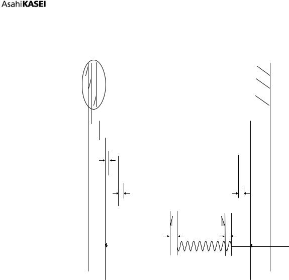
(1)The PDN pin must be “L” when start supplying AVDD, TVDD and VDDL/R. It must be held “L” for more than 150ns after AVDD, TVDD and VDDL/R are powered up.
(2)Internal shutdown switch is on after power-up if the LDOE pin = “L”. The internal circuit will start operation in 1us (max.) after the shutdown switch is ON.
(3)The analog output corresponding to the digital input has group delay (GD).
(4)Analog outputs are floating (Hi-Z) in power down mode.
(5)Click noise occurs on an edge of PDN signal. This noise is output even if “0” data is input.
(6)Mute the analog output externally if click noise (5) adversely affect system performance.
(7)The DZFL/R pin is “L” in power-down mode (PDN pin = “L”).
(8)The clock divider is powered up in about 4/fs after the internal PDN is released.
(9)It takes 3~4/fs until a reset instruction is valid when writing RSTN bit to “0” and it takes 2~3/fs when releasing the reset.
(10)Do not input clocks (MCLK, BICK and LRCK) during power down state.
(11)TVDD must be powered up before or at the same time of DVDD. VREFH/L must be powered up after or at the same time of VDDL/R.
017012230-E-00 |
2017/12 |
|
- 75 - |
[AK4493]
Figure 60. Power-down/up Sequence Example (Register Control Mode, LDOE pin = “H”)
The system timing example of power up/down when not using LDO (LODE pin = “L”) is shown in Figure 61. When the LDOE pin = “L”, TVDD must be powered up before or at the same time of DVDD.
Power |
|
|
|
|
|
|
|
|
|
|
|
|
|
|
|
|
|
|
|
|
|
|
|
|
|
|
|
|
|
(TVDD) |
|
|
|
|
|
|
|
|
|
(11) |
|
|
|
|
|
|
|
|
|
|
|
|
|
|
|
|
|
||
Power |
|
|
|
|
|
|
|
|
|
|
|
|
|
|
|
|
|
|
|
|
|
|
|
|
|
|
|
|
|
|
|
|
|
|
|
|
|
|
|
|
|
|
|
|
|
|
|
|
|
|
|
|
|
|
|
|
|
|
|
(DVDD,AVDD,VDDL/R) |
|
|
|
|
|
|
|
|
|
|
|
|
|
|
|
|
|
|
|
|
|
|
|
|
|
|
|||
|
|
|
|
|
|
|
|
|
|
|
|
|
|
|
|
|
|
|
|
|
|
|
|
|
|
|
|
|
|
Analog Reference |
|
|
|
|
|
|
|
|
|
|
|
|
|
|
|
|
|
|
|
|
|
|
|
|
|
|
|
|
|
|
|
|
|
|
|
|
|
|
|
|
|
|
|
|
|
|
|
|
|
|
|
|
|
|
|
|
|
|
|
(VREFHL/R) |
|
|
|
|
|
|
|
|
|
|
|
|
|
|
|
|
|
|
|
|
|
|
|
|
|
|
|
|
|
PDN pin |
|
|
|
(1) |
|
|
|
|
|
|
|
|
|
|
|
|
|
|
|
|
|
|
|
|
|
|
|||
|
|
|
|
|
|
|
|
|
|
|
|
|
|
|
|
|
|
|
|
|
|
|
|
|
|||||
|
|
|
|
|
|
|
|
|
|
|
|
|
|
|
|
|
|
|
|
|
|
|
|
|
|
|
|
|
|
Internal PDN |
|
|
|
(2) |
|
|
|
|
|
|
|
|
|
|
|
|
|
|
|
|
|
|
|
|
|||||
|
|
|
|
|
|
|
|
|
|
|
|
|
|
|
|
|
|
|
|
|
|
|
|||||||
|
|
|
|
|
|
|
|
|
|
|
|
|
|
|
|
|
|
|
|
|
|
|
|
|
|
|
|
|
|
RSTN bit |
|
|
|
|
|
|
|
|
|
|
|
|
|
|
|
|
|
|
|
|
|
|
|
|
|
|
|
|
|
|
|
|
|
|
|
|
|
|
|
|
|
|
|
|
|
|
|
|
|
|
|
|
|
|
|
|
|
|
|
|
|
|
|
|
|
|
|
|
|
|
|
|
|
|
|
|
|
|
|
|
|
|
|
|
|
|
|
|
|
|
|
|
|
|
|
|
|
|
|
(8) |
|
|
|
|
|
|
|
|
|
|
|
|
|
|
|
|
|
||
Internal State |
|
|
|
|
|
|
|
|
|
|
|
|
|
|
|
|
|
|
|
|
|
|
|
|
|
|
|
|
|
|
|
|
|
Reset |
|
|
|
|
|
Normal Operation |
|
|
|
|
|
|
Reset |
|
|
|
|||||||||
(Resister |
|
|
|
|
|
|
|
|
|
|
|
|
|
|
|
|
|
|
|||||||||||
|
|
|
|
|
|
|
|
|
|
|
|
|
|
|
|
|
|
|
|
|
|
|
|
|
|
|
|
|
|
(Clock devider) |
|
|
|
|
|
|
|
|
|
|
|
|
|
|
|
|
|
|
|
|
|
|
|
|
|
|
|
|
|
|
|
|
|
|
|
|
|
|
|
|
|
|
|
|
(9) |
|
|
|
(9) |
|
|
|
|
|
|
|
|
|
|
Internal State |
|
|
|
|
|
|
|
|
|
|
|
|
|
|
|
|
|
|
|
|
|
|
|
|
|
|
|
|
|
|
|
|
|
|
|
Reset |
|
Normal Operation |
|
|
|
|
|
|
Reset |
|
|
|
|||||||||||
(Digital Core) |
|
|
|
|
|
|
|
|
|
|
|
|
|
|
|
|
|||||||||||||
DAC In |
|
|
|
|
|
|
|
|
|
|
|
|
|
|
“0”data |
|
|
“0”data |
|
|
|
|
|
|
|
|
|||
|
|
|
|
|
|
|
|
|
|
|
|
|
|
|
|
|
|
|
|
|
|
|
|
||||||
(Digital) |
|
|
|
|
|
|
|
|
|
|
|
|
|
|
|
|
|
|
|
|
|
|
|
|
|||||
|
|
|
|
|
|
|
|
|
|
|
|
|
|
|
|
|
|
GD (3) |
|
GD |
|
|
|
|
|
|
|
|
|
DAC Out |
(4) |
|
Hi-Z |
(5) |
|
|
|
|
|
|
(5) |
|
|
|
Hi-Z |
(4) |
|
||||||||||||
(Analog) |
|
|
|
|
|
|
|
|
|
|
|
|
|
|
|
|
|
|
|
|
|
|
|
|
|
|
|
|
|
Clock In |
(10) |
|
|
|
|
|
|
|
|
|
|
|
|
|
|
|
|
|
|
|
|
|
|
|
|
|
(10) |
|
|
|
|
|
|
|
|
|
|
|
|
|
|
|
|
|
|
|
|
|
|
|
|
|
|
|
|
||||
MCLK,LRCK,BICK |
|
|
|
|
|
|
|
|
|
|
|
|
|
|
|
|
|
|
|
|
|
|
|
|
|
|
|||
|
|
|
|
|
|
|
|
|
|
|
|
|
|
|
|
|
|
|
|
|
|
|
|
|
|
|
|
|
|
DZFL/R |
|
|
|
|
|
|
|
|
|
|
|
|
|
|
|
|
|
|
|
|
|
(7) |
|
|
|
|
|||
|
|
|
|
|
|
|
|
|
|
|
|
|
|
|
|
|
|
|
|
|
|
|
|
|
|||||
External |
|
|
|
|
|
|
|
|
|
|
|
|
|
|
|
|
|
|
|
|
|
|
|
|
|
|
|
|
|
|
|
|
|
|
|
|
|
|
(6) |
|
|
|
|
|
|
|
|
|
|
|
|
|
|
|
|
|
|||
Mute |
|
|
|
|
|
|
|
|
|
|
|
Mute ON |
|
|
|
|
|
|
|
|
|
Mute ON |
|
|
|||||
Notes:
(1)The PDN pin must be “L” when start supplying AVDD, TVDD, DVDD and VDDL/R. It must be held “L” for more than 150ns after AVDD, TVDD, DVDD and VDDL/R are powered up.
(2)Internal shutdown switch is turned on after power-up if the LDOE pin = “L”. The internal circuit will start operation in 1us (max.) after the shutdown switch is ON.
(3)The analog output corresponding to the digital input has group delay (GD).
(4)Analog outputs are floating (Hi-Z) in power down mode.
(5)Click noise occurs at the edge of PDN signal. This noise is output even if “0” data is input.
(6)Mute the analog output externally if click noise (5) adversely affect system performance.
(7)The DZFL/R pin is “L” in power-down mode (PDN pin = “L”).
(8)The clock divider is powered up in about 4/fs after the internal PDN is released.
(9)It takes 3~4/fs until the internal RSTN is changed when changing RSTN bit to “0” and it takes 2~3/fs when changing RSTN bit to “1”.
(10)Do not input clocks (MCLK, BICK and LRCK) during power down state.
(11)TVDD must be powered up before or at the same time of DVDD. VREFH/L must be powered up after or at the same time of VDDL/R. Power up sequence of other power supplies are not critical.
(12)TVDD must be powered down after or at the same time of DVDD. Power-down sequences of other power supplies are not critical.
Figure 61. Power-down/up sequence example (Register Control Mode, LDOE pin = “L”)
017012230-E-00 |
2017/12 |
|
- 76 - |