

01 POWER ISLAND / 01 CCPP / V. Ganapathy-Industrial Boilers and HRSG-Design (2003)
.pdfinlet temperature to the HRSG, the lower will be the steam generation and the higher the exit gas temperature. This is due to fact that the heat sink in the form of an economizer does not have the ability to bring the exhaust gas stream to a lower temperature. In order to cool the gas stream to a reasonably low temperature, on the order of 250–300 F, multiple-pressure steam generation is usually required.
Heat recovery stream generators are generally of the water tube type with extended surfaces. This makes their design compact. Because of the large duty and low log-mean temperature differences at the various heating surfaces, plain tubes cannot serve the purpose effectively. The resulting HRSG design would be huge and uneconomical; the gas pressure drop also would be very high. One exception is the furnace-fired HRSG, which is very close in design to a conventional steam generator operating at much higher log-mean temperature differences; bare tubes may be used in this case. Fire tube boilers are rare in gas turbine heat recovery applications because they use plain tubes, which makes them large and unwieldy. They are sometimes used behind small gas turbines, often less than 3 MW in size, for generating low pressure saturated steam for use in chillers.
HRSGs AND CIRCULATION
Heat recovery steam generators are generally categorized according to the type of circulation system used, which could be natural, forced, or once-through as illustrated in Fig. 2.12. Natural circulation units have vertical tubes and horizontal gas flow orientation, whereas the forced circulation HRSG uses horizontal tubes and gases flow in the vertical direction. Once-through units can have either a horizontal or vertical gas flow path. In natural circulation units, the difference in density between water and steam drives the steam–water mixture through the evaporator tubes and risers and back to the steam drum. In forced circulation units, a pump is used to drive the steam–water mixture through the horizontal evaporator tubes. At the steam drum, steam separates from the steam–water mixture and dry saturated steam flows through the superheater. In once-through designs, there is no circulation system. Water enters at one end and leaves as steam at the other end of the tube bundle.
In Europe, vertical gas flow forced circulation units are common. These require a circulation pump for maintaining flow through the evaporator tubes. A recent design in Belgium has natural circulation with vertical gas flow. The pressure drop through the evaporator tubes is limited by using an adequate number of streams or parallel paths.
Once-Through Units
A once-through HRSG (called an OTSG) does not have a steam drum like a natural or forced circulation unit (Fig. 2.12). An OTSG is simply made up of serpentine coils like an economizer. Because water is converted to steam inside
Copyright © 2003 Marcel Dekker, Inc.
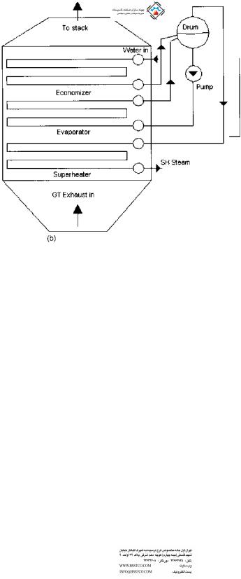
FIGURE 2.12 HRSGs with different type of circulation systems: (a) Natural circulation, (b) forced circulation. (c) Once-through.
Copyright © 2003 Marcel Dekker, Inc.
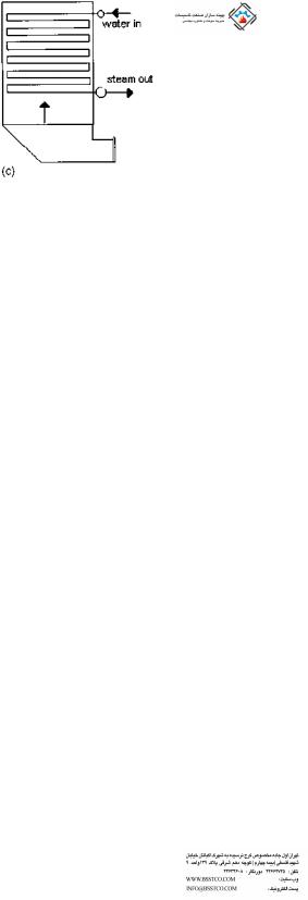
FIGURE 2.12 Continued.
the tubes, the water should have nearly zero solids. Otherwise deposition of solids can occur inside the tubes to the complete evaporation process. This in turn can lead to overheating of the tubes and consequent tube failure, particularly if the heat flux inside the tubes is high. Like natural or forced circulation units, these units generate singleor multiple-pressure saturated or superheated steam.
The concept of once-through steam generation is not new. Supercritical boilers in Europe have been using once-through designs for over half a century. A once-through unit does not have a defined economizer, evaporator, and superheater section. The location at which boiling starts keeps moving depending upon the gas flow, inlet gas temperature, and duty. The single-point control for the OTSG is the feedwater control valve; valve actuation depends on predefined operating conditions that are set through the distributed control system (DCS). The DCS is connected to a feedforward and feedback control loop, which monitors the transients in the gas turbine load and steam conditions. If a transient in the gas turbine load is monitored, the feedforward control sets the feedwater flow to a predicted value based on the turbine exhaust temperature, producing steady-state superheated steam conditions.
Because there is no steam drum, the water holdup is much less than in drum-type units. Often Alloy 800 or 825 tubes are used to ensure dry running and also to limit the sensitivity to oxygen in the water, avoiding the need for active chemical treatment. A gas bypass diverter system is not required, because of the dry operability. The use of high grade alloy tubes minimizes exfoliation concerns, which are likely with carbon steel or low grade alloy superheater tubes. When boiler tubes are heated, they form an oxide layer inside the tubes, and when cooler steam flows through them the oxide particles are dislodged and carried off to be deposited inside the steam turbine. This process, called exfoliation, occurs when the tubes are cycled frequently between hot and cold conditions.
Copyright © 2003 Marcel Dekker, Inc.
Once-through units can also be started up or shut down very fast compared to natural or forced circulation boilers, because the weight of steel and holdup of water are much smaller. On the flip side, the steam pressure decay when the gas turbine trips is likely to be faster than in designs that have much larger metal heat and a large water inventory. It must be kept in mind that a typical gas turbine HRSG can generally be started up in 80–100 min from cold, so the saving in start-up time may not be a significant issue unless the unit is designed for frequent cycling. There are also a few advantages of once-through units such as absence of downcomer and riser piping and drum and related material costs and fabrication concerns. From the heat transfer viewpoint there should not be much of a difference between once-through units and the natural or forced circulation units; hence the cross section and size of the HRSG or the areas of various heating surfaces should all be nearly the same. The flow configuration of the heating surfaces is generally counterflow except for the evaporator, which could be in parallel flow as in forced circulation units.
The two-phase steam-side pressure drop in the evaporator tubes is, however, quite large and could be in the range of a few hundred psi, which is an operating cost and must be considered in evaluating the design. In the natural and forced circulation unit, there is no additional pressure loss associated with the evaporator circuit, because the circulation system handles the losses and the static head available or the circulating pump balances this loss, considering other losses associated with the downcomer, evaporator tubes, and riser piping.
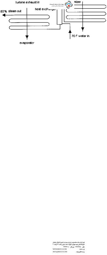
Another type of once-through unit is used in oil fields for secondary oil recovery operations (Fig. 2.13). These generate high pressure steam ranging from 1500 to 3000 psig at 80% quality for injection into used oil fields in order to recover additional oil. The steam pressure depends on the depth at which oil is available. The hot, wet steam dislodges the viscous layers of oil in the ground beneath, and thus more oil is recovered. This HRSG is also of once-through design, with water entering at one end of the coil and leaving as wet steam at the
FIGURE 2.13 HRSG used in oil field applications.
Copyright © 2003 Marcel Dekker, Inc.

other. Because of concerns with departure from nucleate boiling (DNB), the final portions of the coil are in parallel flow and not in counterflow and are located behind tubes having lower steam quality. This feature helps to lower the heat flux inside the tubes where the quality of steam is high. The allowable heat flux to avoid DNB decreases as the steam quality increases, hence this measure. The feedwater in these generators is generally of poor quality and has high solids content, exceeding thousands of ppm of salts, because the water is taken from the fields nearby and basic, inexpensive softening methods are used in its treatment. Because sodium salts are soluble in water, the 80% quality steam, which still has 20% water, is often adequate to ensure that the salts are disolved and are not deposited inside the tubes during the evaporation process. Single-stream designs, in which a single tube handles the entire steam flow, are used for up to 100,000 lb=h capacity, whereas with higher steam flows, multiple streams are employed. Due to instability problems associated with two-phase boiling of fluids with multiple streams, a flow resistance at the inlet to each stream in the form of orifices or control valves, as explained in Q7.36, is used. Because water at ambient temperature is often used as feedwater, a heat exchanger is used to preheat the incoming water, using the hotter water at the exit of the economizer portion to minimize acid dew point concerns.
Natural and Forced Circulation HRSGs
Figures 2.12b and 2.12c show the arrangement of natural and forced circulation HRSGs. In the natural circulation unit the differential head between the cold water in the downcomer circuit and the hotter, less dense mixture in the riser tubes drives the steam–water mixture through the evaporator tubes. The circulation ratio (CR), which is discussed in Q7.29, is typically on the order of 8–20 depending on the system, the layout, and the size of downcomers, evaporator tubes, and risers. The forced circulation units are sized for a particular CR, typically 3–6. The circulation pumps provide the additional differential head to ensure flow through the evaporator tubes. The following are some of the features of these types of HRSGs.
1.Natural circulation units do not require a pump for maintaining circulation through the evaporator tubes. The circulation is ensured through natural gravity principles. The use of circulating pumps in forced circulation units involves an operational and maintenance cost, and their failure for some reason such as power outage or pump failure could shut down the HRSG.
2.The water boils inside vertical tubes in natural circulation units, and the steam bubbles formed move upward, which is the natural path for them; hence the tube walls are completely wetted by water. As a result, tube failures are rare, whereas with horizontal tubes there is a
Copyright © 2003 Marcel Dekker, Inc.

difference in temperature between the top and bottom portions of the tubes, which could cause thermal fatigue. Also, if the steam–water mixture velocity is not high enough, the vapor can separate from the water inside the horizontal tubes, leading to steam blanketing and possibly overheating the tubes. This is a possibility when the heat flux inside the evaporator tubes is high, for example, in fired conditions, particularly when a high fin density is used for the evaporator tubes.
3.Natural circulation units can tolerate higher heat flux, generally 50– 80% more than horizontal tube designs due to the vertical configuration of the tubes. Also, in the event of nonuniform gas temperature or heat flux across the cross section (which is often likely due to maldistribution of gas flow), the tube receiving the higher heat flux in a natural circulation unit has a higher circulation ratio or higher steam–water mixture flow. This is due to the greater differential in fluid densities between the more dense fluid in the downcomer circuit and the less dense fluid inside the evaporator tubes, which is helpful and evens out flow imbalances. In a forced circulation unit, all the evaporator tubes receive the same steam–water flow, irrespective of their location, unless special efforts are taken to design the orifice in each tube as in controlled circulation utility boilers. Therefore severe gas-side flow and temperature maldistributions can lead to the possibility of tube failures or overheating in some tubes.
4.Natural circulation units require more real estate than forced circulation units, because heating surfaces are laid out one behind the other. The floor space occupied often runs into a few hundred square feet, particularly with multipressure units with catalysts for NOx and CO reduction. In forced circulation units the floor space may be small but the height of the HRSG will be large, requiring a large amount of supporting structural steel, ladders, and platforms.
5.During warm starts, the vertical, readily drainable superheater–reheater arrangement in natural circulation designs eliminates concerns over condensate carryover and impingement on hot headers and piping, which would result in thermal stresses at the headers.
6.The horizontal gas flow configuration of natural circulation HRSG provides an easy way to water wash the highly soluble ammonia compounds formed downstream of the SCR when operating with a sulfur-bearing fuel. A major deficiency of forced circulation or oncethrough units with their vertical gas path arrangement is the lack of a procedure to water wash deposits from heat transfer surfaces downstream of the SCR without damage to the SCR catalysts.
7.During start-up and low load periods, steam bubbles generated in the economizer section have to flow down in the counterflow direction in
Copyright © 2003 Marcel Dekker, Inc.

once-through and forced circulation units, which is not their natural path. To overcome steaming concerns, the feedwater control is sometimes located between the economizer and the evaporator. This increases the design pressure of the economizer. A safety valve is also required at the economizer.
8.The casing design for forced circulation units is typically ‘‘hot,’’ that is, it is insulated on the outside. Hence the designer is required to use alloy steel material for the casing, and one has to evaluate the impact of thermal expansion.
Despite their differences and the pros and cons, all three types of HRSGs are used throughout the world. Selection is generally based on the experience of the plant managers, their consultants, and the end users.
INCINERATION APPLICATIONS
In chemical and industrial plants, several by-products are generated in solid, liquid, and gaseous forms that have to be safely destroyed to prevent potential environmental damage. These by-products come from petroleum refining and petrochemical, pharmaceutical, paper and pulp, and plastics production. Small quantities of by-products are stored in drums and placed in landfills, but the most effective method of rapidly destroying a high percentage of hydrocarbon contaminants is to oxidize the organic materials at elevated temperatures (1500–1800 C). For some vapor streams, effective destruction of contaminants can be achieved at lower temperatures. The carbon and hydrogen in the waste are converted to CO2 and H2O. If the gas stream contains sulfur or chlorine or similar substances they must be recovered or removed before venting the flue gases to the atmosphere according to local air quality regulations. Particulates are also generated that have to be removed.
The process of thermal oxidation of fumes, liquids, and gaseous wastes is often carried out in thermal oxidizers or incinerators. If the waste stream has a low heating value or low concentration, often natural gas or liquid fuels are fired alongside to improve the combustion process. In order to destroy most of the pollutants, incineration is carried out at temperatures ranging from 1500 to 1800 F with proper residence times, typically 1–2 s. The exhaust gas stream contains a significant amount of energy and is recovered in the form of steam in waste heat boilers.
If the gas stream is greater than 100,000 lb=h and clean, then a water tube boiler with extended surfaces is the ideal choice. Fire tube boilers are also used in incineration plants if the gas is not likely to cause slagging. A superheater and economizer may also be used in fire tube boilers as shown in Fig. 2.2. Because of
Copyright © 2003 Marcel Dekker, Inc.

the high gas temperature at the inlet to the boiler, 1500–2000 F, the superheater is often located downstream of the boiler as shown. The superheater steam temperature cannot be very high, obviously, with such an arrangement; it is typically 500–550 F depending on the steam pressure. The disadvantage of the fire tube design is that it is difficult to have two fire tube boilers with a superheater in between such as can be done with water tube designs. Hence we have to live with a steam temperature that is slightly lower than those feasible with water tube designs. Locating the superheater at the gas inlet can lead to corrosion due to the presence of corrosive gases in the gas stream.
Bare and finned tubes are used in the design of water tube boilers, depending upon the cleanliness of the gas, its fouling tendencies, and the gas temperature. Simple two-drum designs, such as those shown in Chapter 8 in Fig. 8.3, in which the steam drum and mud drum are connected by plain or finned tubes rolled into the steam and mud drums, are common. This design can have either a refractory-lined casing or a water-cooled casing. With the refractory-lined design, casing corrosion is a possibility if the gas stream contains corrosive acid vapors that can seep through the refractory. Access doors or lanes can be easily incorporated into this design. The water-cooled casing operates at the saturation temperature of steam and ensures that corrosion concerns are minimal. The twodrum crossflow design is suitable for small capacities, generally about 50,000– 75,000 lb=h of steam. When the amount of steam generated is much greater say above 100,000 lb=h, an elevated steam drum with external downcomers and risers may be justified. The steam drum should have the volume or holdup to handle a few minutes of residence time from normal level to empty. Some plants require this residence time to be 3–4 min, and a few plants require 10–12 min. In large plants, multiple evaporators are connected to a common steam drum and circulation system.
Figure 2.3 shows a water tube boiler consisting of a screen section, followed by a two-stage superheater with interstage attemperation, an evaporator, and an economizer that is used in large incineration projects handling clean effluents. The screen section is similar to the shield section used in a fired heater and protects the superheater from the hot gases and from external radiation from the incinerator flame. A minimum of four rows are required to absorb the external radiation from the cavity or flame, as discussed in Q8.09. The evaporator and the screen sections are in parallel and are connected to the same steam drum by external downcomers and risers. If the gas enters at a temperature in excess of 1500 F, the screen section is often designed with bare tubes. The superheater may or may not have fins, depending on the steam and tube wall temperatures. The evaporator has finned surfaces, which can vary from a low fin density section at the inlet (two fins per inch) to a high fin density section (four to five fins per inch) as the gas is cooled. This is done to minimize the heat flux inside the tubes and also to minimize fin tip temperatures.
Copyright © 2003 Marcel Dekker, Inc.

The economizer uses a fin density of four to six fins per inch. The tubes of all the sections are generally vertical with horizontal gas flow, as in gas turbine HRSG plants. Superheaters are of T11, T22, or T91 material if the tube wall temperatures are close to 1000–1100 F.
In plants with large steam requirements, energy from the waste gas stream is augmented by firing natural gas or fuel oil. In these designs, a D-type boiler (Fig. 2.14) is an ideal choice. The burner is fitted at the front wall of the boiler and fires into a water-cooled furnace; the waste gas stream enters the convection bank, mixes with the furnace flue gases, then flows through the convection and economizer sections. A superheater can be located in the convection bank behind screen tubes. If the flue gases are clean, extended surfaces may be used in the cooler sections of the convection bank.
Various modes of operation have to be considered in these boilers, particularly if a superheater is used. If the waste gas stream supply is cut off, the steam generation is reduced. Hence the total steam flow is reduced which affects the steam temperature and the superheater tube wall temperatures. In some cases only the waste gas stream is used, and in some other modes only the burner is fired for generating steam. All these different cases generate different quantities of steam and flue gases at different temperatures that enter the convection section; hence the superheater performance has to be evaluated carefully in all these modes. The furnace pressure is maintained at nearly zero, and an induced draft fan handles the flow of the flue gases from the burner and the waste gas stream. The forced draft fan just handles the combustion air to the burner.
Figure 2.15 is the schematic of a waste heat boiler for a dirty gas from a carbon black incineration system. A D-type boiler was also used for this application. The hot gas coming in at about 2100 F is cooled in the furnace and then enters the convection bank. A screen section with widely spaced bare tubes helps to minimize slagging concerns with ash particulates that have low melting temperatures. A retractable blower also helps to clean the front end. As the gas cools, the tube spacing can be closer.
Slagging is a serious concern when flue gases containing ash particulates with low melting point salts are used in heat recovery applications. The slag is a rocklike deposit that forms on cool surfaces such as tubes and solidifies as soon as it is formed. Retractable blowers can help minimize this problem but cannot eliminate it completely. The wide tube spacing ensures that tubes are not bridged by the molten mass of deposits, thus preventing the flow of gases. Ash particles, if any, are collected in hoppers located beneath the convection bank.
FOULING IN WASTE HEAT BOILERS
Fouling is a serious concern in both fire tube and water tube boilers, particularly with dirty gas streams. It affects not only the waste heat boiler performance but
Copyright © 2003 Marcel Dekker, Inc.
FIGURE 2.14 D-type waste heat boiler for operation with burner and waste heat. (Courtesy of ABCO Industries, Abilene, TX.)
Copyright © 2003 Marcel Dekker, Inc.