

01 POWER ISLAND / 01 CCPP / V. Ganapathy-Industrial Boilers and HRSG-Design (2003)
.pdfgas contains less oxygen, on the order of 10–12% compared to 14–15% for turbine exhaust, making supplementary firing difficult, though not impossible.
There are two main sources of heat available in diesel engines. One is the engine cooling water, and the other is the exhaust gas (Fig. 1.21). The exhaust gas temperature is often below 750 F, hence only low pressure saturated or superheated steam is generated. Depending on the cleanliness of the gas stream, water tube boilers with extended surfaces could be used for heat recovery, though bare tube boilers with soot blower provisions are often used. Fire tube boilers are used if the gas flow is small, less than 50,000 lb=h. In many plants several diesel engines are used at the same time; hence by combining the exhaust gas flow into a single large duct, a single waste heat boiler could be built. The gas is often pulsating, so the boiler and casing design has to be rugged. Work is also being done to supplementary fire the diesel engine exhaust by using solid fuels to generate high pressure steam for combined cycle operation.
FIGURE 1.21 Diesel engine heat recovery system. Top: Combined cycle plant. Bottom: Diesel cogeneration.
Copyright © 2003 Marcel Dekker, Inc.

REFERENCES
1.JB Kitto. Developments in pulverized coal-fired boiler technology. Presented to Missouri Valley Electric Association Engineering Conference, Apr 10–12, 1996, Kansas City.
2.Supercritical Steam Power Cycles for Power Generation Applications. Report, Dept of Trade & Industry, London, UK, Jan 1999.
3.I Stambler. Kalina bottoming cycle 3.2 MW demo plant rated 26.9% efficiency. Gas Turbine World, March-April 1992.
4.J Corman. Kalina cycle looks good for combined cycle generation. Modern Power Systems Review, July 1995.
5.A Kalina. Kalina cycle promises improved efficiency. MPS Review, January 1987.
6.Editor. Enhancing gas turbine performance. Power, September 1995.
7.Boswell. Choose best options for enhancing combined cycle output. Power, September 1993.
8.GE Report. Advanced Technology Combined Cycles. General Electric Corp, October 2000.
9.Editor. Advanced gas turbines provide high efficiency and low emission. Power Engineering, March 1994.
10.US Dept of Energy. Clean Coal Technology Report—Wabash River Coal Gasification Repowering Project, November 1996.
11.V Ganapathy. Understand boiler performance characteristics. Hydrocarbon Processing, August 1994.
12.V Ganapathy. Heat-recovery steam generators: understand the basics. Chemical Engineering Progress, August 1996.
13.V Ganapathy. Efficiently generate steam from cogeneration plants. Chemical Engineering, May 1997.
14.D Franus. The gas turbine powered electrical power generation market 2001–2010. Cogeneration and On-Site Power Production, July–August 2001.
Copyright © 2003 Marcel Dekker, Inc.

2
Heat Recovery Boilers
INTRODUCTION
Heat recovery boilers, also known as waste heat recovery boilers or heat recovery steam generators (HRSGs), form an inevitable part of chemical plants, refineries, power plants, and process systems. They are classified in several ways, as can be seen in Fig. 2.1, according to the application, the type of boiler used, whether the flue gas is used for process or mainly for energy recovery, cleanliness of the gas, and boiler configuration, to mention a few. The main classification is based on whether the boiler is used for process purposes or for energy recovery. Process waste heat boilers are used to cool waste gas streams from a given inlet temperature to a desired exit temperature for further processing purposes. An example can be found in the chemical industry in a sulfuric acid or hydrogen plant where the gas stream is cooled to a particular gas temperature and then taken to a reactor for further processing. The exit gas temperature from the boiler is an important parameter affecting the downstream process reactions and hence is controlled by using a gas bypass system. Steam generation is of secondary importance in such plants. In energy recovery applications, on the other hand, the gas is cooled as much as possible while avoiding low temperature corrosion. Examples can be found in gas turbine exhaust heat recovery or flue gas heat
Copyright © 2003 Marcel Dekker, Inc.
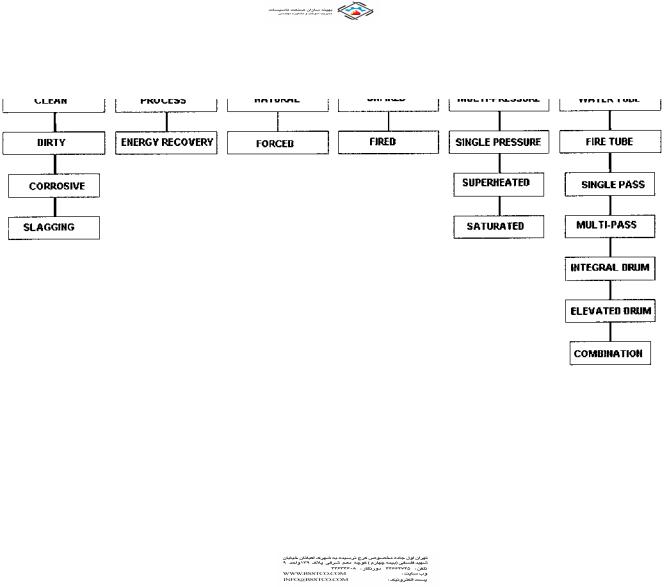
FIGURE 2.1 Classification of waste heat boilers.
Copyright © 2003 Marcel Dekker, Inc.

recovery from incinerators, furnaces, and kilns. The objective here is to maximize energy recovery.
If the gas stream is clean, water tube boilers with extended surfaces may be used. In solid or liquid waste incineration applications, the gas is generally dirty and may contain corrosive compounds, acid vapors, ash, and particulates. If the ash contains compounds of sodium, potassium, or nonferrous metals, slagging is likely on heat transfer surfaces if these compounds become molten. In these cases, bare tube boilers with provision for cleaning the tubes with soot blowers or a rapping mechanism are used. A water-cooled furnace, which cools the gas stream to a temperature below the ash melting temperature and hence minimizes slagging on the convective surfaces, may also be necessary.
Generally if the gas inlet temperature is high, say above 1400 F, a singlepressure heat recovery system is adequate to cool the gases to about 300–350 F. In gas turbine exhaust heat recovery applications with a low inlet gas temperature to the HRSG of 900–1000 F, a single-pressure heat recovery system cannot cool the gases adequately and a multipressure steam system is often required.
In the United States HRSGs are generally of natural circulation design, whereas in Europe it is very common to see once-through and forced circulation designs. The features of these boilers are discussed later.
Flue gas analysis is important to the design of the boiler. A large amount of water vapor or hydrogen increases the specific heat and thermal conductivity of the gas and hence the boiler duty and heat flux. For example, the reformed gas in hydrogen plants has a large volume of hydrogen and water vapor, which increases the heat transfer coefficient by 500–800% compared to typical flue gases. Hence heat flux is of concern in these types of boilers. Hydrogen chloride (HCl) vapor in the flue gases indicates corrosive potential, particularly if a superheater operating at high metal temperatures, say exceeding 900 F, is present. The presence of sulfur trioxide (SO3) vapor and HCl also suggests low temperature corrosion problems due to their low acid dew points. Flue gas pressure in waste heat boilers is typically atmospheric or a few inches of water column (in. WC) above or below atmospheric pressure; however, there are applications such as the use of a reformed gas boiler or synthesis gas boiler in hydrogen or ammonia plants where the gas pressure could be as high as 300–1500 psig (see Chap. 8, Table 8.46). Fire tube boilers are generally preferred for these applications, though special water tube boiler designed with heat transfer surfaces located inside pressure vessels have been built.
A common classification of boilers is based on whether the gas flows inside or outside the tubes. In fire tube boilers, the flue gases flow inside the tubes (Fig. 2.2), whereas in water tube boilers, the gas flows outside the tubes as shown in Fig. 2.3. The features of each type are discussed in the following section.
Copyright © 2003 Marcel Dekker, Inc.

FIGURE 2.2 Fire tube waste heat boiler with superheater and economizer. (Courtesy of ABCO Industries, Abilene, TX.)
Copyright © 2003 Marcel Dekker, Inc.
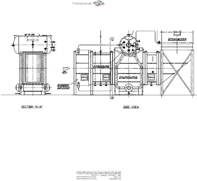
FIGURE 2.3 Water tube waste heat boiler with superheater and economizer. (Courtesy of ABCO Industries, Abilene, TX.)
Copyright © 2003 Marcel Dekker, Inc.

WATER TUBE VERSUS FIRE TUBE BOILERS
Table 2.1 shows a few aspects of fire tube and water tube waste heat boilers. Generally water tube boilers are suitable for large gas flows exceeding millions of pounds per hour and can handle high steam pressures and temperatures. Fire tube boilers are suitable for low steam pressures, generally below 500 psig. Table 2.2 shows the effect of pressure on tube thickness in both types of boilers, and one can see why fire tube boilers are not suggested for high steam pressure applications.
In water tube boilers, extended surfaces can be used to make them compact if the gas stream is clean, as discussed in Q8.21. Flue gas pressure drop will also be lower than for an equivalent fire tube boiler owing to the compactness of the design. Water tube boilers can be smaller and weigh less, particularly if the gas flow is large, exceeding 100,000 lb=h. Superheaters can be used in both types. In a water tube boiler they can be located in an optimum gas temperature zone. A shield screen section or a large convection section precedes the superheater. In a fire tube boiler, the superheater has to be located at either the gas inlet or exit, making the design less flexible and vulnerable to slagging or corrosion. If the waste gas is slagging in nature, a water tube boiler is desired because the surfaces can be cleaned by using retractable soot blowers. In general, the type of boiler to
TABLE 2.1 A Comparison of Fire Tube and Water Tube Boilers
Variable |
Fire tube boiler |
Water tube boiler |
|
|
|
Gas flow |
Small—less than |
50,000 to millions of |
|
50,000 lb=h |
lb=h |
Gas inlet temperature |
Low to adiabatic |
Low to adiabatic |
|
combustion |
combustion |
Gas pressure |
High—even as high |
Generally less than |
|
as 2000 psig |
2 psig |
Firing |
Possible |
Possible |
Type of heating surface |
Bare tube |
Bare and finned tubes |
Superheater location |
At inlet or exit of boiler |
Anywhere in the gas |
|
|
path using screen |
|
|
section |
Water inventory |
High |
Low |
Heat flux-steam side |
Generally low |
Can be high with finned |
|
|
tubes |
Multiple steam pressure |
No |
Yes |
Soot blower location |
Inlet or exit of boiler |
Anywhere inside boiler |
|
|
surfaces |
Multiple modules |
No |
Yes |
|
|
|
Copyright © 2003 Marcel Dekker, Inc.

TABLE 2.2 Tube Thickness vs. Steam Pressure—ASME Sec 1
Tube thicknessa |
External pressure |
Internal pressure |
(in.) |
(psig) |
(psig) |
|
|
|
0.105 |
575 |
1147 |
0.120 |
686 |
1339 |
0.135 |
800 |
1533 |
0.150 |
921 |
1730 |
0.180 |
1172 |
2137 |
a2 in. OD, SA 178a and SA 192 carbon steel tubes at 700 F.
be used for a particular case is determined by the experience of the manufacturer. Sometimes a combination of fire and water tube boilers is used to suit special needs.
HEAT RECOVERY IN SULFUR PLANTS
A sulfur plant forms an important part of a gas processing system in a refinery. Sulfur is present in natural gas as hydrogen sulfide (H2S); it is the by-product of processing natural gas and refining high sulfur crude oils. For process and combustion applications, the sulfur in the natural gas has to be removed. Sulfur recovery refers to the conversion of hydrogen sulfide to elemental sulfur. The most common process for sulfur removal is the Claus process, which recovers about 95–97% of the hydrogen sulfide in the feedstream. Waste heat boilers are an important part of this process (Fig. 2.4).
The Claus process used today is a modification of a process first used in 1883, in which H2S was reacted over a catalyst with air to form elemental sulfur and water. The reaction is expressed as
H2S þ 1=2O2 ! S þ H2O
Control of this exothermic reaction was difficult, and sulfur recovery efficiency was low. Modifications later included burning one third of the H2S to produce sulfur dioxide, SO2, which is reacted with the remaining H2S to produce elemental sulfur. This process consists of multistage catalytic oxidation of hydrogen sulfide according to the reactions
2H2S þ 3O2 ! 2SO2 þ 2H2O þ heat 2H2S þ O2 ! 2S þ 2H2O
Each catalytic stage consists of a gas reheater, a catalyst chamber, and a condenser as shown in Fig. 2.4.
Copyright © 2003 Marcel Dekker, Inc.
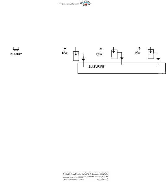
FIGURE 2.4 Claus process for sulfur recovery.
Copyright © 2003 Marcel Dekker, Inc.