

01 POWER ISLAND / 01 CCPP / V. Ganapathy-Industrial Boilers and HRSG-Design (2003)
.pdfFIGURE 8.25a Strouhal number for in-line bank of tubes.
Copyright © 2003 Marcel Dekker, Inc.
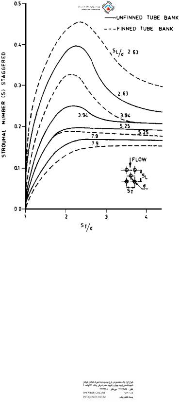
FIGURE 8.25b Strouhal number for staggered bank of tubes.
8.59e
Q:
A tubular air heater 11.7 ft wide, 12.5 ft deep, and 13.5 ft high is used in a boiler. Carbon steel tubes of 2 in. OD and 0.08 in. thickness are used in in-line fashion with a transverse pitch of 3.5 in. and longitudinal pitch of 3.0 in. The heater is 40 tubes wide (3.5 in. pitch) and 60 tubes deep (2.5 in. pitch). Air flow across the
Copyright © 2003 Marcel Dekker, Inc.

FIGURE 8.25c,d Strouhal number (c) for staggered bank of tubes (top), (d) for inline bank of tubes (bottom).
Copyright © 2003 Marcel Dekker, Inc.
tubes is 300,000 lb=h at an average temperature of 219 F. The tubes are fixed at both ends in tube sheets. Check whether bundle vibrations are likely. Tube mass per unit length ¼ 1.67 lb=ft.
A:
First compute fa; fe, and fn. L ¼ 13.5 ft, do ¼ 2 in., di ¼ 1.84 in., Me ¼ 1.67 lb=ft, and, from Table 8.41, C ¼ 22.37.
Using Eq. (114b), we have
f |
90 22:37 |
ð24 1:844Þ0:5 |
|
18:2 Hz |
|
ð13:5Þ2 |
ð1:67Þ0:5 |
¼ |
|||
n ¼ |
|
This is in mode 1. In mode 2, C ¼ 61.67; hence fn2 is 50.2 Hz. (The first two modes are important.)
Let us compute fe. S from Fig. 8.25 for ST =do ¼ 3.5=2 ¼ 1.75 and a longitudinal pitch of 3.0=2 ¼ 1.5 is 0.33.
From Eq. (1) of Chapter 5, r ¼ 40=(219 þ 460) ¼ 0.059 lb=cu ft. Free gas area ¼ 40 ð3:5 2Þ 13:5=12 ¼ 67:5 lb=ft2 h
(13.5 is the tube length, and 40 tubes wide is used with a pitch of 3.5 in.) Hence air velocity across tubes is
300;000
V ¼ 67:5 3600 0:059 ¼ 21 ft=s
Hence |
|
|
|
|
|
|
|
|
f |
12SV |
¼ |
12 |
|
|
0:33 21 |
¼ |
41:6 Hz |
|
|
|||||||
e ¼ |
do |
|
2 |
|
||||
Let us compute fa. T ¼ (219 þ 460) ¼ 679 R. Hence Vs ¼ 49 6790:5 ¼ 1277 ft=s. Width W ¼ 11.7 ft, and l ¼ 2 11.7 ¼ 23.4 ft. For mode 1 or n ¼ 1,
fa1 ¼ 1277=23:4 ¼ 54:5 Hz
For n ¼ 2,
fa2 ¼ 54:5 2 ¼ 109 Hz
The results for modes 1 and 2 are summarized in Table 8.42. It can be seen that without baffles the frequencies fa and fe are within 20% of each other. Hence noise problems are likely to arise. If a baffle or plate is used to divide the duct width into two regions, the acoustic frequency is doubled as the wavelength or width is halved. This is a practical solution to acoustic vibration problems.
Copyright © 2003 Marcel Dekker, Inc.

TABLE 8.42 Summary of Frequencies for Modes 1 and 2
Mode of vibration n |
1 |
2 |
|
|
|
fn (cps or Hz) |
18.2 |
50.2 |
fe (cps or Hz) |
41.6 |
41.6 |
fa (without baffles) |
54.5 |
109 |
fa (with one baffle) |
109 |
218 |
8.59f
Q:
What are the other checks for ensuring that tube bundle vibrations are minimized? The vortex shedding frequencies often coincide with acoustic frequency, and often no standing waves develop and the transverse gas column does not vibrate. Resonance is more the exception than the rule. Chen proposed a damping criterion C based on tube geometry as follows [1]:
C |
¼ |
Re |
|
Sl=d 1 |
|
2 |
d |
ð |
117 |
Þ |
|
|
S |
Sl=d |
|
St |
|||||||
|
|
|
|
||||||||
where St and Sl are the transverse and longitudinal spacing and d is the tube diameter. The method of calculating the Strouhal number S is given in Q8.59d. For an in-line bank of tubes without fins, Chen stated that C must exceed 600 before a standing wave develops. A large variation in C exists in practice. According to one study, in spiral finned economizers C reached 15,000 before a sonic vibration developed. If C is less than 2000, then vibrations due to vortex shedding may not occur. Vibration analysis is not an exact science, and a lot of it is based on experience operating units of similar design. In some cases the calculations showed that the vortex shedding and acoustic frequencies were matching but no damaging vibrations occurred.
ASME Sec. 3 Appendix N 1330, 1995 on flow-induced vibration suggests that if the reduced damping factor C exceeds 64 where
C ¼ 4pmx=rd2 |
ð118Þ |
then vortex shedding is unlikely to cause damage. This is due to the large mass of the system compared to the low energy in the gas stream. In Eq. (118),
m ¼ mass per unit length of tube, lb=ft
x ¼ damping factor (typically 0.001 for systems with no intermediate support and 0.01 for systems with intermediate supports)
r ¼ gas density, lb=ft3 d ¼ tube OD, in.
Copyright © 2003 Marcel Dekker, Inc.
Table 8.43 shows the results of calculations for a waste heat boiler that has both bare and finned tubes. The high gas temperature region at the entrance section has bare tubes, and the cooler section has finned tubes.
Coincidence of vortex shedding frequency with the natural frequency in the fourth mode is not a concern. Due to the low amplitudes at lower modes, tube damage is unlikely. Also, owing to the high value of C, which exceeds 64, vortex shedding is unlikely to cause tube damage.
Fluid Elastic Instability
The need for intermediate tube supports is governed by fluid elastic instability considerations. ASME Sec. 3 gives an idea of the stability of tube bundles. If the nondimensional flow velocity as a function of mass damping factor is above the curve shown in Fig. 8.26, then intermediate supports are required; without them fretting and wear of tubes due to vibration is possible. Basically this criterion tells us that if we have a tall tube bundle without intermediate supports, it can oscillate due to the gas flow; intermediate supports help to increase the natural frequency of the tubes and thus reduce the nondimensional flow velocity, making the bundle design more stable. Using the criterion showed that intermediate supports are required even for short boilers (under 12 ft high). However, based on my experience designing several hundred water tube waste heat boilers that are now in operation, the boilers operated well without intermediate supports, indicating once again the generality of these types of analysis. One has to consider operational experience of a similar unit along with these calculation procedures before modifying any boiler design.
TABLE 8.43 Damping Factors for Evaporator Tubes
Item |
Bare tube section |
Finned section |
|
|
|
Gas temperature, F |
1600 |
510 |
Gas density, lb=ft3 |
0.0188 |
0.0394 |
Gas velocity, ft=s |
53.9 |
25.8 |
Fins |
No |
2 0.75 0.075 in. |
Tube mass, lb=ft |
3.132 |
7.33 |
Tube span, ft |
17.33 |
17.33 |
Strouhal number S |
0.25 |
0.25 |
Vortex shedding frequency, Hz |
80.85 |
38.66 |
Damping factor |
0.01 |
0.01 |
Factor C |
753 |
845 |
Tube natural freq, Hz |
8.8, 24, 48, 79 |
5.7, 16, 31, 51.6 |
Amplitude, in. |
0.0018 |
0.00167 |
|
|
|
Copyright © 2003 Marcel Dekker, Inc.

FIGURE 8.26 Damping factor versus nondimensional flow velocity.
Example
In a boiler with mass per unit length m ¼ 3.132 lb=ft, damping factor x ¼ 0.001, gas velocity ¼ 87 ft=s, and gas density r ¼ 0.0188 lb=ft3, d ¼ 2 in.
Mass damping factor ¼ 2pmx ¼ 2p 3:132 0:001 144=ð0:0188 22Þ d2r
¼ 37:7
Nondimensional velocity ¼ 12U=fd, where f ¼ natural frequency of vibration, Hz; U ¼ gas velocity, ft=s; and d ¼ tube outer diameter, in.
Based on previous calculations, f ¼ 20.6 Hz. Hence
Flow velocity ¼ 87 12=ð20:6 2Þ ¼ 25:5
It can be seen from Fig. 8.26 that this is a borderline case and that an intermediate support would have further increased the natural frequency and made the flow velocity fall within the stable region. In practice, for tall tube bundles, intermediate supports at 11–15 ft intervals are used.
8.60
Q:
How are the gas properties Cp; m, and k estimated for a gaseous mixture? Determine Cp; m, and k for a gas mixture having the following analysis at 1650 F and 14.7 psia.
Copyright © 2003 Marcel Dekker, Inc.

Gas |
Vol% |
Cp |
m |
k |
MW |
N2 |
80 |
0.286 |
0.108 |
0.030 |
28 |
O2 |
12 |
0.270 |
0.125 |
0.043 |
32 |
SO2 |
8 |
0.210 |
0.105 |
0.040 |
64 |
Mixture properties are needed to evaluate heat transfer coefficients. For flue gas obtained from the combustion of fossil fuels, in the absence of flue gas analysis, one can use the data on air.
A:
For a gaseous mixture at atmospheric pressure, the following relations apply. For high gas pressures, readers are referred to Ref. 1.
mm ¼ |
|
|
yimi MWi |
|
|
|
|
|
|
|
|
|
|
|
|
|
|
|
|
|
|
|
|
ð119aÞ |
|||||||||
|
|
|
|
|
y |
|
|
|
MW |
|
|
|
|
|
|
|
|
|
|
|
|
|
|
|
|
|
|
|
|
|
|
|
|
|
|
|
|
P |
i |
pi |
|
|
|
|
|
|
|
|
|
|
|
|
|
|
|
|
|
|
|
|
|
|
|||||
|
|
|
|
|
|
|
p3 |
|
|
|
|
|
|
|
|
|
|
|
|
|
|
|
|
|
|
|
|
|
|
|
|
||
|
|
|
|
|
P |
p |
|
|
|
|
|
|
|
|
|
|
|
|
|
|
|
|
|
|
|
|
|
|
|
||||
km ¼ |
|
|
|
|
|
MWi |
|
|
|
|
|
|
|
|
|
|
|
|
|
|
|
|
|
|
|
|
ð119bÞ |
||||||
|
|
yiki y |
|
3 MW |
|
|
|
|
|
|
|
|
|
|
|
|
|
|
|
|
|
|
|
|
|||||||||
|
|
|
P |
|
|
i |
|
i |
|
|
|
|
|
|
|
|
|
|
|
|
|
|
|
|
|
|
|
|
|
||||
|
|
|
|
|
|
|
|
|
q |
|
|
|
|
|
|
|
|
|
|
|
|
|
|
|
|
|
|
|
|
|
|||
|
|
|
|
|
Cpi MW yi |
|
|
|
|
|
|
|
|
|
|
|
|
|
|
|
|
|
|
|
|
||||||||
Cpm ¼ |
P |
|
MW |
|
yi |
|
|
|
|
|
|
|
|
|
|
|
|
|
|
|
|
|
|
|
ð119cÞ |
||||||||
where |
|
|
|
|
P |
|
|
|
|
|
|
|
|
|
|
|
|
|
|
|
|
|
|
|
|
|
|
|
|
|
|
|
|
MW ¼ molecular weight |
|
|
|
|
|
|
|
|
|
|
|
|
|
|
|
|
|
|
|
||||||||||||||
|
|
y ¼ volume fraction of any constituent |
|
|
|
|
|
|
|
|
|||||||||||||||||||||||
Subscript m stands for mixture. |
|
|
|
|
|
|
|
|
|
|
|
|
|
|
|
|
|
|
|||||||||||||||
Substituting into Eqs. (119), we have |
|
|
|
|
|
|
|
|
|
|
|
||||||||||||||||||||||
C |
pm ¼ |
0:286 0:8 28 þ 0:27 0:12 32 þ 0:21 0:08 64 |
|
|
|||||||||||||||||||||||||||||
|
|
|
|
|
|
|
0:8 |
|
28 |
þ |
0:12 |
|
32 |
þ |
0:08 |
|
64 |
|
|
|
|||||||||||||
|
|
|
|
|
|
|
|
|
|
|
|
|
|
|
|
|
|
|
|
|
|
|
|
|
|
||||||||
|
|
¼ |
0:272 Btu=lb F |
|
|
|
|
|
|
|
|
|
|
|
|
|
|
|
|
|
|
|
|
||||||||||
|
|
|
|
|
|
|
|
|
|
|
|
|
|
|
|
|
|
|
|
|
|
|
|
|
|
|
|
|
|
|
|||
k |
m ¼ |
0:03 281=3 0:80 þ 0:043 321=3 0:12 þ 0:04 641=3 0:08 |
|
||||||||||||||||||||||||||||||
|
|
|
|
|
|
|
|
281=3 0:80 þ 321=3 0:12 þ 641=3 0:08 |
|||||||||||||||||||||||||
|
|
¼ |
0:032 Btu=ft F |
|
|
|
|
|
|
|
|
|
|
|
|
|
|
|
|
|
|
|
|
|
|||||||||
|
|
|
|
|
|
|
|
p |
|
|
|
|
|
|
|
|
|
|
|
|
p |
|
|
|
|
|
|
|
p |
||||
mm ¼ |
|
0:108 28 0:8 þ 0:125 |
|
|
32 0:12 þ 0:105 64 0:08 |
||||||||||||||||||||||||||||
|
|
|
|
|
|
|
p |
|
|
|
|
|
|
|
p |
|
|
|
0:12 |
p64 |
|
0:105 |
|
|
|||||||||
|
|
|
|
|
|
|
|
|
|
|
|
28 |
|
|
0:8 |
|
|
32 |
|
|
|
|
|
|
|
|
|
||||||
|
|
¼ 0:109 lb=ft h |
|
|
|
|
|
þ |
|
|
|
|
|
þ |
|
|
|
|
|||||||||||||||
Copyright © 2003 Marcel Dekker, Inc.
8.61
Q:
How do gas analysis and pressure affect heat transfer performance?
A:
The presence of gases such as hydrogen and water vapor increases the heat transfer coefficient significantly, which can affect the heat flux and the boiler size. Also, if the gas is at high pressure, say 100 psi or more, the mass velocity inside the tubes (fire tube boilers) or outside the boiler tubes (water tube boilers) can be much higher because of the higher density, which also contributes to the higher heat transfer coefficients. Table 8.44 compares two gas streams, reformed gases from a hydrogen plant and flue gases from combustion of natural gas.
Factors C and F used in the estimation of heat transfer coefficients inside and outside the tubes are also given in Table 8.44. It can be seen that the effect of gas analysis is very significant. Even at low gas pressures of reformed gases (50– 100 psig), the factors C and F would be very close to the values shown, within 2– 5%.
8.62
Q:
How does gas pressure affect the heat transfer coefficient?
TABLE 8.44 Effect of Gas Analysis on Heat Transfer
|
Reformed gas |
Flue gas |
||
|
|
|
|
|
CO2, vol% |
|
5.0 |
|
17.45 |
H2O, vol% |
|
38.0 |
|
18.76 |
N2, vol% |
|
— |
|
62.27 |
O2, vol% |
|
— |
|
1.52 |
CO, vol% |
|
9.0 |
|
— |
H2, vol% |
|
45.0 |
|
— |
CH4, vol% |
|
3.0 |
|
— |
Gas pressure, psia |
400 |
|
15 |
|
Temp, F |
1550 |
675 |
1540 |
700 |
Cp, Btu=lb F |
0.686 |
0.615 |
0.320 |
0.286 |
m, lb=ft h |
0.087 |
0.056 |
0.109 |
0.070 |
k, Btu=ft h F |
0.109 |
0.069 |
0.046 |
0.028 |
Factor Ca |
|
0.571 |
|
0.225 |
Factor Fa |
|
0.352 |
|
0.142 |
|
|
|
|
|
aC ¼ ðCp =mÞ0:4k0:6; |
F ¼ Cp0:33k0:67=m0:27. |
|
|
|
Copyright © 2003 Marcel Dekker, Inc.

A:
The effect of gas pressure on factors C and F for some common gases is shown in Figs. 8.27 and 8.28. It can be seen that the pressure effect becomes smaller at high gas temperatures, while at low temperatures there is a significant difference. Also, the pressure effect is small and can be ignored up to a gas pressure of 200 psia.
8.63
Q:
How do we convert gas analysis in percent by weight to percent by volume?
A:
One of the frequent calculations performed by heat transfer engineers is the conversion from weight to volume basis and vice versa. The following example shows how this is done.
Example
A gas contains 3% CO2, 6% H2O, 74% N2, and 17% O2 by weight. Determine the gas analysis in volume percent.
Solution. Moles of a gas are obtained by dividing the weight by the molecular weight; moles of CO2 ¼ 3=44 ¼ 0.06818.
The volume of each gas, then, is the mole fraction 100. Percent volume of O2 ¼ (0.5312=3.57563) 100 ¼ 14.86, and so on. One can work in reverse and convert from volume (or mole) basis to weight basis.
Gas |
W% |
MW |
Moles |
Vol% |
|
|
|
|
|
CO2 |
3 |
44 |
0.06818 |
1.91 |
H2O |
6 |
18 |
0.3333 |
9.32 |
N2 |
74 |
28 |
2.6429 |
73.91 |
O2 |
17 |
32 |
0.5312 |
14.86 |
Total |
|
|
3.57563 |
100 |
|
|
|
|
|
8.64
Q:
What is the effect of gas pressure and gas analysis on design of a fire tube waste heat boiler? Compare the following two cases. In case 1, reformed gas in a
Copyright © 2003 Marcel Dekker, Inc.