

01 POWER ISLAND / 01 CCPP / V. Ganapathy-Industrial Boilers and HRSG-Design (2003)
.pdfSubstituting the various quantities into Eq. (42b),
r
2 9:8
m ¼ |
|
|
|
|
184 106 |
80 |
þ |
4:6 |
|||
|
|
|
|
|
|
¼ |
6530 kg=m2 s |
||||
The two values m and mc do not agree. Hence we have to repeat the calculations for another Pc.
This has been done for Pc ¼ 30 and 15, and the results are presented in Fig. 7.15. At about 19 atm, the two curves intersect, and the mass flow rate is about 7000 kg=m2 s. However, one may do the calculations at this pressure and check.
Use of Charts
As seen above, the procedure is lengthy and tedious, and trial and error is involved. Also, reference to steam tables makes it cumbersome. Hence with various K values and initial pressure Ps, a calculator was used to solve for Pc and m, and the results are presented in Figs. 7.16 and 7.17.
FIGURE 7.15 Calculation results.
Copyright © 2003 Marcel Dekker, Inc.
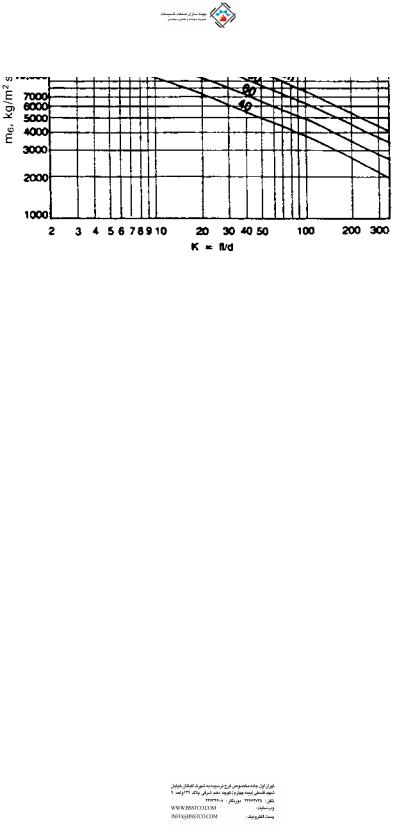
FIGURE 7.16 Solving for m.
FIGURE 7.17 Solving for P.
Copyright © 2003 Marcel Dekker, Inc.

7.35
Q:
What is the effect of stack height on friction loss and draft?
A:
Whenever hot flue gases flow in a vertical stack, a natural draft is created owing to the difference in density between the low density flue gases and ambient air, which has a higher density. However, due to the friction losses in the stack, this available draft is reduced.
Example
If 100,000 lb=h of flue gases at 400 F flow in a 48 in. ID stack of 50 ft height, determine the net stack effect. Ambient air temperature is 70 F.
Solution. Density of flue gases |
(see Q5.02) at 400 F ¼ 39.5=860 ¼ |
|||
0.0459 lb=cu ft. Density of air at 70 F ¼ 40=530 ¼ 0.0755 lb=cu ft. Hence |
||||
Total draft available ¼ ð0:0755 |
0:0459Þ 50 |
|
|
|
¼ 1:48 lb=ft2 |
|
12 |
|
|
¼ ð0:0755 |
0:0459Þ 50 |
|
||
|
|
|
||
62:4 |
|
|||
¼ 0:285 in: WC |
|
|
|
|
(The factor 62.4 is density of water, and 12 converts ft to in.)
Let us see how much the friction loss per unit length is. From Eq. (26),
DP ¼ 93 10 6 f W 2 dv5
v ¼ 1=0.0459 ¼ 21.79 cu ft=lb. To estimate the friction factor f , we need the Reynolds number. From the Appendix, m ¼ 0.058 lb=ft h. Hence
100,000
Re ¼ 15:2 48 0:058 ¼ 546,000
0:316
f ¼ ð546;000Þ0:25 ¼ 0:012
D P ¼ 93 10 6 0:012 ð100;000Þ2 50 21:79 485
¼ 0:048 in: WC
Hence
Net draft available ¼ 0:285 0:048 ¼ 0:237 in: WC
Copyright © 2003 Marcel Dekker, Inc.

7.36
Q:
Discuss the flow instability problem in boiler evaporators.
A:
In once-through boilers or evaporators generating steam at high quality, the problem of flow instability is often a concern. This is due to the nature of the twophase pressure drop characteristics inside tubes, which can have a negative slope with respect to flow under certain conditions. The problem is felt when multiple streams are connected to common header systems as in once-through or forced circulation systems. Small perturbations can cause large changes in flow through a few tubes, resulting in possible dryout or overheating conditions. Vibration can also occur. The problem has been observed in a few low pressure systems generating steam at high quality.
To illustrate the problem, let us take up the example of steam generation inside a tube. For the sake of analysis, a few assumptions will be made:
Heat flux is uniform along the length of the tube, Steam at the exit of the tube has a quality x,
Some subcooling of feedwater is present. That is, the feedwater enters the boiler at less than the saturation temperature.
We are considering a long straight tube without bends to describe the nature of the problem.
If a tube is supplied with subcooled water, the boiling starts after the enthalpy of the water has risen to the saturated liquid level. Thus the length of the boiler can be divided into two portions, the economizer portion and the evaporator, their lengths being determined by the heat input to their respective sections.
Let W be the flow of water entering in lb=h. Let Q ¼ total heat input to the evaporator and Ql the heat input per unit length, Btu=ft h. The steam quality at the exit of the evaporator is x, fraction. Let the economizer length be L1 ft. The pressure drop DP1 in the economizer section is
D P1 ¼ 3:36f L1W 2vf =di5 |
ð45Þ |
where |
|
L1 ¼ W Dh=Ql |
ð46Þ |
Dh ¼ enthalpy absorbed by water in the economizer portion,3 Btu=lb |
|
vf ¼ average specific volume of water in the economizer, ft |
=lb |
In Eq. (46) we are simply using the fact that heat addition is uniform along the tube length.
di ¼ tube inner diameter, in.
Copyright © 2003 Marcel Dekker, Inc.

The pressure drop in the evaporator region of length L L1 |
is given by |
|
|
||||||
DP2 ¼ 3:36f ðL L1ÞW |
2 vf þ xðvg vf Þ=2 |
ð47Þ |
|||||||
|
di5 |
|
|||||||
Now |
|
|
|
|
|
|
|
||
xhfg |
L L1 |
|
|
|
|
48 |
|
||
|
|
|
|
|
|
|
|
||
|
Dh ¼ |
L1 |
|
|
|
ð |
Þ |
||
|
|
|
|
|
|||||
because the heat applied is uniform along the evaporator length, and we are simply taking the ratio of energy absorbed in the evaporator and economizer, which is proportional to their lengths.
hfg ¼ latent heat of vaporization, Btu=lb
vg; vf ¼ specific volume of saturated liquid and vapor, ft3=lb
Now substituting for x from Eq. (48) in. to Eq. (47) and for L1 from Eq. (46) and simplifying the above equations, we can obtain the total pressure drop as
follows. |
|
|
|
|
|
|
|
|
|
|
|
DP ¼ DP1 þ DP2 |
|
kW |
|
Dh hfg |
vf |
! þ kWL |
Ql |
2hfg |
|||
¼ kW |
Dh |
2Qlhfg |
|
||||||||
3 |
|
2 vg |
vf |
|
2 |
|
vg vf |
|
2 |
|
vg vf |
or |
|
|
|
|
|
|
|
|
|
|
ð49Þ |
|
|
|
|
|
|
|
|
|
|
|
|
DP ¼ AW 3 BW 2 þ CW |
|
|
|
|
|
|
ð50Þ |
||||
Though this is a simplistic analysis for two-phase flow pressure drop, it may be used to show the effect of the variables on the process.
Equation (50) is shown in Fig. 7.18. It is seen that the curve of pressure drop versus flow is not monotonic but has a negative slope. This is more so if the steam pressure is low. Hence it may lead to unstable conditions. For example, at the pressure drop condition shown by the horizontal line, there could be three possible operating points, which may cause oscillations and large variations in flow through the circuit. This is likely if multiple streams are connected between headers, where a few tubes can receive very small flows, causing tube overheating concerns and possible DNB conditions.
To improve the situation, one may add a restriction such as a control valve or orifice at the inlet to the economizer section. The orifice increases the resistance in proportion to the square of the flow as shown by the term R in Eq. (51). Figure 7.18a also shows the effect of the orifice, which makes the
pressure drop curve monotonic. |
|
DP ¼ AW 3 þ ðR BÞW 2 þ CW |
ð51Þ |
Copyright © 2003 Marcel Dekker, Inc.
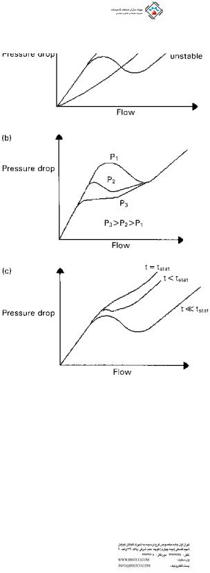
FIGURE 7.18 Effect of (a) orifice size, (b) pressure, and (c) inlet subcooling on the stability of two-phase boiling circuits.
Because the ratio of specific volumes of steam and water is much larger at low steam pressures and the latent heat is also large, the problem is more likely at low pressures than at high pressures, as indicated in Fig 7.18b. Decreasing the inlet subcooling by using a higher feedwater temperature also helps as shown in
Copyright © 2003 Marcel Dekker, Inc.

Fig. 7.18c. If inlet subcooling is eliminated, Dh ¼ 0 and then Eq. (50) becomes more stable as shown by the equation
DP ¼ BW 2 þ CW |
ð52Þ |
NOMENCLATURE
AArea of orifice, in.2
CA constant depending on ratio of gas specific heats
CR |
Circulation ratio |
Cd |
Discharge coefficient |
Cv |
Control valve coefficient |
dTube or pipe outer diameter, in.
do; di |
Orifice diameter and pipe or duct inner diameter, in. |
EExpansion factor for fuel oils
f |
Friction factor |
GGas mass velocity, lb=ft2 h
hDifferential pressure across flow meter, in. WC
he |
Enthalpy |
of mixture at exit, Btu=lb |
hf ; hg; hm; hfw |
Enthalpy |
of saturated liquid, saturated steam, mixture, and |
|
feedwater, Btu=lb |
|
KSystem resistance
Km |
Valve recovery coefficient |
Ksh |
Superheat correction factor |
LLength of pipe, ft
Le |
Equivalent length, ft |
MConstant used in Q7.25
m |
mass flow at critical condition, kg=m2 s |
c |
|
MW |
Molecular weight of gas or vapor |
NH |
Number of rows deep in a tube bundle |
Pa |
Accumulated inlet pressure, psia |
Pb |
Backpressure, psig |
Ps |
Set pressure, psig |
Pv |
Vapor pressure, psia |
P1; P2 |
Inlet and exit pressures, psia |
DP |
Pressure drop, psi |
DPg |
Gas pressure drop, in. WC |
DPa; DPf ; DPg |
Acceleration loss, friction loss, and loss due to gravity, psi |
qFluid flow, gpm
Re |
Reynolds number |
r2; r3; r4; rf |
Factors used in two-phase pressure drop calculation |
SEntropy
s |
Specific gravity of fluid |
Copyright © 2003 Marcel Dekker, Inc.

ST ; SL |
Transverse and longitudinal pitch, in. |
t; T |
Fluid temperature, F or R |
ts |
Saturation temperature, F |
v |
Specific volume of fluid, cu ft=lb |
Vc |
Critical velocity, m=s |
VFluid velocity, ft=s
vf ; vg; vm |
Specific volume of saturated liquid, steam, and mixture, cu ft=lb |
WFlow, lb=h
x |
Steam quality, fraction |
y |
Volume fraction of gas |
YExpansion factor
bdo=di ratio
m |
Fluid viscosity, lb=ft h |
r |
Density of fluid, lb=cu ft; subscript g stands for gas |
m |
Specific volume of fluid, m3=kg |
REFERENCES
1.V Ganapathy. Determining flowmeter sizes. Plant Engineering, Sept 18, 1980, p 127.
2.Chemical Engineers’ Handbook. 5th ed. New York: McGraw-Hill, 1974, pp 5–7.
3.V Ganapathy. Converting pitot tube readings. Plant Engineering, June 24, 1982, p 61.
4.ASME. Boiler and Pressure Vessel Code, Sec. 1. New York: ASME, 1980, pp 59, 67.
5.Crosby Valve Catalog 402. Crosby, Wrentham, MA, 1968, p 27.
6.ASME. Boiler and Pressure Vessel Code, Sec. 8. New York: ASME, 1980, Appendix 11, p 455.
7.V Ganapathy. Control valve coefficients. Plant Engineering, Aug 20, 1981, p 80.
8.V Ganapathy. Nomogram estimates control valve coefficients. Power Engineering, December 1978, p 60.
9.FD Jury. Fundamentals of Valve Sizing for Liquids. Fisher Tech Monograph 30. Marshalltown, IA: Fisher Controls Co., 1974, p 2.
10.Masoneilan. Handbook for Control Valve Sizing. 6th ed. Norwood, MA: 1977, p 3.
11.V Ganapathy. Applied Heat Transfer. Tulsa, OK: PennWell Books, 1982, pp 500–530.
12.V Ganapathy. Chart speeds estimates of gas pressure drop. Oil and Gas Journal, Feb 4, 1980, p 71.
13.North American Combustion Handbook. 2nd ed. Cleveland, OH: North American Mfg. Co., 1978, pp 20–25.
14.Babcock and Wilcox. Stream: Its Generation and Use. 38th ed.
15.JRS Thom. Prediction of pressure drop during forced circulation boiling of water. International Journal of Heat Transfer 7: 1964.
16.W Roshenow, JP Hartnett. Handbook of Heat Transfer. New York: McGraw-Hill, 1972.
17.Crane Company Technical Paper 410.
18.FJ Moody. Maximum two-phase vessel blowdown from pipes. Transactions of ASME, Journal of Heat Transfer, August 1966, p 285.
Copyright © 2003 Marcel Dekker, Inc.
8
Heat Transfer Equipment Design and
Performance
8.01Estimating surface area of heat transfer equipment; overall heat transfer coefficient; approximating overall heat transfer coefficient in water tube boilers, fire tube boilers, and air heaters; log-mean temperature difference
8.02Estimating tube-side heat transfer coefficient; simplified expression for estimating tube-side coefficient
8.03Estimating tube-side coefficient for air, flue gas, water, and steam
8.04Estimating heat transfer coefficient outside tubes
8.05Estimating convective heat transfer coefficient outside tubes using Grimson’s correlations
8.06Effect of in-line vs. staggered arrangement
8.07a Evaluating nonluminous radiation heat transfer using Hottel’s charts
8.07b Nonluminous radiation using equations
8.08a Predicting heat transfer in boiler furnaces
8.08b Design of radiant section for heat recovery application
8.09a Evaluating distribution of radiation to tube banks
8.09b Estimating the temperature of a lance inside boiler enclosure
8.10Sizing fire tube boilers
8.11Effect of gas velocity, tube size on fire tube boiler size
Copyright © 2003 Marcel Dekker, Inc.

8.12Computing heat flux, tube wall temperatures
8.13Effect of scale formation on tube wall temperature and boiler performance
8.14Design of water tube boilers
8.15a Predicting off-design performance
8.15b Logic for off-design performance evaluation for water tube boilers
8.16Estimating metal temperature in a boiler superheater tube; thermal resistances in heat transfer; calculating heat flux
8.17Predicting performance of fire tube and water tube boilers
8.18Why finned tubes are used and their design aspects
8.19a Heat transfer and pressure drop in finned tubes using ESCOA correlations
8.19b Heat transfer in finned tubes using Briggs and Young correlation 8.19c Predicting the performance of a finned tube superheater
8.20Sizing of finned tube evaporator
8.21Comparison of bare tube and finned tube boilers
8.22In-line versus staggered arrangement
8.23Effect of tube-side heat transfer on fin configuration
8.24Effect of tube-side fouling on bare and finned tube boilers
8.25Estimating weight of finned tubes
8.26Effect of fin thickness and conductivity on boiler performance and tube
and fin tip temperatures
8.27a Is surface area an important criterion for boiler selection? 8.27b Optimization of a finned evaporator surface
8.28Design of tubular air heaters
8.29Off-design performance of air heaters
8.30Predicting performance of economizers using NTU method
8.31Evaluating natural convection heat transfer coefficients in air
8.32Natural convection heat transfer in liquids
8.33Determining size of coil=tube bundle immersed in liquids
8.34Evaluating gas=steam temperature profiles in HRSGs
8.35a Simulating off-design performance
8.35b A simplified approach to determining auxiliary fuel requirement in an HRSG
8.36Why gas exit temperature cannot be assumed in HRSGs
8.37How to optimize temperature profiles in HRSGs
8.38Efficiency of HRSGs according to ASME Power Test Code 8.39a Effect of fresh air fan size on HRSG performance
8.39b Performance of a multipressure HRSG in fresh air–fired mode
8.40How to evaluate operating costs in HRSGs
8.41Why economizer steaming occurs in gas turbine HRSGs
Copyright © 2003 Marcel Dekker, Inc.