

01 POWER ISLAND / 01 CCPP / V. Ganapathy-Industrial Boilers and HRSG-Design (2003)
.pdf5.31
Q:
How is the noise level from the exhaust of engines computed?
A:
A gas turbine exhaust has the noise spectrum given in Table 5.11 at various octave bands. The exhaust gases flow through a heat recovery boiler into a stack that is 100 ft high. Determine the noise level 150 ft from the top of the stack (of diameter 60 in.) and in front of the boiler.
Assume that the boiler attenuation is 20 dB at all octave bands. In order to arrive at the noise levels at the boiler front, three corrections are required: (1) boiler attenuation, (2) effect of directivity, and (3) divergence at 150 ft. The effect of directivity is shown in Table 5.12. The divergence effect is given by 20 log L 2:5; where L is the distance from the noise source.
Row 8 values are converted to dBA by adding the dB at various frequencies. The final value is 71 dBA.
5.32
Q:
How is the holdup or volume of water in boiler drums estimated? A boiler generating 10,000 lb=h of steam at 400 psig has a 42 in. drum 10 ft long with 2:1 ellipsoidal ends. Find the time between normal water level (NWL) and low level cutoff (LLCO) if NWL is at 2 in. below drum centerline and LLCO is 4 in. below NWL.
TABLE 5.11 Table of Noise Levels
1. |
Frequency, Hz |
63 |
125 |
250 |
500 |
1000 |
2000 |
4000 |
8000 |
2. |
PWL, 10 12 W dB |
130 |
134 |
136 |
136 |
132 |
130 |
131 |
133 |
|
(gas turbine) |
20 |
20 |
20 |
20 |
20 |
20 |
20 |
20 |
3. |
Boiler attenuation, dB |
||||||||
4. |
Directivity, dB |
0 |
1 |
2 |
5 |
8 |
10 |
13 |
16 |
5. |
Divergence, dB |
41 |
41 |
41 |
41 |
41 |
41 |
41 |
41 |
6. |
Resultant |
69 |
72 |
73 |
70 |
63 |
59 |
57 |
56 |
7. |
A scale, dB |
25 |
16 |
9 |
3 |
0 |
1 |
1 |
1 |
8. |
Net |
44 |
56 |
64 |
67 |
63 |
60 |
58 |
55 |
56 |
69 |
65 |
60 |
||||||||
|
|
|
|
|
|
|
|
|
|
|
|
|
|
69 |
|
|
|
|
|
66.5 |
|
||
|
|
|
|
|
|
|
|
|
|
|
|
|
|
|
|
|
71 |
|
|
|
|
||
|
|
|
|
|
|
|
|
|
|
|
|
Copyright © 2003 Marcel Dekker, Inc.
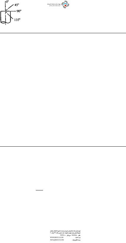
TABLE 5.12 Effect of Directivity Based on Angle to Direction of Flow and Size of Silencer Outlet
|
|
|
|
Octave band center frequency (Hz) |
|
|||||
Angle to direction |
Silencer outlet |
|
|
|
|
|
|
|
|
|
|
|
|
|
|
|
|
|
|
||
of flow |
diameter (in.) |
63 |
125 |
250 |
500 |
1000 |
2000 |
3000 |
4000 |
|
|
|
|
|
|
|
|
|
|||
0 |
72–96 |
þ4 |
þ5 þ5 þ6 |
þ6 |
þ7 |
þ7 |
þ7 |
|||
|
54–66 |
|
þ3 |
þ4 þ4 þ5 |
þ5 |
þ5 |
þ5 |
þ5 |
||
|
36–48 |
|
þ2 |
þ3 þ3 þ4 |
þ4 |
þ4 |
þ4 |
þ4 |
||
|
26–32 |
|
þ1 |
þ1 |
þ2 |
þ2 |
þ2 |
þ2 |
þ2 |
þ2 |
|
16–24 |
0 |
0 |
þ1 |
þ1 |
þ1 |
þ1 |
þ1 |
þ1 |
|
|
8–14 |
0 |
0 |
0 |
0 |
0 |
0 |
0 |
0 |
|
|
6 |
0 |
0 |
0 |
0 |
0 |
0 |
0 |
0 |
|
45 |
72–96 |
þ2 |
þ3 þ3 þ4 |
þ4 |
þ5 |
þ5 |
þ5 |
|||
|
54–66 |
|
þ1 |
þ2 þ2 þ3 |
þ3 |
þ3 |
þ3 |
þ3 |
||
|
36–48 |
0 |
þ1 |
þ1 |
þ2 |
þ2 |
þ2 |
þ2 |
þ2 |
|
|
26–32 |
0 |
0 |
0 |
þ1 |
þ1 |
þ1 |
þ1 |
þ1 |
|
|
16–24 |
0 |
0 |
0 |
0 |
0 |
0 |
0 |
0 |
|
|
8–14 |
0 |
0 |
0 |
0 |
0 |
0 |
0 |
0 |
|
|
6 |
0 |
0 |
0 |
0 |
0 |
0 |
0 |
0 |
|
90 and 135 |
72–96 |
1 |
2 5 7 |
10 |
12 15 17 |
|||||
|
54–66 |
0 |
1 |
2 |
5 |
8 |
10 |
13 |
16 |
|
|
36–48 |
0 |
0 |
1 |
3 |
6 |
7 |
11 |
15 |
|
|
26–32 |
0 |
0 |
0 |
1 |
3 |
5 |
9 |
14 |
|
|
16–24 |
0 |
0 |
0 |
0 |
1 |
3 |
7 |
13 |
|
|
8–14 |
0 |
0 |
0 |
0 |
1 |
2 |
5 |
11 |
|
|
5–6 |
0 |
0 |
0 |
0 |
0 |
1 |
3 |
6 |
|
|
4 |
0 |
0 |
0 |
0 |
0 |
0 |
1 3 |
||
Source: Burgess Manning.
A:
The volume of water in the drum must include the volume due to the straight section plus the dished ends.
Volume in the straight section, Vs, is given by
Vs ¼ L R2 57a:3 sin a cos a
where a is the angle shown in Fig. 5.5. The volume of liquid in each end is given by
Ve ¼ 0:261 H2 ð3R HÞ
Copyright © 2003 Marcel Dekker, Inc.
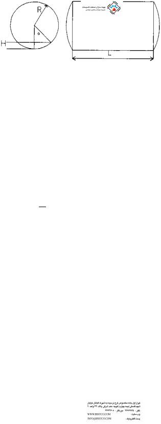
FIGURE 5.5 Partial volume of water in boiler drum.
where
H ¼ straight length of drum
R ¼ drum radius
In this case, H ¼ 120 in. and R ¼ 21 in.
Let us compute Vs1 and Ve1, the volume of the straight section and each end corresponding to the 19 in. level from the bottom of the drum.
cos a ¼ 212 ¼ 0:09523 Hence
a ¼ 84:5 and sin a ¼ 0:9954
vs1 |
¼ 120 21 21 |
84:53 |
0:0953 0:9954 |
|
|||
57:3 |
|||
|
¼ 73;051 cu in: |
|
|
Ve1 |
¼ 0:261 19 19 ð3 21 19Þ ¼ 4146 cu in: |
||
Hence total volume of liquid up to 19 in. level ¼ 73,051 þ 2 4146 ¼ 81,343 cu in. ¼ 47.08 cu ft.
Similarly, we can show that total |
volume of water up to the 15 in. |
||
level ¼ 34.1 cu ft. Hence the difference is 13 cu ft. |
|||
Specific volume of water at 400 psig ¼ 0.0193 cu ft=lb. |
|||
Normal evaporation rate ¼ 10;000 |
0:0193 |
|
|
|
|
|
|
60 |
|
||
¼ 3:2 cu ft=min
Hence the length of time between the levels assuming that the water supply has been discontinued ¼ 13=3.21 ¼ 4.05 min.
Copyright © 2003 Marcel Dekker, Inc.

NOMENCLATURE
A |
Area of opening, in.2, or duct cross section, ft2 |
A; B |
Factors used in Q5.26 |
BD |
Blowdown, fraction |
BHP |
Boiler horsepower |
cCorrosion allowance, in.
Cc |
Initial investment, $ |
Cd |
Coefficient of discharge |
Ce |
Cost of electricity, $=kWh |
Cp |
Specific heat, Btu=lb F |
dTube or outer diameter, in.
di |
Tube or pipe inner diameter, in. |
eEscalation factor
E Sealing efficiency, %; ligament efficiency, fraction F Factor defined in Eq. (33)
G Gas mass velocity, lb=ft2 h
hEnthalpy, Btu=lb
HHeight of liquid column, in.
hg; hf |
Enthalpy of saturated vapor and liquid, Btu=lb |
Hg |
Head of gas column, ft |
Hl |
Head of liquid, ft |
Hw |
Differential pressure across damper, in. WC |
i |
Interest rate |
LDistance, ft
LCC Life-cycle cost, $
MMoisture in air, lb=lb
MW Molecular weight
NAnnual period of operation, h
Pw |
Partial pressure of water vapor, psia |
P |
Gas pressure, psia; design pressure, psig |
DP |
Differential pressure, psi |
PWL |
Sound power level |
q |
Volumetric flow, gpm or cfm |
QEnergy, Btu=h
RRadius of drum, in.
RH Relative humidity
sSpecific gravity
Sa |
Allowable stress, psi |
SBV |
Steam by volume |
SPL |
Sound pressure level, dB |
SVP |
Saturated vapor pressure, psia |
Copyright © 2003 Marcel Dekker, Inc.

tFluid temperature, F
tw |
Minimum wall thickness of pipe or tube, in. |
TLife of plant, years
vSpecific volume, cu ft; subscripts g and f stand for saturated vapor and liquid
Ve; Vs |
Volume of drum ends, straight section, cu in. |
Vg |
Velocity of gas |
W |
Mass flow, lb=h |
xSteam quality
yVolume fraction
rDensity, lb=cu ft; subscript g stands for gas
REFERENCES
1.V Ganapathy. Determining operating parameters for hot exhaust gas cooling systems.
Plant Engineering, Mar 3, 1983, p 182.
2.V Ganapathy. Nomograph estimates steam leakage and cost. Heating Piping and AirConditioning, Nov 1982, p 101.
3.V Ganapathy. Quick estimates of damper leakage and cost energy loss. Oil and Gas Journal, Sept 21, 1981, p 124.
4.V Ganapathy. Applied Heat Transfer, Tulsa, OK: PennWell Books, 1982, p 186.
5.RJ Brown and RR Yanuck. Life Cycle Costing. Atlanta, GA: Fairmont Press, 1980, p 188.
6.ASME. Boiler and Pressure Vessel Code, Sec. 1. New York, 1980, p 119.
7.V Ganapathy. Estimate maximum allowable pressures for steel piping, Chemical Engineering, July 25, 1983, p 99.
8.ASME. Boiler and Pressure Vessel Code, Sec. 8, Div. 1, Para UG 131, 1980.
9.ASME. Boiler and Pressure Vessel Code, Sec. 1, Para PFT 51, 1989.
Copyright © 2003 Marcel Dekker, Inc.

6
Fuels, Combustion, and Efficiency of Boilers
and Heaters
6.01Estimating HHV (higher heating value) and LHV (lower heating value) of fuels from ultimate analysis; relating heat inputs based on HHV and LHV; relating boiler efficiencies based on HHV and LHV
6.02Estimating HHV and LHV of fuel oils if API is known
6.03Calculating cost of fuels on MM Btu (million Btu) basis; comparing electricity cost with cost of fuels
6.04Estimating annual fuel cost for power plants; relating heat rates with
|
efficiency of power plants |
6.05 |
Determining gas regulator settings for different fuels |
6.06 |
Correcting fuel flow meter readings for operating fuel gas pressures and |
|
temperatures |
6.07 |
Determining energy, steam quantity, and electric heater capacity required |
|
for heating air |
6.08Determining energy, steam quantity, and electric heater capacity required for heating fuel oils
6.09Combustion calculations from ultimate analysis of fuels; determining wet and dry air and flue gas quantities; volumetric analysis of flue gas on wet and dry basis; partial pressures of water vapor and carbon dioxide in flue gas; molecular weight and density of flue gas
6.10Combustion calculations on MM Btu basis; determining air and flue gas quantities in the absence of fuel data
Copyright © 2003 Marcel Dekker, Inc.
6.11Estimating excess air from flue gas CO2 readings
6.12Estimating excess air from CO2 and O2 readings; estimating excess air from O2 readings alone
6.13Effect of reducing oxygen in flue gas; calculating flue gas produced; calculating energy saved and reduction in fuel cost
6.14Effect of fuel heating values on air and flue gas produced in boilers
6.15Determining combustion temperature of different fuels in the absence of
fuel analysis
6.16a Calculating ash concentration in flue gases
6.16b Relating ash concentration between mass and volumetric units
6.17Determining melting point of ash knowing ash analysis
6.18Determining SO2 and SO3 in flue gases in lb=MM Btu and in ppm (volume)
6.19Determining efficiency of boilers and heaters; efficiency on HHV basis; dry gas loss; loss due to moisture and combustion of hydrogen; loss due to moisture in air; radiation loss; efficiency on LHV basis; wet flue gas loss; relating efficiencies on HHV and LHV basis
6.20Determining efficiency of boilers and heaters on HHV and LHV basis from flue gas analysis
6.21Loss due to CO formation
6.22Simple formula for efficiency determination
6.23Determining radiation losses in boilers and heaters if casing temperature and wind velocity are known
6.24Variation of heat losses and efficiency with boiler load
6.25a Sulfur dew point of flue gases
6.25b Computing acid dew points for various acid vapors
6.25c Effect of gas temperature on corrosion potential
6.25d Another correlation for sulfuric acid dew point
6.26a Converting NOx and CO from lb=h to ppm for turbine exhaust gases
6.26b Converting NOx and CO from lb=h to ppm for fired boilers 6.26c Converting UHC from lb=MM Btu to ppm
6.26d Converting SOx from lb=MM Btu to ppm
6.26e Converting NOx and CO from lb=h to ppm before and after auxiliary firing in an HRSG
6.26f Relating steam generator emission from measured oxygen value to 3% basis
6.27a Oxygen consumption versus fuel input for gas turbine exhaust gases 6.27b Determining gas turbine exhaust gas analysis after auxiliary firing 6.27c Determining turbine exhaust gas temperature after auxiliary firing
6.28Relating heat rates of engines to fuel consumption
Copyright © 2003 Marcel Dekker, Inc.

6.01
Q:
How are the HHV (higher heating value) and LHV (lower heating value) of fuels estimated when the ultimate analysis is known?
A:
We can use the expressions [1]
|
O2 |
|
|
HHV ¼ 14,500 C þ 62,000 H2 |
8 |
þ 4000 S |
ð1Þ |
LHV ¼ HHV 9720 H2 1110W |
|
|
ð2Þ |
where W is the fraction by weight of moisture in fuel, and C; H2; O2, and S are fractions by weight of carbon, hydrogen, oxygen, and sulfur in the fuel.
If a coal has C ¼ 0:80; H2 ¼ 0:003; O2 ¼ 0:005; W ¼ 0:073; S ¼ 0:006, and the rest ash, find its HHV and LHV. Substituting into Eqs. (1) and (2), we
have
HHV ¼ 14,500 |
0:80 þ 62,000 0:003 |
0: |
005 |
|
|
||||
|
8 |
|||
þ 4000 0:006 ¼ 11,771 Btu=lb |
|
|
||
LHV ¼ 11,771 |
9720 0:003 1110 0:073 |
|
||
¼ 11,668 |
Btu=lb |
|
|
|
Fuel inputs to furnaces and boilers and efficiencies are often specified without reference to the heating values, whether HHV or LHV, which is misleading.
If a burner has a capacity of Q MM Btu=h (million Btu=h) on HHV basis, its capacity on LHV basis would be
LHV |
ð3aÞ |
QLHV ¼ QHHV HHV |
Similarly, if ZHHV and ZLHV are the efficiencies of a boiler on HHV and LHV basis, respectively, they are related as follows:
ZHHV HHV ¼ ZLHV LHV |
ð3bÞ |
6.02a
Q:
How can we estimate the HHV and LHV of a fuel oil in the absence of its ultimate analysis?
Copyright © 2003 Marcel Dekker, Inc.
A:
Generally, the API of a fuel oil will be known, and the following expressions can be used:
HHV ¼ 17,887 þ 57:5 API 102:2 %S |
ð4aÞ |
||
LHV ¼ HHV 91:23 %H2 |
ð4bÞ |
||
where %H2 is the percent hydrogen by weight. |
|
||
2122:5 |
|
ð5Þ |
|
%H2 ¼ F |
|
|
|
API þ 131:5 |
|||
where |
|
||
F ¼ 24:50 for 0 API 9 |
|
||
F ¼ 25:00 for 9 API 20 |
|
||
F ¼ 25:20 for 20 API 30 |
|
||
F ¼ 25:45 for 30 API 40 |
|
||
HHV and LHV are in Btu=lb. |
|
||
6.02b
Q:
Determine the HHV and LHV of 30 API fuel oil in Btu=gal and in Btu=lb. Assume that %S is 0.5.
A:
From Eq. (4a),
HHV ¼ 17,887 þ 57:5 30 102:2 0:5
¼ 19,651 Btu=lb
To calculate the density or specific gravity of fuel oils we can use the expression
s ¼ |
141:5 |
¼ |
141:5 |
|
¼ 0:876 |
ð6Þ |
|||
|
|
|
|
|
|
||||
131:5 |
API |
131:5 |
þ |
30 |
|||||
|
|
þ |
|
|
|
|
|
|
|
Hence
Density ¼ 0:876 8:335 ¼ 7:3 lb=gal
8.335 is the density of liquids in lb=gal when s ¼ 1.
HHV in Btu/gal ¼ 19,561 7:3 ¼ 142,795
Copyright © 2003 Marcel Dekker, Inc.

From Eq. (5),
2122:5
%H2 ¼ 25:2 131:5 þ 30 ¼ 12:05
LHV ¼ 19,561 91:23 12:05 ¼ 18,460 Btu=lb
¼ 18,460 7:3 ¼ 134,758 Btu=gal
6.03a
Q:
A good way to compare fuel costs is to check their values per MM Btu fired. If coal having HHV ¼ 9500 Btu=lb costs $25=long ton, what is the cost in $=MM Btu?
A:
1 long ton ¼ 2240 lb. 1 MM Btu has 106=9500 ¼ 105 lb of coal. Hence 105 lb would cost
25
105 2240 ¼ $1:17=MM Btu
6.03b
Q:
If No. 6 fuel oil costs 30 cents=gal, is it cheaper than the coal in Q6.03a?
A:
Table 6.1 gives the HHV of fuel oils. It is 152,400 Btu=gal. Hence 1 MM Btu would cost
106
152,400 0:30 ¼ $1:96=MM Btu
6.03c
Q:
Which is less expensive, electricity at 1.5 cents=kWh or gas at $3=MM Btu?
A:
6 |
¼ |
1 kWh. At 1.5 cents=kWh, |
1 MM |
Btu of |
electricity |
costs |
3413 Btu |
|
|||||
(10 =3413) 1.5=100 ¼ $4.4. Hence in |
this case, |
electricity |
is costlier |
than |
||
gas. This example serves to illustrate the conversion of units and does not imply that this situation will prevail in all regions.
Copyright © 2003 Marcel Dekker, Inc.