

Учебное пособие 2134
.pdfRussian Journal of Building Construction and Architecture
––even in soils with low corrosiveness, the absence of ECP leads to the formation of galvanic pairs, that is, to the appearance of corrosion damage.
Use of new technologies and materials to improve the energy efficiency of the RCC and ensure the saving of electrical energy requires significant capital expenditures. At the same time, energy inspections of gas facilities carried out by JSC Giproniigaz indicate that other areas of energy efficiency improvement do not considerably reduce annual electricity consumption.
2. Performing corrosion inspection of objects. The survey is conducted in accordance with Guidelines (СТО) Gazprom 9.4-052-2016 “Organization of Corrosion Surveys of PJSC Facilities of Gazprom. Major Requirements”. The aim of the complex periodic corrosion survey is to assess the efficiency and increase the operational reliability of the PKZ system.
The survey tasks are the following:
––identifying the safety of an object in terms of length and time;
––identifying zones of negative influence of constant and alternating stray currents;
––specification of the location and classification of areas of various corrosion hazards also considering the results of diagnostics;
––identifying the technical condition of ECP facilities;
––local and integral assessment of the state of protective surfacings;
––optimization of operating modes of ECP facilities and designing recommendations for the operation of the ECP system;
––development of recommendations for repairs of ECP equipment and protective surfacings. Through the course of the survey, zones of increased corrosion hazard (ICH) are identified; the state of all electrical protection and control tools is evaluated, the safety of the site in terms of length and time is identified; based on the study the optimal operating modes of the ECP facilities are determined, recommendations for improving the operational reliability are provided; the places of insulation defects are identified; an integral assessment of the insulation of extended sections is performed, pipe insulation and pipeline metal in control pits is evaluated.
3. Problem of identifying the optimal distances between cathodic protection stations.
Analysis of the existing mathematical models of the ECP system made it possible to assume that by reducing the number of SCZs it is possible to cut down the total energy consumption for the operation of the ECP and at the same time to achieve complete protection of the pipeline with worn-out insulation.
Table 1 presents data on energy consumption (W, kWatt) for cathodic protection of gas pipelines 114×4 mm and 219×5 mm with a length of 100 km with an average integral transient
10
Issue № 2 (46), 2020 |
ISSN 2542-0526 |
insulation resistance R = 500 Ohm m2 depending on the distance between cathodic protection stations ΔL, km [19].
|
|
|
|
|
|
|
|
|
|
|
|
|
|
|
|
|
Table 1 |
|
|
|
Energy consumption for the cathodic protection |
|
|
|
|
|
|||||||||
|
|
|
|
|
|
|
|
|
|
|
|
|
|
||||
Energy con- |
|
|
Distance between the stations of the cathodic protection |
|
L, km |
|
|
||||||||||
sumption for |
|
|
|
|
|
|
|
|
|
|
|
|
|
|
|
|
|
the cathodic |
1 |
2 |
3 |
4 |
5 |
|
6 |
|
7 |
|
8 |
|
9 |
|
10 |
11 |
12 |
|
|
|
|
|
|
|
|
|
|
|
|
|
|
|
|
|
|
protection of |
|
|
|
|
|
|
|
|
|
|
|
|
|
|
|
|
|
the pipe- |
|
|
|
|
|
|
|
|
|
|
|
|
|
|
|
|
|
lines, W, |
|
|
|
|
|
|
|
|
|
|
|
|
|
|
|
|
|
kWatt |
|
|
|
|
|
|
|
|
|
|
|
|
|
|
|
|
|
|
|
|
|
|
|
|
|
|
|
|
|
|
|
|
|
|
|
|
|
|
|
pipeline |
114×4 mm |
|
|
|
|
|
|
|
|
||||
W114×4 |
|
|
|
0.092 |
|
0.12 |
|
0.14 |
|
0.165 |
|
0.225 |
|
|
|
|
|
0.06 |
0.065 |
0.075 |
0.083 |
|
|
|
|
|
|
|
|
||||||
|
|
|
|
pipeline |
|
219×5 mm |
|
|
|
|
|
|
|
|
|||
W219×5 |
|
|
|
|
0.16 |
|
0.195 |
|
0.23 |
|
0.27 |
|
0.33 |
|
0.41 |
|
|
0.115 |
0.125 |
0.133 |
0.15 |
|
|
|
|
|
|
|
|||||||
Table 2 shows the values of energy consumption for the cathodic protection of a Ø530×6 mm gas pipeline with a length of 100 km depending on the average integral transient insulation resistance and the distance between the cathodic protection stations.
|
Energy consumption for the cathodic protection of the pipelinesof 530х6 mm |
|
Tаble 2 |
||||||||||
Energy con- |
|
|
|||||||||||
|
|
Distance between the stations of the cathodic protection L, km |
|
|
|||||||||
sumption for |
1 |
2 |
3 |
4 |
5 |
6 |
7 |
8 |
9 |
10 |
11 |
12 |
|
the cathodic |
|||||||||||||
|
|
|
|
|
|
|
|
|
|
|
|
||
protection of |
|
|
|
|
|
|
|
|
|
|
|
|
|
the pipelines, |
|
|
|
|
|
|
|
|
|
|
|
|
|
W, kWatt |
|
|
|
|
|
|
|
|
|
|
|
|
|
|
|
Average integral transient resistance of the insulation R = 50 Ohm m2 |
|
|
|||||||||
W530×6 |
3.1 |
4.45 |
7.45 |
–– |
–– |
–– |
–– |
–– |
–– |
–– |
–– |
–– |
|
|
Average integral transient resistance of the insulation R = 100 Ohm m2 |
|
|
||||||||||
W530×6 |
1.41 |
1.72 |
2.32 |
3.45 |
5.12 |
–– |
–– |
–– |
–– |
–– |
–– |
–– |
|
|
Average integral transient resistance of the insulation R = 200 Ohm m2 |
|
|
||||||||||
W530×6 |
0.65 |
0.8 |
0.9 |
1.05 |
1.45 |
1.91 |
2.5 |
–– |
–– |
–– |
–– |
–– |
|
|
Average integral transient resistance of the insulation R = 500 Ohm m2 |
|
|
||||||||||
W530х6 |
0.27 |
0.29 |
0.31 |
0.37 |
0.47 |
0.49 |
0.51 |
0.57 |
0.64 |
0.77 |
0.98 |
–– |
|
Furthermore, by means of calculations, it is possible to identify the maximum permissible distance between the cathodic protection stations, which provides the required level of protective
11

Russian Journal of Building Construction and Architecture
potentials within the regulatory limits throughout the entire section of the underground pipeline. This distance decreases as does the diameter, transient insulation resistance and pipeline wall thickness.
Therefore, e.g., for a gas pipeline Ø 530×6 mm with a length of 100 km, the value of the maximum permissible distance between the CPS is 3.6 km (at R = 50 Ohm m2); 5.2 km (at R = 100 Ohm m2); 7.3 km (at R = 200 Ohm m2); 11.4 km (at R = 500 Ohm m2) [19].
The objective function of the task of identifying the optimal (maximum permissible) distances between cathodic protection stations (CPS), which provides the level of protective potentials within the normative limits throughout the entire pipeline section which are the integral costs in the construction and operation of stations, the optimality criterion is the minimum costs for calculated (specified) time period:
T |
1 |
|
|
З Эi cэi Kскз nскз скз 0 t |
|
, |
|
1 Е |
t |
||
t 0 |
|
|
where Эi is the annual energy consumption, kWatt h; сэi are the energy costs, rouble/(kWatt h);
Кскз are the capital costs of the cathodic stations including assembly, rouble/item; is the number of cathodic stations; 1 1Е t t is the discount coefficient; is the maintenance
costs of the station; скз is the percentage of annual costs of the station operation; Т is the life cycle of the system; t is the calculated life cycle of the system; 0, t is the coefficient of an increase in costs of resources for a year of the station construction at t = 0 and for a current year of operation t respectively; Е is the efficiency coefficient of the capital costs, year-1.
The more identical are CPS to each other, the lower the total energy consumption for the electrochemical protectionofthegas pipeline andthegreatertheintegralcostsare forthe CPSsystem.
4. Development of a viable layout of ECP facilities. The special feature of the location of underground gas pipelines of UGS facilities is their accuracy over a relatively small area. The presence of a large number of gas-collecting reservoirs and welling loops and their intersections are conducive to special conditions for the distribution of ECP funds in a more efficient manner.
There are two main scenarios for applying a viable scheme for placing ECP tools (or optimizing the operation of electrochemical protection tools by means of changing the original scheme):
— if the gas supply scheme under discussion consists of several underground pipelines designed in accordance to different projects where for one reason or another, it is not considered
12
Issue № 2 (46), 2020 |
ISSN 2542-0526 |
whether they belong to a single corrosion protection system or not, it is necessary to change the location of the ECP tools or points of input of the protection current depending on the state, saturation and mutual arrangement of pipelines;
— if the gas supply scheme under discussion contains “old” (operated for a long time) and newly built gas pipelines that require a different level of protective potential, it is essential to change the location of ECP tools or protection current input points according to the integral state of the insulation coating (depending on the type and life cycle).
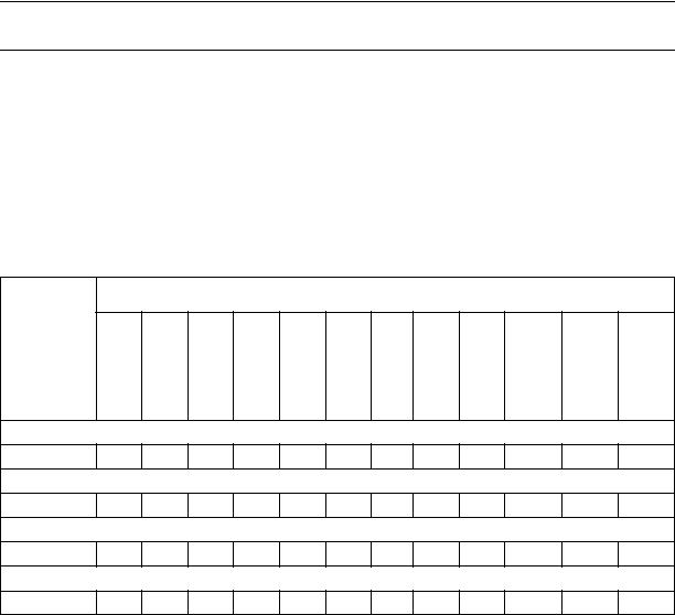
Let us look at an underground steel gas pipeline of an underground gas storage facility. A detailed examination shows that the gas-collecting collectors are located in parallel at a slight distance away. Thus, through the course of the reconstruction of the ECP system, it is possible to reduce the number of CPS by placing them at an equal distance from the adjoining gas pipelines. This will ensure that both of the pipelines are covered with a protective potential (Fig. 1).
а) |
b) |
Fig. 1. Location of ECP facilities prior and following the reconstruction on parallel gas pipelines: а) prior to the reconstruction of the ECP; b) following the reconstruction of the ECP;
1 are cathodic protection stations, 2 is a protective potential surfacing, 3 is an underground gas pipeline
Also, for underground gas pipelines of underground gas storages, intersection of welling loops is typical, which might pose extra difficulties when placing ECP facilities. This is most likely to occur where intersecting gas pipelines were laid at different times. In the case
13

Russian Journal of Building Construction and Architecture
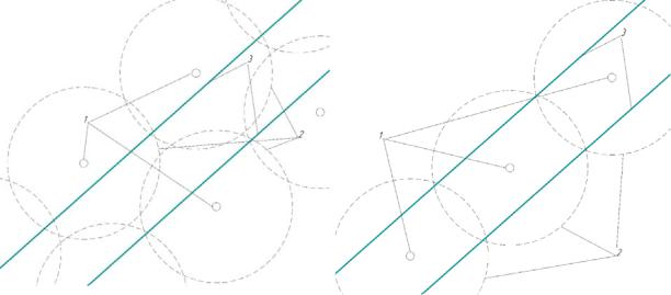
of reconstruction of ECP tools of such pipeline sections, the most viable way of placing ECP tools will be the installation of an ECP on the bisector of the intersection angle of the gas pipelines (Fig. 2).
а) |
b) |
Fig. 2. Location of ECP facilities prior to and following the reconstruction on the intersecting gas pipelines: a) prior to the reconstruction of ECP; b) following the reconstruction of the ECP; 1 are cathodic protection stations, 2 is a protective potential surfacing, 3 is an underground gas pipeline,
4 is a bisector of the angle of intersecting gas pipelines
Such an arrangement of ECP tools will not only reduce the number of CPS and thus the cost of capital costs and maintenance of the ECP facilities, but it also prevents hydrogen saturation of steel pipelines where the protective potentials of the adjoining cathodic protection stations overlap.
The practical implementation of the suggested algorithm was considered under the conditions of on-site technological networks of the compressor plant of the compressor station of the Yelshanskaya UGS compressor station. The optimization results are provided in the technical report of the complex periodic corrosion inspection of the facilities of the PJSC Gazprom [16]. In Fig. 3 are the results of a survey of one of the sections of the pipeline network.
According to the data of the report on the results of the corrosion survey, following the reconstruction of the ECP system and the reduction in the number of ECP stations, there is no hydrogenation of steel pipelines, while the required standards of pipeline protection are met.
14

Issue № 2 (46), 2020 |
ISSN 2542-0526 |
ofTypethe soil Specificof theelectricsoil, Ohmresistancem2 corrosiveAreashazardof Insulationtype Defectarea ProtectiveVpotential, TransientOhmresistance,m2
|
|
|
Transient resistance |
Left gradient |
|
|
|
|
|
|
Right gradient |
|
Protective potential, V |
|||||||
min (max) |
Power-off potential |
||||||
|
|
|
|
|
|
|
|
|
|
|
|
|
|
|
1 –– Small (of up to a two-fold increase in the signal), 2 –– medium (a two or four fold increase in the signal), 3 –– large (a four or more fold increase in the signal)
0 –– Moderate corrosive hazard, 1 –– Heightened corrosive hazard, 2 –– High corrosive hazard
|
|
High aggressiveness |
|
|
|
|
|
|
|
UGS |
|||
Medium aggressiveness |
Laying depth |
|||||
|
|
|
|
|
|
|
|
|
|
|
|
|
|
Output of the fuel and impulse treatment units
gradient, Potential
V
Length, km
gradient, Potential
V
Length, km
Length, km
Length, km
Length, km
m depth, Laying
Length, km
Length, km
Fig. 3. Corrosion map of the pipeline
Conclusions. The article analyzes and lists the major factors impacting the current consumption and power loss by the ECP system during the cathodic corrosion protection of gas distribution system objects.
The issues of reconstruction of the system of electrochemical protection of gas pipelines from the standpoint of energy efficiency are discussed. The on-site technological networks of the compressor plant of the Yelshanskayaundergroundgasstoragestationwereselected forinvestigation.
Practical measures are suggested in order to reduce the power losses of the ECP system. The above approach to designing a computational model of the ECP system made it possible to assume that as a result of the optimal location of CPS, more efficient protection of both newly
15

Russian Journal of Building Construction and Architecture
commissioned pipelines and those with worn-out insulation is achieved. At the same time, according to the results of measurements and verification calculation, the suggested principle of the location of ECP tools on parallel and intersecting gas pipelines allows one not only to reduce the cost of installation and operation of ECP tools, but also to prevent hydrogen saturation of the gas pipeline sections. Based on the results of the measurements of the average integral transient insulation resistance, it was argued that there is a maximum permissible distance between the cathodic protection stations making it possible to ensure the standard level of protective potentials throughout the entire section of the protected underground pipeline.
References
1.Aginei R. V., Aleksandrov Yu. V. Aktual'nye voprosy zashchity ot korrozii dlitel'no ekspluatiruemykh magistral'nykh gazonefteprovodov [Current issues of corrosion protection of long-term main gas and oil pipelines]. Saint Petersburg, Nedra Publ., 2012. 394 p.
2.BayasanovD.B.,BykovaZ.Ya.Raschet i proektirovanie gorodskikh gazovykh setei srednego i vysokogo davleniya
[Calculationanddesignofurbangasnetworksofmediumandhighpressure].Moscow,StroiizdatPubl.,1972.207p.
3.Iossel'Yu. Ya., Klenov G. E. Matematicheskie metody rascheta elektrokhimicheskoi korrozii i zashchity metallov [Mathematical methods for calculating electrochemical corrosion and metal protection]. Moscow, Metallurgiya Publ., 1984. 272 p.
4.Karnavskii E. L., Nikulin S. A. Obespechenie zashchishchennosti ob"ekta magistral'nogo transporta gaza za schet provedeniya kompensatsionnykh meropriyatii [Ensuring the security of the gas main transport facility through compensation measures]. Gazovaya promyshlennost', 2016, no. S737, pp. 14––18.
5.Kiselev V. G. Osnovnye printsipy proektirovaniya katodnoi zashchity podzemnykh metallicheskikh sooruzhenii [Basic design principles for cathodic protection of underground metal structures]. Nauchnotekhnicheskie vedomosti SPbGPU, 2011, no. 4, pp. 111––116.
6.Kravtsov V. V., Starochkin A. V., Blinov I. G. Kompleksnoe obsledovanie korrozionnogo sostoyaniya podzemnykh truboprovodov [Comprehensive inspection of the corrosion condition of underground pipelines]. Ufa, Ufim. gos. neft. tekhn. un-t Publ., 2012. 119 p.
7.Krivtsov A. O., Karnaukhov N. F. Apparatno-programmnyi kompleks upravleniya protivokorrozionnoi zashchitoi magistral'nogo truboprovoda [Hardware and software complex for controlling anti-corrosion protection of the main pipeline]. Vestnik DGTU, 2010, vol. 10, no. 6, pp. 881––889.
8.Lur'e M. V., Didkovskaya A. S., Varchev D. V., Yakovleva N. V. Podzemnoe khranenie gaza [Underground gas storage]. Moscow, Neft' i gaz Publ., 2004. 172 p.
9.Marukhin D. N., Osipova O. I., Pavlutin M. V. Sovremennye materialy i effektivnoe oborudovanie –– osnova nadezhnoi zashchity gazoprovodov ot korrozii [Modern materials and efficient equipment are the basis for reliable protection of gas pipelines from corrosion]. GAZ ROSSII, 2009, no. 1, pp. 38––41.
10.Maryanin V. V., Karnavskii E. L. Kontseptsiya sistemy korrozionnogo monitoringa ob"ektov gazotransportnoi sistemy [Concept of corrosion monitoring system for gas transmission system objects]. Korroziya «Territorii «NEFTEGAZ», 2016, no. 1, pp. 58––60.
16
Issue № 2 (46), 2020 |
ISSN 2542-0526 |
11.Pavlutin M. V., Petrov N. G., Vovk O. V. Elektrokhimicheskaya zashchita ot korrozii podzemnykh i podvodnykh metallicheskikh konstruktsii [Electrochemical corrosion protection of underground and underwater metal structures]. Moscow, SOPKOR Publ., 2017. 408 p.
12.Palashov V. V. Raschet polnoi katodnoi zashchity [Calculation of full cathodic protection]. Moscow, Nedra Publ., 1988. 136 p.
13.Podzemnoe khranenie gaza. Problemy i perspektivy [Underground gas storage. Problems and prospects]. Moscow, VNIIGAZ Publ., 2008. 477 p.
14.Smirnov V. A. Tekhniko-ekonomicheskoe obosnovanie skhem gazosnabzheniya [Feasibility study of gas supply schemes]. Moscow, Stroiizdat Publ., 1954. 220 p.
15.Sukharev M. G., Starovskii V. R. Rezervirovanie sistem magistral'nykh truboprovodov [Redundancy of trunk pipeline systems]. Moscow, Nedra Publ., 1987. 168 p.
16.Tekhnicheskii otchet GMP-GPKhG-TT-2346-UTPZ-TO-2019 po rezul'tatam kompleksnogo periodicheskogo korrozionnogo obsledovaniya ob"ektov, ekspluatiruemykh Elshanskim UPKhG OOO «Gazprom PKhG» [Technical report GMP-GPHG-TT-2346-UTPZ-TO-2019 on the results of a comprehensive periodic corrosion survey of facilities operated by the Elshansky UPKHG of Gazprom UGS LLC.]. Moscow, 2019. 358 p.
17.Tkachenko V. N. Metody rascheta i proektirovaniya elektrokhimicheskoi zashchity truboprovodnykh setei ot podzemnoi korrozii [Methods of calculation and design of electrochemical protection of pipeline networks from underground corrosion]. Moscow, VNIIOENG, dep.6.04.88, no. 1532-NG. 137 p.
18.Tkachenko V. N. Elektrokhimicheskaya zashchita truboprovodnykh setei [Electrochemical protection of pipeline networks]. Moscow, Stroiizdat Publ., 2004. 320 p.
19.Shuraits A. L., Pavlutin M. V., Zubailov G. I. Primenenie ratsional'noi skhemy razmeshcheniya sredstv elektrokhimicheskoi zashchity podzemnykh stal'nykh gazoprovodov ot korrozii [Application of a rational layout for electrochemical protection of underground steel gas pipelines from corrosion]. Neftegazovoe delo, 2009, vol. 7, no. 2, pp. 169––172.
20.Ashworth V., Booker C. J. L. Cathodic protection: theory and practice. Chichester, Published for the Institution of Corrosion Science and Technology, Birmingham, by Ellis Horwood. New York, Halsted Press, 1986. 357 p.
21.Brenna A., Lazzari L., Pedeferri Pia M., Ormellese M. Monitoring cathodic protection of buried pipeline by means of a potential probe with an embedded zinc reference electrode. Materials & Design, 2017, vol. 114,
pp. 194–201. https://doi.org/10.1016/j.matdes.2016.11.089.
22.Qian Shan, Cheng Frank Y. Accelerated corrosion of pipeline steel and reduced cathodic protection effectiveness under direct current interference. Construction and Building Materials, 2017, vol. 148, pp. 675–685. https://doi.org/10.1016/j.conbuildmat.2017.05.024.
23.Roberge P. R. Handbook of Corrosion Engineering. McGraw-Hill, New York, 1999. 1128 p.
24.Stears C. D., Moghissi O. C., Bone III L. Use of Coupons to Monitor Cathodic Protection of an Underground Pipeline. Materials Performance, 1998, no. 37 (2), pp. 23–31.
25.Wang Wenhe, Shen Kuiling, Yi Jun, Wang Qingsheng. A mathematical model of crevice corrosion for buried pipeline with disbonded coatings under cathodic protection. Journal of Loss Prevention in the Process Industries, 2016, vol. 41, pp. 270–281. https://doi.org/10.1016/j.jlp.2016.03.024.
17

Russian Journal of Building Construction and Architecture
TECHNOLOGY AND ORGANIZATION OF CONSTRUCTION
DOI 10.36622/VSTU.2020.2.46.002
UDC 639.86:004
E. P. Gorbaneva1, А. V. Mishchenko2
INFORMATION MODELING OF REAL ESTATE AT THE STAGE
OF SURVEY WORKS
Voronezh State Technical University1, 2
Russia, Voronezh
1PhD in Engineering, Assoc. Prof. of the Dept. of Technology, Organization of Construction, Expertise and Property Management, e-mail: egorbaneva@vgasu.vrn.ru
2Undergraduate of the Dept. of Technology, Organization of Construction, Expertise and Property Management, e-mail: mi9539@yandex.ru
Statement of the problem. Perform a review of scientific papers and regulatory documents used in information modeling. Explore information modeling technology at all stages of the life cycle of capital construction projects. Demonstrate the practical implementation of information modeling technology by the example of survey work.
Results. Deficiencies of the existing regulatory documents used in information modeling are identified. The tasks of information modeling technologies in the construction industry throughout the life cycle are formulated. The application of information modeling technology at the stage of engineering surveys of the life cycle of the capital construction object with the justification of its economic efficiency is considered.
Conclusions. For the effective application of information modeling technologies and ensuring the fulfillment of the tasks entrusted to it, it is necessary to create a full-fledged production regulatory framework that defines the status of the information model and the requirements for documentation received on its basis by various participants at all stages of construction production, as well as containing requirements for the storage of documents and making into her changes.
Keywords: information modeling, BIM-technologies, life cycle, engineering surveys, normative documentation, software systems, economic efficiency.
Introduction. Use of advanced information modeling technologies in construction in the territory of the Russian Federation is part of the national policy in the field of information technology application for various fields of activity and the overall “digitalization” of the economy.
© Gorbaneva E. P., Mishchenko А. V., 2020
18
Issue № 2 (46), 2020 |
ISSN 2542-0526 |
A particular feature of information modeling technologies at all stages of the life cycle of a construction object is the involvement in the process of designing a model, filling it with information and handling this information by a broad range of users in various fields of activity (builders, engineers,economists,maintenanceservices,etc.)aswell ashighinformationrichnessof themodel. Presently research is being actively carried out in certain areas of application of information modeling technologies in the construction industry [10, 11, 13]. A comprehensive assessment of the application of information modeling technologies is presented in a few studies [2, 5, 9, 17]. The most reliable are those that rely on the experience of practical application including overseas one [3, 6, 9, 16].
A key role is played by statistical research [1, 9, 19, 20, 21]. There are studies that describe a number of advantages of using information modeling technologies without critical assessment and substantiation [12] and are commercial. Some investigations are rather theoretical as their conclusions and outcomes do not allow for practical experience [2, 4, 7, 8, 12]. Most studies fail to provide objective performance indicators that can be compared or measured.
An assessment of compliance with regulatory requirements and the applied tools of practical implementation of information modeling technologies (software) as well as an assessment of their economic efficiency are not provided for any stage of the life cycle of an object.
Therefore it is becoming essential to study information modeling technology at all stages of the life cycle of major construction objects and demonstrate practical implementation of information modeling technology using the example of surveys.
1. Review of information modeling of construction objects. The process of designing and using information on completed construction projects as well as those in progress in order to coordinate input data, organize joint production and storage of data as well as to employ them for various purposes at all stages of the life cycle (section 3.10 of Construction Rules (СП) 333.1325800.2017) is internationally referred to as BIM (Building Information Modeling or Building Information Model).
The concept of information modeling of construction objects originated in the mid-80s with the emergence of computer technology and software. These systems were the first ones to ensure the functioning of complex automated facilities such as factory industrial complexes, large international airports, and nuclear power plants. Originally, these systems did not provide any explicit information about the structures and other building elements of the building and did not contain a virtual model of a building, but what they had was necessary information about engineering systems and automation to control their operation.
19