

Учебное пособие 2067
.pdfRussian Journal of Building Construction and Architecture
of positive temperatures, which completely excludes the use of technical butane even in the warm season.
The use of a gas-air mixture shifts the line of saturation of the vapor phase with moisture vapor, making it possible to take the vapor phase of butane from an underground tank at positive temperatures and transfer it with a decrease in temperature to negative numbers, bypassing the hydrate formation zone at any recommended level of butane content in the gas-air mixture.
This is central to why the use of gas-air mixtures for gas supply to consumers in a year-round operation mode is preferred.
3. Justification of the tank filling level with technical butane. In compliance with the rules for safe operation of liquefied petroleum gas tanks SP (СП) 62.13330.2011*, the recommendded level of filling with the liquid phase should not exceed 85%. This is due to the high coefficient of volumetric expansion when the gas is heated in the ground tank. In this case, the indicated filling level is presented in the calculation of the gas with a higher coefficient of volumetric expansion, i.e., propane. At the same time, in accordance with the GOST R (ГОСТ Р) 52087–2018, liquefied hydrocarbon gases are produced by about five main grades with different proportions of propane and butane. Thus, for gases based on butane, the tank at maximum heating will not be completely filled, which leads to ineffective use of the LPG tank. It should be noted that the filling level of ground and underground tanks must be assumed in the differentiated form due to different maximum heating temperatures. To calculate the volumetric expansion in surface tanks, the maximum temperature is taken as plus 55 ° C, for underground tanks –– plus 40°C [3]. Underground tanks, due to the lower temperature heating from the soil massif, can have a greater degree of filling.
In order to identify the degree of filling the reservoir with liquefied gas with an increased content of butane fractions, the state diagrams will be employed and a study will be conducted [3]. The time of the year has a considerable effect on the degree of filling the container with the liquid phase. Thus the dynamics of the degree of filling the tank with gas must be considered given the year-round use of the LPG tank.
The degree of filling the container is given by the ratio:
k |
|
= |
υt |
|
|
|
нр |
ж |
, |
(5) |
|||
υжt max |
||||||
|
|
|
|
where υжt is the specific volume of liquid at the moment of filling at the corresponding temperature of liquefied gas, m3/kg; υжt max is the specific volume of liquid at the maximum temperature of LPG heating in the tank, m3/kg [10].
50

Issue № 3 (47), 2020 |
ISSN 2542-0526 |
The specific volume of technical butane in a tank in a liquid state at any temperature is given by the expression:
υt |
= аυt |
+ bυt |
, |
(6) |
ж |
пр |
б |
|
|
where а, b is the content of propane and butane in liquefied petroleum gas, % (weight); υпрt ,
υбt is the specific volume of propane and butane liquid at the corresponding temperature at the moment of filling, m3/kg.
In order to identify the possible filling level of the tanks, calculations were performed for the ground and underground location of the LPG tanks for the gas composition corresponding to the GOST R (ГОСТ Р) 52087–2018 brand of technical butane. The LPG temperature at the time of filling the tanks varied from minus 100С to the maximum temperature with the appropriate location of the tanks [10].
The calculation results are shown in the graphs (Fig. 2).
Filling of the tank of the liquid phase, %
Maximumtemperature |
tank |
tank |
theheatingunderground |
Maximumtemperature theheatingunderground |
|
Recommended level of filling |
|
|
the tank |
|
|
|
of |
of |
Temperature of the liquefied hydrocarbon gas °С
Fig. 2. Justification of the filling level of the tanks:
1 is the underground tank filled with technical butane, 2 is the ground tank filled with technical butane
The analysis of the graphs (Fig. 2) showed that regardless of the composition of the liquefied gas and the initial initial temperature, the filling of the underground tank can be increased compared to the above-ground one. Thus, e.g., for a surface tank, the maximum filling level at a liquefied gas temperature of +20 °С is 89 %, and for an underground tank under similar
51

Russian Journal of Building Construction and Architecture
conditions, 95 % can be adopted. The difference in filling levels at different temperatures is from 4.7 % at a liquefied gas temperature of minus 10 °C to 15 % at a liquefied gas temperature of plus 40 °C.
This will make it possible to accommodate an additional 170 kg to 203 kg of technical butane per container with a volume of 5m3 as well as to increase the operating range of the container between neighboring gas stations while using gas fuel for the needs of heating, hot water supply and food preparation up to 3.5 days in the cold season and up to 20 days during the warm period for food preparation and hot water supply with no heating.
Conclusions
1.The composition of the butane-based gas-air mixture for gas supply to consumers should include 48––54 % butane and 52––46 % air, respectively. This composition complies with the condition of interchangeability of combustible gases and is within 5 % deviations in the Wobbe number.
2.The use of gas-air mixtures “butane-air” reduces the temperature of condensation of water vapor by 10 degrees or more in relation to the vapor phase of technical butane, which has a positive impact on gas consumption during the cold season.
3.While filling a liquefied gas tank, it is essential to employ a differentiated approach to the question of the degree of filling the tank with a liquid phase. The composition of the gas and placement of the container were found to have a considerable effect on the degree of filling. Considering the above factors makes it possible to increase the efficiency of gas supply systems while using technical butane providing an increased capacity of containers from 4.7 % at a liquefied gas temperature of minus 10 °C to 15 % at a liquefied gas temperature of plus 40 °C.
References
1.Bychkova I. M., Pobery A. A. K opredeleniyu koeffitsienta teploperedachi pri teploobmene gorloviny podzemnogo rezervuara s okruzhayushchim gruntovym massivom [To determine the heat transfer coefficient during heat exchange of the neck of an underground reservoir with the surrounding ground mass]. Resursoenergoeffektivnye tekhnologii v stroitel'nom komplekse regiona, 2018, no. 9, pp. 282––288.
2.Karasevich A. M., Yarygin Yu. N., Drozdov Yu. V. Rasshirenie istochnikov postavok gaza pri gazifikatsii regionov Rossii [Expansion of gas supply sources for gasification of Russian regions]. Gazovaya promyshlennost', 2009, no. 640, pp. 23––25.
3.Klimenko A. P. Szhizhennye uglevodorodnye gazy [Liquefied petroleum gas]. Moscow, Gostekhizdat Publ., 1962. 429 p.
52
Issue № 3 (47), 2020 |
ISSN 2542-0526 |
4.Kontseptsiya «Strategii sotsial'no-ekonomicheskogo razvitiya regionov Rossiiskoi Federatsii do 2020 goda»
[The concept of "Strategy of socio-economic development of the Russian Federation regions until 2020"].
5.Kuritsyn B. N., Medvedeva O. N. Tekhniko-ekonomicheskaya optimizatsiya sistem teplogazosnabzheniya
[Technical and economic optimization of heat and gas supply systems]. Saratov, 2011. 62 p.
6.Kuritsyn B. N., Usachev A. P., Shamin O. B. [Economic prerequisites for choosing a source of energy supply for buildings]. V mezhdunarodnyi s"ezd AVOK [V international Congress of AVOC]. Moscow, Izd-vo GP In- formrek-lamizdat, 1996, pp. 105––110.
7.Rid R., Prausnits Dzh., Shervud T. Svoistva gazov i zhidkostei [Properties of gases and liquids]. Leningrad, Khimiya Publ., 1982.
8.Sidorov R. I., Starikov A. N. Avtonomnoe gazosnabzhenie dlya chastnogo doma [Autonomous gas supply for a private home]. Academy, 2016, no. 1 (4), pp. 24––27.
9.Strategiya sotsial'no-ekonomicheskogo razvitiya Dal'nego Vostoka, Respubliki Buryatiya, Zabaikal'skogo kraya i Irkutskoi oblasti na period do 2025 goda: Utverzhdena rasporyazheniem Pravitel'stva Rossiiskoi Federatsii ot 28 dekabrya 2009 g. – №2094–r [The strategy of socio-economic development of the Far East, the Republic of Buryatia, the TRANS-Baikal territory and the Irkutsk region for the period up to 2025: Approved by decree of the Government of the Russian Federation No. 2094 – R of December 28, 2009].
10.Staskevich N. L., Vigdorchik D. Ya. Spravochnik po szhizhennym uglevodorodnym gazam [Handbook of liquefied petroleum gases]. – Leningrad, Nedra Publ., 1986. 543 p.
11.Tilicheev M. D. Fiziko-khimicheskie svoistva individual'nykh uglevodorodov [Physical and chemical properties of individual hydrocarbons]. Moscow – Leningrad, Gostoptekhizdat Publ., 1947,vyp. 2––4.
12.Bychkova I. M., Pobery A. A. To the determination of the coefficient of heat transfer during heat exchange of the neck of an underground reservoir with a surrounding soil massif. Resource-energy-efficient technologies in the construction complex: materials of the VI International. Scientific-practical. Conf. SSTU, 2018, pp. 282––288.
13.Costa F. C., Moutinho dos Santos E. Technical procedures for using synthetic natural gas as an Alternative to natural gas in different supply conditions for Industrial customers. Brazilian journal of petroleum and gas. Brazil, 2015, vol. 9, no. 2, pр. 037––044.
14.Durr C. A. 1984 Vapor Recovery from Liquid Hydrocarbon Storage Tank. Proceeding of 10th Gas Technology Conference. New York. pp 521––26.
15.Morge R. P., Yerazunis S. P. Heat and Mass Transfer during Liquid Evaporation form Porous Material. Heat Transfer with Phase Change, 1967, no. 63, pp. 1––7.
16.Muşat N-G., Munteanu V. Flame ignition and quenching of n-butane-air mixture at various initial pressures. Critical Properties. Bucharest. Rev. Roum. Chim, 2010, no. 55 (2), рр. 99–103.
17.Osipova N. N., Pobery A. A. Influence of unstable temperature of gaseous mixture of propane–butane on stable operation of autonomous gas supply systems with natural regasification. Scientific herald of the Voronezh State Architectural and Construction University. Series: Engineering systems of buildings and structures, 2017, no. 49 (68), pp. 69––78.
18.Osipova N. N., Bychkova I. M. M Application of gas-air mixtures for gas supply facilities. Sci and technical problems of improvement and development of gas-energy supply systems: materials of Intern. scientific-prac- tical. Conf. SSTU, 2018, pp. 17––19.
53

Russian Journal of Building Construction and Architecture
19.Thompson G. W. The Antoine equation for vapor-pressure date. Chemical Reviews, 1946, vol. 38, no. 1.
20.Usachev A. P., Shurayts A. L., Rulev A. V. and Pavlutin M. V. Development of the equation of thermal balance of the horizontal pipe heat exchanger of the ground heat pump. Sci and technical problems of improvement and development of gas–energy supply systems: materials of Intern. Scientific-practical. Conf. SSTU, 2017, pp. 146––151.
21.Worasaen A., Pannucharoenwong N., Benjapiyaporn C., Jongpluempiti J. Suitable Study of CBG Fuel by Considering in Wobbe Index From Compressed Bio-Methane Gas Plant. Energy Procedia, 2017, vol. 138, рр. 278––281.
54

Issue № 3 (47), 2020 |
ISSN 2542-0526 |
BUILDING MATERIALS AND PRODUCTS
DOI 10.36622/VSTU.2020.47.3.005
UDC 539.21
B. M. Kumitskiy1, N. A. Savrasova2, V. N. Melkumov3, Ye. S. Aralov4
MATHEMATICAL MODELING OF COLD PRESSING THE SHEET COMPOSITE
Voronezh State Technical University1, 3, 4
Russia, Voronezh
Military Training and Scientific Center of the Air Force
“Air Force Academy Named after Prof. N. Ye. Zhukovsky and Yu. A. Gagarin”2 Russia, Voronezh
1PhD in Physics and Mathematics, Assoc. Prof. of the Dept. of Heat and Gas Supply and Oil and Gas Business, tel.: +7-999-401-60-87, e-mail. boris-kum@mail.ru
2PhD in Physics and Mathematics,, Assoc. Prof. of the Dept. of Physics and Chemistry, tel.:+7-951-872-94-25, e-mail: savrasova-nataly@mail.ru
3D. Sc. in Engineering, Prof. of the Dept. of Heat and Gas Supply and Oil and Gas Business, tel.: (473)271-53-21, e-mail: teplosnab_kaf@vgasu.vrn.ru
4PhD student of the Dept. of Heat and Gas Supply and Oil and Gas Business, tel.:+7-960-125-29-96, e-mail: vgtu.aralov@yandex.ru
Statement of the problem. The article examines the problem of cold pressing, which is the most important technological component in the production of sheet composite, which is widely studied in the repair and construction works in the interior decoration of residential and industrial premises. The solution to this problem is carried out on the basis of a physical and mathematical model under the assumption that the rheological properties of the deformable medium correspond to the principles of ideal plasticity and a flat deformable state. Within the framework of the problem, in two dimensions of quasistatic compression between absolutely rigid parallel-approaching plates of a thin ideally plastic layer, the stress-strain state of a composite medium is studied. It is believed that in the absence of volumetric loads, the condition of incompressibility of the medium and the associated flow law is fulfilled. Based on the hypothesis of the linear distribution of tangential stresses over the thickness of the deformable layer, analytical expressions for the statistical and kinematic characteristics of the deformation are obtained, and the condition at the edges of the rough plates makes it possible to determine the coefficient of slip thorns, which makes it possible to control the pressing process.
Results and conclusions. It was established that the components of the strain rate are directly proportional to the plate approach speed, and the normal stresses acting in the pressing direction are independent of the loading speed, decreasing in magnitude from the center to the periphery.
Keywords: yield strength, pressing, plasticity condition, mathematical model.
Introduction. The development and improvement of modern building technologies, aviation industry and electronics cannot be conceived without the use of new construction materials including composites in particular [3, 8, 13, 14].
© Kumitskiy B. M., Savrasova N. A., Melkumov V. N., Aralov Ye. S., 2020
55

Russian Journal of Building Construction and Architecture
A composite is a structural material consisting of several components: a matrix (binder) and a reinforcing medium (filler) in the form of threads, fibers, particles, etc. The mechanical behavior of composites is given by the ratio of the properties of the reinforcing elements and the matrix, as well as the bond strength between them.
Methods for designing new composite materials and investigating the stress-strain state in the process of pressing them is an urgent problem of mechanics of a deformable solid [13]. The first step to solving any problem suitable for practical research is commonly the development of a physical and mechanical model that allows for multifunctional analysis and selection of the optimal strategy for conducting the technological process [8, 15].
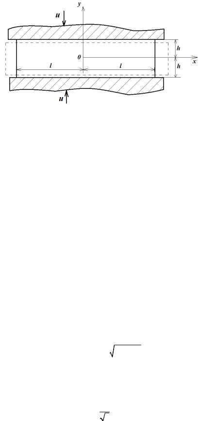
To date, a number of mathematical models have been developed that describe the processes occurring under the conditions of pressing composite materials [3, 10, 14]. A mathematical model is set forth that describes the processes occurring in a viscous incompressible fluid located in a thin layer between parallel planes moving towards them. The parameters of the stress-strain state obtained in this case make it possible to control the pressing process of plywood and other laminated plastics [10, 15]. The results of theoretical and experimental studies of the process of powder materials in the conditions of self-propagating high-temperature synthesis were previously presented [3,8]. A model based on the fundamental laws of conservation of mass, momentum and energy, within the framework of the mechanics of a deformable solid under conditions of wood pressing considering anisotropy was suggested in [6]. The results of modeling the process of flat pressing of plates from wood waste and thermoplastics were obtained in [11, 12, 13] where a qualitative assessment of the temperature across the thickness of the plates, degree of solidification of the thermoplastic as well as normal and tangential stresses at the interface was performed. The above analysis of these and other known models [9, 16, 18] shows that most of them describe the behavior of the bonding agent under pressing conditions without affecting the base material. In addition, the suggested models are based on the viscous and elastic properties of the medium which do not fully correspond to actual materials. The purpose of the study is to develop a mathematical model that within the framework of a deformable solid and the equations of ideal plasticity potentially describe the rheological properties of a composite material under conditions of cold flat pressing. The solution to this problem is presented in accordance with the methodology [7] on the example of semi-dry pressing of gypsum plates (GP). 1. Methods of mathematical modeling. First let the space between two rigid rough parallel plates moving towards each other at a constant velocity u be filled with a composite material whose the rheological properties correspond to the ideal plasticity model [7]. A schematic diagram of the deformation of the medium is presented in Fig. 1.
56
Issue № 3 (47), 2020 |
ISSN 2542-0526 |
Fig. 1. Compression of a thin layer of a composite sample between the approaching plates (-l < x < l; y = ±h)
Let us assume that the flow plane of the medium in question is determined by the plane (x, y), there are no volumetric forces and the velocity u of the closure of the plates is insignificant. Neglecting elastic deformations provided that all quantities do not depend on z, let us consider a plastic flow in two dimensions [17].
Then the equilibrium equations are as follows:
∂σ |
x + |
∂τxy |
= 0, |
(1) |
|
|
∂y |
||||
∂x |
|
|
|||
∂τxy |
+ |
∂σ y |
= 0, |
(2) |
|
|
∂y |
||||
∂x |
|
|
|||
where σx, σy, τxy are the stress components related to the axes x, y.
Differentiating (1) and (2) for the second time with subsequent subtraction and using the von Mises plasticity condition [1, 4, 13]
1 |
(σx − σ y )2 |
+ τxy |
2 |
= k2 , |
(3) |
4 |
|
|
|
|
|
we obtain the following expression:
2 |
|
2 |
|
|
2 |
|
2 |
2 |
|
|
|
|
∂ |
|
( |
k |
− τ xy ) |
|
|
||
∂ τxy |
− |
∂ τxy |
= ±2 |
|
. |
(4) |
||||
|
∂y2 |
|
|
|
∂x∂y |
|||||
∂x2 |
|
|
|
|
|
|
||||
Here k is the yield stress equal to the maximum value of the shear stresses which for the Mises yield condition takes the value
k = σ30 ,
where σ0 is the material constant.
57

Russian Journal of Building Construction and Architecture
We will search for a solution (4) where the stress τxy is a function that depends only on y. In this case, it will be as follows:
|
∂2τ |
|
|
|
|
xy |
= 0, |
(5) |
|
|
∂y2 |
|||
|
|
|
|
|
which is a linear function [7]: |
|
|
|
|
τxy = − ky |
, |
(6) |
||
|
|
h |
|
|
with the boundary conditions τxy = ± k at y = h. This corresponds to the state of flow of a deformable medium along the contact plane to the right.
Considering that the differential equilibrium equations (1) and (2) are as follows:
∂σx = k , ∂x h
(7)
∂σ y = 0, ∂y
whose integration yields:
σx = kh x + F(y),
(8)
σ y = G(x),
where F(y) and G(x) are arbitrary functions identified from the plasticity condition (3) which considering (6) can be written as:
F( y) − G(x) + |
kx |
= ±2k 1− |
y2 |
. |
(9) |
|
h |
h2 |
|||||
|
|
|
|
Since the equation (9) is satisfied for any values of x and y, the following relations are valid for F(y) and G(x):
F( y) = −P ± 2k 1− |
y2 |
, |
(10) |
||
h2 |
|||||
|
|
|
|
||
G(x) = −P + kx |
, |
|
|
(11) |
|
h |
|
|
|
|
|
where P is an arbitrary constant. Under this condition, the expressions (8) are satisfied by two stress systems of this type:
σ |
|
= −P + |
kx |
± 2k 1 |
− |
y2 |
, |
(12) |
|
x |
h |
h2 |
|||||||
|
|
|
|
|
|
||||
|
|
σ y = −P + kx . |
|
|
|
(13) |
|||
|
|
|
|
h |
|
|
|
|
|
58
Issue № 3 (47), 2020 |
ISSN 2542-0526 |
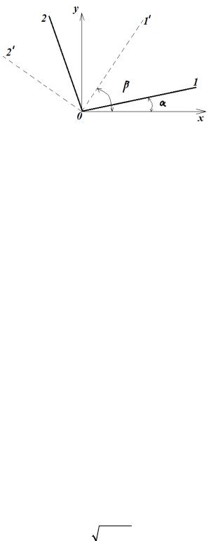
In order to identify the distribution of velocities corresponding to the stresses (6), (12), (13), it is necessary that we determine the trajectory of the slip lines [2, 15]. For that, we assume that the principal axes are generally inclined at the angle α and α+π/2, n it is obvious that the shear directions will be inclined to it at the angles β and β ± π/2 where β=α+π/4 (Fig. 2).
Fig. 2. General case of the mutual location of the axis coordinates (x, y), directions of the main axes (1, 2) and shear axes (1’, 2’)
Using the known equations
σ0 = 12 (σ1 + σ2 ) and σ1 − σ2 = 2k
and replacing α by (β - π/4), the stress components (12), (13) and (6), respectively, can be the following taking into account only the positive sign of the stress (12):
σx = σ0 + k sin 2β,
σ y = σ0 − k sin 2β,
τxy = −k cos 2β.
Then the differential equations of two systems of slip lines will be written:
dx |
= tgβ = |
1− cos 2β |
= |
2(k + τxy ) |
, |
||||
dy |
sin 2β |
|
σx − σ y |
||||||
|
|
|
|
|
|||||
|
dy |
= −ctgβ = − |
|
σx − σ y |
|
||||
|
dx |
|
. |
|
|||||
|
2(k + τxy ) |
|
|||||||
(14)
(15)
(16)
Substituting the stress components (6), (12), (13) into (15), we obtain differential equations for a system of the slip lines:
dy |
= − |
h − y |
, |
(17) |
|
dx |
h2 − y2 |
||||
|
|
|
59