

Учебное пособие 1751
.pdf(SNR), measured in decibels (dB). The higher the SNR, the better the signal quality. Interference may be inadvertent, as in the case of the pilot’s call to the tower. Or, it may be a deliberate attempt on the part of an adversary to disrupt an operator’s ability to communicate.
2.Engineers use various techniques to combat noise and interference, including: (1) boosting the effective radiated power, (2) providing a means for optimizing operating frequency, (3) choosing a suitable modulation scheme, (4) selecting the appropriate antenna system, and (5) designing receivers that reject interfering signals. Let’s look at some of the more common causes of noise and interference.
3.Lightning is the main atmospheric (natural) source of noise. Atmospheric noise is the highest during the summer and greatest at night, especially in the 1- to 5-MHz range. Average values of atmospheric noise, as functions of time of day and season, have been determined for locations around the world, and are used in predicting HF radio system performance. Another natural noise source is galactic or cosmic noise, generated in space. It is uniformly distributed over the HF spectrum, but does not affect performance below 20 MHz.
4.Power lines, computer equipment, and industrial and office machinery produce man-made noise, which can reach a receiver through radiation or by conduction through power cables. This type of man-made noise is called electromagnetic interference (EMI) and it is the highest in urban areas. Grounding and shielding of the radio equipment and filtering of AC power input lines are techniques used by engineers to suppress EMI.
5.At any given time, thousands of HF transmitters compete for space on the radio spectrum in a relatively narrow range of frequencies, causing
interference with one another. Interference is most severe at night in the lower bands at frequencies close to the MUF. The HF radio spectrum is especially congested in Europe due to the density of the population.
6. A major source of unintentional interference is the collocation of transmitters, receivers, and antennas. It’s a problem on ships, for instance, where space limitations dictate that several radio systems be located together. For more than 30 years, Harris RF Communications has designed and implemented high-quality integrated shipboard communications systems that eliminate problems caused by collocation. Ways to reduce collocation interference include carefully orienting antennas, using receivers that won’t overload on strong, undesired signals, and using transmitters that are designed to minimize intermodulation.
41
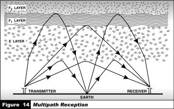
7. Deliberate interference, or jamming, results from transmitting on operating frequencies with the intent to disrupt communications. Jamming can be directed at a single channel or be wide band. It may be continuous (constant transmitting) or look-through (transmitting only when the signal to be jammed is present). Modern military radio systems use spread-spectrum techniques to overcome jamming and reduce the probability of detection or interception. Spread-spectrum techniques are techniques in which the modulated information is transmitted in a bandwidth considerably greater than the frequency content of the original information. Signals from a transmitter reach the receiver via multiple paths (figure 14). This causes fading, a variation in average signal level because these signals may add or subtract from each other in a random way.
Task 45. Fill in the gaps with the correct variants:
1. Receiver ………… and interference come from both external and internal sources.
a) |
signal |
b) noise |
c) grounding |
|
2. |
External noise …......... greatly exceed internal receiver noise over |
|||
much of the HF band. |
|
|
||
a) receiver |
b) level |
c) sources |
||
3. |
Lighting in the main …… of noise. |
|||
a) interference |
b) source |
|
c) level |
|
42
4. Power lines, computer equipment industrial and office machinery produce …….. noise.
a) natural b) artificial c) man made
5. Grounding and ………… of the radio equipment and filtering of AC power input lines are techniques used by engineers to suppress EMI.
a) each |
b) shielding |
c) collocation |
Task 46. Match up given titles to each paragraph of the TEXT 2.1:
1.Quality of a signal.
2.Various techniques to combat noise and interference.
3.Atmospheric noise.
4.Electromagnetic interference.
5.Collocation of transmitters.
6.Space noise.
7.Spread-spectrum techniques used to overcome jamming.
Task 47. Organizing your thoughts.
1.Where do receiver noise and interference come from?
2.What is a signal-to-noise ratio (SNR)?
3.What techniques do engineers provide to combat noise and interference?
4.When is the atmospheric noise highest?
5.How is man-made noise produced?
6.What do you know about unintentional interference?
7.What is a major source of unintentional interference?
8.What are the ways to reduce collocation interference?
9.What are the spread-spectrum techniques aimed at?
10.Why do radio engineers use spread-spectrum techniques in modern military radio systems?
Task 48. Sum up the TEXT 2.1 using the following plan:
1.External noise level.
2.Natural noise.
3.Interference and its problems.
4.Collocation problems.
43

ACTIVITY 2
Text 2.2: ELEMENTS OF RADIO SYSTEMS
Grammar: COMPOSITION OF NOUNS
Task 49. Form nouns of the following verbs:
a)verb + er, ier → noun
to transmit – transmitter to amplify –
to transceive – to ractify –
to transform – to receive – to control –
b)verb + tion → noun
to communicate – communication to demodulate –
to absorb –
c)verb + ment → noun
to develop – development to equip –
Task 50. Find nouns in the following English sentences. Pay attention to how they are formed.
1.The primary components in the HF radio systems fall into the groups: transmitters, receivers and antennas.
2.The resulting signal is converted to the frequency that is to be transmitted.
3.This process reduces interference with adjacent communications channels.
4.Receivers select a desired signal, amplify it to a suitable level.
5.At present lots of functions are performed digitally.
44
6. The filtered signal is converted to another frequency for further processing.
Task 51. Skim the following text and try to understand the subject-matter of the text.
TEXT 2.2:
ELEMENTS OF RADIO SYSTEMS
1.Now that you have an overview of how radio waves propagate, let’s take a look at how they are generated. The primary components in an HF radio system fall into three groups: transmitters, receivers, and antennas. In many modern radio sets, the transmitter and receiver are contained in a single unit called a transceiver. In large, fixed systems, transmitting stations and receiving stations are customarily positioned at separate locations, often controlled from a remote third site.
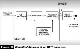
2.Although transmitters may vary widely in their configuration, they all consist of an exciter and power amplifier. A simplified diagram of a typical HF transmitter is shown in Figure 15.
3.The exciter synthesizes a carrier, which has one of its properties – amplitude, frequency, or phase – modified (modulated) by a lower frequency signal derived from a source of information such as a microphone. The resulting signal is converted to the frequency that is to be transmitted. The power amplifier boosts the output power of the signal to the desired wattage for transmission before sending it through a cable to the transmitting antenna.
4.The transmitter may also contain filters that are used to ”clean up” its
45
output. A bandpass filter removes noise, spurious signals, and harmonics generated in the exciter, or output frequency harmonics coming from the power amplifier. This process reduces interference with adjacent communications channels.
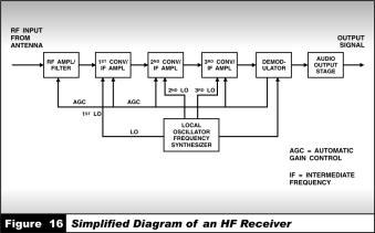
5. All modem HF receiving systems include an RF input filter/ amplifier, a series of frequency converters and intermediate frequency (IF) amplifiers, a demodulator, and a local oscillator frequency synthesizer (see figure 16). To function, the receiver selects a desired signal, amplifies it to a suitable level, and recovers the information through the process of demodulation, in which the original modulating signal is recovered from a modulating carrier. With contemporary radio equipment, many of these functions are performed digitally.
6.In order to filter out noise and undesired signals, the RF input stage sometimes incorporates a tunable preselector (a bandpass filter). The filtered signal is then amplified and converted to another frequency for further processing.
7.But the filtering process does not end here. Typically, the received signal is filtered and amplified again at several different intermediate frequencies. The amplification provided in these stages is a variable that depends on the strength of the received signal.
8.In order to output voice or data, for example, the demodulator produces an audio-frequency (base-band) signal that interfaces with additional equipment. Also, because the strength of the input signal may not be constant, the demodulator stage produces a voltage proportional to the level of the RF input signal. To compensate for changes in the
46
signal, the voltage is fed back to the RF and IF amplifiers for automatic gain control (AGC), to maintain a constant input to the demodulator. Task 52. Comprehension check:
1.What are the primary components in HF radio systems?
2.What does a transmitter consist of?
3.Does the power amplifier boost the output power of the signal to the desired wattage for transmission?
4.What is a resulting signal?
5.What are the transmitter filters used for?
6.To function, the receiver selects a desired signal, amplifies it to a suitable level, and recovers the information through the process of demodulation, doesn't it?
7.What is a tunable preselector used for?
8.Which function does a demodulator perform?
Task 53. Match up the words with the definition:
to transmit |
Free transmission range |
|
|
exciter |
to get; to pick up a signal |
|
|
amplifier |
to transduce |
|
|
bandpass |
telecommunication provider |
|
|
to receive |
a device of increasing activity; feed element |
|
|
to convert |
a device for increasing strength |
|
|
|
|
carrier |
to transfer signals from one place to another |
|
|
47
ACTIVITY 3
Text 2.3: ANTENNA CHARACTERISTICS AND
PARAMETERS
Grammar: MODAL VERBS
Task 54. Study the meaning of English modal verbs in sentences.
Modal verbs |
EXAMPLE |
|
|
|
|
Can/may |
Some antennas can provide a 50-ohm load to |
|
(мочь, |
the transmitter. Maximum power may be |
|
возможно |
transferred from the transmitter. |
|
удастся) |
|
|
Must |
Radio users must understand the radiation |
|
(должен, |
||
pattern of an antenna. |
||
обязан) |
||
|
||
Should |
For ground ware propagation, the transmitting |
|
and receiving antennas should have the same |
||
(должен, |
||
polarization for best results. |
||
следует) |
||
|
||
|
|
Task 55. Find sentences with modal verbs in the English Sentences. Pay attention to their Russian equivalent.
1. The basic challenge in radio |
Основной проблемой радиосвязи |
communications is to get the most |
является получить наибольшую |
power possible, that you may need |
мощность, которая возможно вам |
to transmit signals. |
потребуется для передачи сигналов. |
|
|
2. Antennas can be connected |
Антенны могут быть подсоединены |
directly to the transmitter. |
непосредственно к передатчику. |
|
|
3. Radio users must understand |
Радиопользователи должны |
the radiation pattern of an |
понимать диаграмму |
antenna for optimal original |
направленности излучения |
transmission. |
антенны для оптимальной |
|
передачи сигнала. |
4. Polarization of the antenna |
Поляризация антенн не должна |
need not be the same. |
быть одинаковой. |
|
|
|
48 |
Task 56. Skim the following text and understand its subjectmatter:
TEXT 2.3:
ANTENNA CHARACTERISTICS AND PARAMETERS
1.Some of the most commonly used terms to describe antennas are impedance, gain, radiation pattern, take-off angle, and polarization.
2.Every antenna has an input impedance, which represents the load to be applied to the transmitter. This impedance depends upon many factors, such as antenna design, frequency of operation, and location of the antenna with respect to surrounding objects.
3.The basic challenge in radio communications is finding ways to get the most power possible, where and when you need it, to generate and transmit signals. Most transmitters are designed to provide maximum output power and efficiency into a 50-ohm load. (OHM is a unit of measurement of resistance. Its symbol is Ω) Some antennas, such as log periodic antennas, can provide a 50-ohm load to the transmitter over a wide range of frequencies. These antennas can generally be connected directly to the transmitter. Other antennas, such as dipoles, whips, and long-wire antennas, have impedances that vary widely with frequency and the surrounding environment. In these cases, an antenna tuner Ohm coupler is used. This device is inserted between the transmitter and antenna to modify the characteristics of the load presented to the transmitter so that maximum power may be transferred from the transmitter to the antenna.
4.The gain of an antenna is a measure of its directivity – its ability to focus the energy it radiates in a particular direction. The gain may be determined by comparing the level of signal received from it against the level that would be received from an isotropic antenna, which radiates equally in all directions. Gain can be expressed in dB; the higher this number, the greater the directivity of the antenna. Transmitting antenna gain directly affects transmitter power requirements. If, for example, an omnidirectional antenna was replaced by a directional antenna with a gain of 10 dB, a 100-watt transmitter would produce the same effective radiated power as a 1-kW transmitter and omnidirectional antenna.
5.In addition to gain, radio users must understand the radiation pattern of an antenna for optimal signal transmission. Radiation pattern is determined by an antenna’s design and is strongly influenced by its location with respect to the ground. It may also be affected by its proximity to nearby objects such as buildings and trees. In most
49
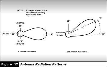
antennas, the pattern is not uniform, but is characterized by lobes (areas of strong radiation) and nulls (areas of weak radiation).
These patterns are generally represented graphically in terms of plots in the vertical and horizontal planes (figure 17), which show antenna gain as a function of elevation angle (vertical pattern) and azimuth angle (horizontal plot). The radiation patterns are frequency dependent, so plots at different frequencies are required to fully characterize the radiation pattern of an antenna.
6.In determining communications range, it is important to factor in the take-off angle, which is the angle between the main lobe of an antenna pattern and the horizontal plane of the transmitting antenna. Low take-off angles are generally used for long-haul communications; high take-off angles are used for shorter-range communications.
7.For ground wave propagation, the transmitting and receiving antennas should have the same polarization for best results. For sky wave propagation, the polarization of the antennas need not be the same, since the polarization of the signal will change during ionospheric refraction.
Task 57. Study the following sentences. Cover one part and translate from Russian into English, from English into Russian. Check up:
50