

всё о микросхемах / app_n_termistor
.pdfApplication Notes
1 Application notes
As to their possibilities of application, PTC thermistors can be divided in the following manner:
a) by function
Directly |
heated PTC thermistor |
Indirectly heated PTC thermistor |
|
|
|
Heat is generated in the |
|
|
|
|
|
|
|
|
|
|
||
|
|
|
|
Heat is supplied from outside |
|
|
||||||
|
PTC thermistor |
|
|
|
|
|
|
|||||
|
|
|
|
|
|
|
|
|
|
|
||
|
|
|
|
|
|
|
|
|
|
|
|
|
|
|
|
|
|
|
|
|
|
|
|
|
|
|
|
|
|
|
|
|
|
|
|
|
||
Power PTC thermistors |
|
|
|
|
|
|
PTC |
temperature sensors |
|
|
||
|
|
|
|
|
|
|
||||||
|
|
|
|
|
|
|
|
|
|
|
|
|
|
|
|
|
|
|
|
|
|
|
|
|
|
Applications where the electrical resistance |
|
Applications where the electrical resistance |
|
|||||||||
is primarily determined by the current passing |
|
is primarily determined by the temperature of the |
|
|||||||||
|
||||||||||||
through the thermistor. |
|
medium surrounding the thermistor. |
|
|||||||||
b) by application |
|
|
|
|
|
|
|
|
|
|
|
|
|
|
|
|
|
|
|
|
|
|
|
|
|
Power PTC thermistors |
|
Sensors |
|
|
|
|||||||
|
|
|
|
|
|
|
|
|
|
|
|
|
Fuse |
Short-circuit and |
|
Temperature |
Overtemperature protection |
|
|||||||
|
overcurrent protection |
|
|
|
|
|
Measurement and control |
|
||||
|
|
|
|
|
|
|
|
|
|
|
|
|
Switch |
Motor start |
|
Limit temperature |
|
|
|
||||||
|
Degaussing |
|
|
|
|
|
Motor protection |
|
||||
|
Switching |
|
|
|
|
|
Overtemperature protection |
|
||||
|
|
|
|
|
|
|
|
|
|
|
|
|
Heater |
Small heaters |
|
|
|
|
|
|
|
|
|||
|
Thermostats |
|
|
|
|
|
|
|
|
|||
|
|
|
|
|
|
|
|
|
|
|
|
|
Level sensor |
Limit indicators |
|
|
|
|
|
|
|
|
|||
|
|
|
|
|
|
|
|
|
|
|
|
|
1.1PTC thermistors for overcurrent protection
Ceramic PTC thermistors are used instead of conventional fuses to protect loads such as motors, transformers, etc. or electronic circuits against overcurrent. They not only respond to inadmissibly high currents but also if a preset temperature limit is exceeded. Thermistor fuses limit the power dissipation of the overall circuit by increasing their resistance and thus reducing the current to a harmless residual value. In contrast to conventional fuses, they do not have to be replaced after elimination of the fault but resume their protective function immediately after a short cooling-down time.
As opposed to PTC thermistors made of plastic materials, ceramic PTC thermistors always return to their initial resistance value, even after frequent heating/cooling cycles.
31 10/02
Application Notes
|
|
|
|
|
|
|
|
|
|
|
|
|
|
|
R T |
|
|
Figure 1 |
|||
|
a) |
|
|
|
||||||
|
|
|
|
|
||||||
|
|
|
|
|
|
|
|
|
IL |
PTC thermistor fuse connected |
|
|
|
|
|
|
|
|
|
||
|
V |
|
|
L |
|
in series with the load |
||||
|
|
|
|
|
|
|
|
|
|
IL Load current |
|
|
|
|
|
|
|
|
|
|
|
|
|
|
|
|
|
|
|
|
|
|
TPT0329-E
1.1.1Operating states of a PTC thermistor for overcurrent protection
Figure 2 illustrates the two operating states of a PTC fuse. In rated operation of the load the PTC resistance remains low (operating point A1). Upon overloading or shorting the load, however, the power consumption in the PTC thermistor increases so much that it heats up and reduces the current flow to the load to an admissible low level (operating point A2). Most of the voltage then lies across the PTC thermistor. The remaining current is sufficient to keep the PTC in high-resistance mode ensuring protection until the cause of the overcurrent has been eliminated.
|
|
|
TPT0325-G |
IL |
|
|
|
IS |
|
|
|
IN |
A1 |
b) RL < RPTC |
|
|
|
a) RL > RPTC |
A2 |
|
|
|
V |
Figure 2
Operating states of a PTC thermistor for overcurrent protection
a)Rated operation
b)Overload operation
RL Load resistance
1.1.2Considerations on the rated current IN
An essential parameter for the function and selection of a PTC thermistor fuse is the rated current. It is mainly a function of:
–PTC dimensions,
–PTC temperature,
–PTC resistance,
–heat dissipation.
32 10/02

Application Notes
Very often high rated currents are required. Higher rated currents with unchanged resistance are obtained through larger thermistor dimensions (see figure 3) or by raising the reference temperature. Favorable conditions for high rated currents can be achieved by making the best possible use of the cooling effect of the environment. The manufacturer contributes to good heat dissipation by producing the thermistors with large surfaces and making them as thin as possible. The user can enhance the heat dissipation effect by further measures (e.g. cooling fins) so that protective ratings of more than 200 W per component can be achieved.
Another mechanism for controlling the rated current is the PTC resistance itself. To keep the difference between rated and switching current as small as possible, PTC thermistor fuses are only produced in narrow resistance ranges. In practice this leads to PTC types with tolerances of 25 % and tighter so that the protective function is also possible in applications with only slight differences in current between rated operation and overload.
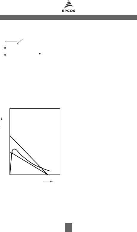
Another quantity affecting the rated current is the ambient temperature at which the PTC thermistor is operated. Figure 4 illustrates this relationship. An increase in ambient temperature means that the PTC thermistor reaches the temperature causing it to trip with much less power consumption. A cooler environment has the opposite effect, i.e. power consumption and rated current rise.
|
|
|
TPT0326-P |
2,0 |
|
|
|
TPT0429-K |
|||||||||
|
|
V1 >V2 |
|
|
IN (TA ) |
|
|
|
|
|
|
|
|
||||
I |
|
IN (25 ˚C) |
|
|
|
|
|
|
|
||||||||
|
|
|
|
|
|
|
|
|
|
|
|||||||
|
|
|
|
|
|
|
|
|
1,6 |
|
|
|
|
|
|
|
|
|
|
|
|
|
|
|
|
|
1,4 |
|
|
|
|
|
|
|
|
|
|
|
|
|
|
|
|
|
|
|
|
|
|
||||
|
|
|
|
|
|
1,2 |
|
|
|
|
|
|
|
||||
|
|
PPTC RPTC |
|
|
TRef1 |
|
|
|
|
||||||||
|
|
|
1,0 |
|
|
|
|
|
|||||||||
|
|
|
|
|
|
|
TRef2 |
|
|
|
|
||||||
|
|
|
|
|
|
0,8 |
|
TRef3 |
|
|
|
|
|||||
|
IN1 |
|
|
|
|
|
|
|
|
|
|
|
|||||
|
|
|
|
|
|
|
|
|
|
|
|
||||||
|
|
|
|
|
|
|
|
|
|
|
|
|
|
|
|
|
|
|
IN2 |
|
|
|
|
0,6 |
|
|
|
|
|
|
|
||||
|
|
|
|
V1 |
|
0,4 |
|
|
|
|
|
|
|
||||
|
|
|
|
V2 |
|
0,2 |
|
|
|
|
|
|
|
||||
|
|
|
|
|
|
|
|
|
|
|
|
|
|||||
|
|
|
|
|
|
0 |
|
|
|
|
|
|
|
||||
|
|
|
|
|
|
20 40 60 80 100 120 ˚C 160 |
|||||||||||
|
|
|
|
|
|
_20 0 |
|||||||||||
|
|
|
|
Vel |
|
|
|
|
|
|
|
|
|
TA |
|||
|
|
|
|
|
|
|
|
|
|
|
|
|
|||||
Figure 3 |
Figure 4 |
|
|
|
|
|
|
|
|||||||||
Influence of the PTC volume V on the rated current at given resistance RPTC
Standardized rated current IN versus ambient temperature TA (measured in still air)
Parameter: TRef 1 <TRef 2 < TRef 3.
33 10/02

Application Notes
1.1.3Switching time versus switching current
The dynamic heating behavior of the PTC thermistor is determined by the specific heat capacity of the titanate material, which is approx. 3 Ws/cm3. At short switching times – less than 5 s with commonly used overcurrent protection devices – heat dissipation through the surface and lead wires is virtually negligible. Almost the entire electrical dissipation is consumed to heat up the ceramic material, to increase the temperature above the reference temperature and thus to produce a stable operating point on the R/T characteristic. When dissipation increases with rising difference between device temperature and ambient, only a small amount of excess energy remains for heating the component and the result is the switching time curves as a function of switching current shown in figure 5.
EPCOS offers a wide selection of PTC thermistors for overcurrent protection covering rated voltages up to 1000 V (with rated current 8 mA) and rated currents up to 2,1 A (rated voltage 12 V). Many years of volume production and positive experience gained with the long-term features of overcurrent protection components in practice have verified the particularly high safety and reliability of these ceramic PTC thermistors.
10 |
3 |
TPT0430-N |
|
||
|
|
|
s |
|
|
|
|
|
|
|
|
|
|
|
tS |
|
|
|
|
102
101
100
10 _1
0 |
4 |
8 |
12 |
A 16 |
 IS
IS
Figure 5
Switching times tS of some PTC thermistors (parameter: different geometries) versus switching current IS (measured at 25 °C in still air)
34 10/02

Application Notes
1.1.4Selection criteria
In circuit design, the following considerations should be borne in mind when selecting a PTC thermistor as overcurrent protector.
Maximum voltage
During normal operation only a small part of the overall voltage is applied to an overcurrent protection PTC thermistor in series with a load. When it responds, i.e. when it goes high-resistance, it has to handle virtually the entire supply voltage. For this reason the thermistor’s maximum operating voltage Vmax should be chosen sufficiently high. Possible supply voltage fluctuations must also be allowed for.
Rated current and switching current
The next thing is to find a PTC thermistor with sufficiently high rated current (that current at which the thermistor will under no circumstances turn off) within the suitable voltage class. So you should consider whether the overall layout of the circuit can handle the increased power for the short time until the PTC thermistor reduces it. Here a worst-case estimate is necessary. Rated and switching currents depend on the ambient temperature. So, as the worst case for the rated current, the maximum permissible ambient temperature for the application should be taken, and for the switching current the lowest possible ambient temperature.
Maximum permissible switching current at Vmax
When considering possible situations in which the PTC thermistor is to give protection, it is necessary to examine whether there will be conditions in which the maximum permissible switching current will be exceeded. This will generally be the case when it is possible for the load to be shortcircuited. In the data sheets a maximum permissible switching current ISmax is stated for the maximum operating voltage Vmax. Overloading the PTC thermistor by too high a switching current must be avoided. If there is indeed such a risk, e.g. through frequent shorting, it can be countered by connecting a resistor in series with the PTC thermistor.
Selection of reference temperature
EPCOS offers PTC thermistors for overcurrent protection with reference temperatures of 80, 120, 130 and 160 °C. The rated current depends in turn on this reference temperature and the disk diameter of the thermistor. In trying to find an attractively costed solution, one could decide on a component with high reference temperature and a small disk diameter. In this case it is necessary to check whether the high surface temperature of the thermistor in the circuit could lead to undesired side-effects. The circuit board material, the configuration of the surrounding components and the spacing from any enclosure as well as any sealing compounds must all receive due attention.
Environmental effects
If any washing solutions other than those suggested in this data book are used (e.g. isopropyl alcohol), if there is any contact with chemicals or use of potting or sealing compounds, all due care should be taken. The reduction of the titanate ceramic that can be caused by chemical effects on the surface of the thermistor and the resulting formation of low-resistance conducting paths or the altered thermal relations in the sealant can lead to local overheating of the PTC thermistor and thus to failures.
35 10/02

Application Notes
1.1.5Circuit configuration
PTC thermistors can be used for versatile protection applications. The circuit diagram below (figure 6) shows the simplest circuit configuration for protecting a transformer.
|
|
|
Figure 6 |
|
|
|
Simplest circuit for |
|
|
|
protecting a transformer |
|
|
|
(primary side) |
12 V |
230 V |
||
|
|
|
|
PTC thermistors are also employed for input protection of measuring instrumentation up to 1000 V, for household applicances (in particular small equipment) and for vehicle motor and air fan protection.
1.2PTC thermistors for telecommunication applications
A special case of overcurrent protection are PTC thermistors for telecommunication applications.
Overvoltage and current in telephone lines can result from surges due to direct lightning strikes, induction between power lines and phone lines as well as direct contact between power lines and phone lines.
Many international specifications and recommendations (IEC, ITU-T) now stipulate full functionality of equipment after testing for a variety of energy levels whilst safe failure is still permitted for higher levels. The solution here is to use resettable devices such as PTC thermistors, which resume their initial resistance once the disturbance has subsided.
The selection criteria for PTC thermistors for telecommunication applications are the same as applied to standard overcurrent protection PTC thermistors. In addition the following should be considered.
1.2.1Rated current and temperature
The PTC thermistor is primarily used to protect the switching equipment against fault current through direct contact with a power line (power contact) or an induced surge of short duration and low voltage from a neighboring line (power induction). For obvious reasons, the rated current of the PTC thermistor should be kept as low as possible so that the protection responds quickly to overcurrents.
The rated current should typically be slightly higher than the operating current of the system to be protected at the normal operating temperature. Here the dependence of the rated current on the temperature of the ambient must be considered. You can find this dependence in the data sheets.
36 10/02

Application Notes
1.2.2Duration of disturbance – voltage classes
An aspect that is too often neglected is the duration of the power contact. Such disturbances can go undetected for many hours, meaning that the PTC thermistor could be held in the high resistance condition exposed to the line voltage for an indefinite period. EPCOS PTC thermistors for telecommunication applications have a maximum switching voltage of at least 265 VAC and can withstand this condition indefinitely.
1.2.3Imbalance on the line – resistance of PTC thermistor
For most telecom applications the balance between the tip and ring (often referred to as longitudinal balance) is essential. A figure must be assigned to the balance between the line resistances that must apply initially and, after a short cooling period, after operation. Typically 1 ohm is demanded on delivery, which should also apply throughout the service life of a system. EPCOS therefore offers matched or binned PTC thermistors for telecommunication applications where the resistance within one pack unit is selected so that the maximum difference is defined.
As opposed to PTC thermistors made of plastic materials, ceramic PTC thermistors always return to their initial resistance value, even after frequent heating/cooling cycles.
1.3PTC thermistors for picture tube degaussing
PTC thermistors degauss the shadow mask of color picture tubes by reducing the alternating current flowing through the degaussing coil within a short period of time. A large difference between inrush current and residual current is crucial for good degaussing. EPCOS provides leaded and housed PTC thermistors for degaussing purposes. For the housed types, mono, dual and double mono versions are available. In a dual PTC, a PTC connected to the power supply supports heating of another PTC that is connected to the coil (see figure 8). As compared to a mono PTC, this configuration permits the residual current to be further reduced.
 Coil PTC
VN |
Degaussing |
coil |
|
Case |
|
B |
Coil PTC |
C |
|
||
V |
Heater PTC |
Degaussing |
220NV~ |
|
coil |
A
TPT0549-6-E
Figure 7
Degaussing with a mono PTC (leaded or housed)
A PTC thermistor connected in series with the coil degausses the shadow mask of a picture tube. The high inrush current is reduced to a low residual value.
Figure 8
Degaussing with two thermally coupled PTC thermistors
Degaussing with a dual PTC thermistor permits a further reduction of the residual current through the degaussing coil. This is achieved by additionally heating the coil PTC thermistor by means of a second PTC.
37 10/02

Application Notes
There is an unmistakable trend in TV sets and computer monitors towards flat screens. The radius of curvature of these cathode ray tubes has been increased to the extent that viewers now gaze at a virtually flat picture tube. Whereas degaussing is straightforward in conventional CRTs, the tubes of flat screens require a slowly decaying, alternating magnetic field as well as precise coil positioning (directly above the shadow mask). Double mono PTC degaussing thermistors are designed to degauss flat screens in TV sets and monitors (see figure 9). This solution reduces both production costs and standby power consumption.
|
Case |
|
|
|
Coil PTC1 |
C |
|
|
B |
|
|
V |
|
A |
Degaussing |
|
|
||
220NV~ |
Coil PTC2 |
|
coil |
|
|
Figure 9
Degaussing with a double mono PTC thermistors achieves a better decay and reduces standby power consumption.
TPT0792-W-E
1.4PTC thermistors for time delay and switching applications
These PTC thermistors are used when a load in series with the thermistor has to be switched off after a time delay and when switching occurs frequently.
Figures 10a/b show a typical configuration of a PTC thermistor in series with a load and the delayed drop of the load current. The switching function of the PTC thermistor consists in limiting the current flowing through the load at high operating voltages after the thermistor has heated up. Differences in current of a factor of 1000 are the rule here. The switching time tS can be approximated as follows:
tS = |
Cth V (TRef – TA ) |
|
---------------------------------------------------P |
||
|
||
TRef |
Reference temperature of PTC thermistor |
|
TA |
Ambient temperature |
|
Cth |
Heat capacity of PTC thermistor |
|
V |
PTC thermistor volume |
|
P |
Switch-on power of PTC thermistor |
This shows that the switching time can be influenced by the size of the PTC thermistor, its reference temperature and the power supplied. Manufacturing techniques allow a variation of the switching time in a wide range. Switching times are lengthened by increasing the volume or the reference temperature; high power consumption by the PTC thermistor, on the other hand, results in short switching times. The graph in figure 10c shows the switch-off behavior for different levels of current consumption.
38 10/02

Application Notes
a)R T
|
|
|
|
|
|
|
|
IL |
|
|
|
|
|
|
|
|
|
|
|
||
V |
L |
|
|
|||||||
|
|
|
|
|
|
|
|
|
|
|
|
|
|
|
|
|
|
|
|
|
|
|
|
|
|
|
TPT0329-E |
|
||||
b) |
|
|
|
|
|
|
TPT0330-H |
c) |
||
IL |
|
|
|
|
|
|
IPTC |
|||
V |
t |
 t
t
Figure 10
Typical configuration of a PTC thermistor for time delay (a) Typical delay of the load current IL (b)
Typical switch-off behavior of a PTC thermistor (c)
TPT0331-Q
 t
t
39 10/02

Application Notes
A typical application for switching PTCs is the preheating of electrodes in energy-saving lamps or fluorescent lamps. Here the PTC is connected in series with the two electrodes of the lamp (see figure 11). When the rectified line is applied to the circuit the PTC is cold and low resistance. The lamp voltage is below the ignition voltage and the flowing current heats the electrodes and the PTC. After a certain period the PTC will switch, the voltage across the lamp will exceed the ignition voltage and the lamp will start to burn. Preheating of the electrodes lengthens the life of the lamp significantly. A full range of standard devices is available and custom engineered samples can be rapidly created for special lamp designs.
Switching PTCs can also be used as a power resistor for loading capacitors, for example in power supplies or in control units of production equipment. Depending on the applied voltage and the capaciance of the capacitor, one or more PTCs in parallel will be necessary to load the capacitor. In contrast to fixed resistors, the PTC also offers protection against a possible shortcircuit in the capacitor. EPCOS PTCs in housings are recommended in case of a large number of switching cycles.
|
Electrode |
|
VAC |
PTC |
|
Lamp |
||
30 to 70 kHz |
||
Optional: |
||
|
||
|
Varistor |
|
|
Electrode |
|
|
TPT0678-Q |
1.5PTC thermistors for motor starting
Figure 11
Principle circuit diagram for the preheating of electrodes in energy-saving lamps or fluorescent lamps
Single-phase induction motors (e.g. in compressors for refrigerators and air conditioners) can effectively be started when an auxiliary coil is used in the starting phase. The auxiliary coil is cut off from the circuit after the starting phase. For this purpose PTC thermistors are employed.
When high voltage is applied to the PTC thermistor, the high current causes the PTC to heat up and eventually the resistance to increase. A high current flows initially (starting phase) and then decreases in relation to the increase in resistance. After the starting phase (at times >> tS), a low residual current flows through the auxiliary coil.
|
|
|
|
|
|
|
Figure 12 |
|
|
|
|
|
|
|
Simple starter circuit for single-phase AC motors |
|
|
|
|
|
|
|
|
|
|
|
|
|
|
|
|
V |
|
|
|
|
|
The PTC thermistor is used for delaying |
|
|
|
|
|
|
|||
|
|
|
|
|
the switch-off of the starter auxiliary winding |
||
|
|
|
|
|
|
PTC |
|
|
|
|
|
|
|
||
|
|
|
|
|
|
(after the motor has accelerated) to protect the |
|
|
|
|
|
|
|
|
|
|
|
|
|
|
|
|
winding from damage |
|
|
|
|
|
|
|
|
|
|
|
|
|
|
||
|
|
TPT0793-5 |
|
||||
40 10/02