

MOTOROLA
SEMICONDUCTOR TECHNICAL DATA
Order this document by MRF464/D
The RF Line
NPN Silicon
RF Power Transistor
. . . designed primarily for applications as a high±power linear amplifier from 2.0 to 30 MHz, in single sideband mobile, marine and base station equipment.
• Specified 28 Volt, 30 MHz Characteristics Ð Output Power = 80 W (PEP)
Minimum Gain = 15 dB Efficiency = 40%
Intermodulation Distortion = ±32 dB (Max)
MATCHING PROCEDURE
MRF464
80 W (PEP), 30 MHz
RF POWER
TRANSISTOR
NPN SILICON
In the push±pull circuit configuration it is preferred that the transistors are used as matched pairs to obtain optimum performance.
The matching procedure used by Motorola consists of measuring hFE at the data sheet conditions and color coding the device to predetermined hFE ranges within the normal hFE limits. A color dot is added to the marking on top of the cap. Any two devices with the same color dot can be paired together to form a matched set of units.
MAXIMUM RATINGS |
|
|
|
|
|
|
|
|
|
|
|
|
|
|
|
|
|
|
|
|
|
|
|
|
|
|
|
|
|
|
|
|
|
||
|
|
|
|
|
|
|
|
|
|
|
|
|
|
|
|
|
|
Rating |
|
Symbol |
Value |
|
Unit |
|
|
|
|
|
|
|
|
|
|
|
|
|
|
|
|
|
|
|
|
|
|
|
|
|
|
|
|
|
|
Collector±Emitter Voltage |
|
VCEO |
35 |
|
Vdc |
|
|
|
|
|
|
|
|
|
|
|
|
|
|
|
|
|
|
|
|
|
|
|
|
|
|||||
Collector±Base Voltage |
|
VCBO |
65 |
|
Vdc |
|
|
|
|
|
|
|
|
|
|
|
|
Emitter±Base Voltage |
|
VEBO |
4.0 |
|
Vdc |
|
|
|
|
|
|
|
|
|
|
|
|
Collector Current Ð Continuous |
|
IC |
10 |
|
Adc |
|
|
|
|
|
|
|
|
|
|
|
|
Total Device Dissipation @ TC = 25°C |
|
PD |
250 |
|
Watts |
|
|
|
|
|
|
|
|
|
|
|
|
Derate above 25°C |
|
|
1.4 |
|
W/°C |
|
|
CASE 211±11, STYLE 1 |
|||||||||
|
|
|
|
|
|
|
|
|
|||||||||
Storage Temperature Range |
|
Tstg |
± 65 to +150 |
|
°C |
|
|
|
|
|
|
|
|
|
|
|
|
THERMAL CHARACTERISTICS |
|
|
|
|
|
|
|
|
|
|
|
|
|
|
|
|
|
|
|
|
|
|
|
|
|
|
|
|
|
|
|
|
|
||
Characteristic |
|
|
|
|
Symbol |
|
|
Max |
|
Unit |
|||||||
|
|
|
|
|
|
|
|
|
|
|
|
|
|
|
|
|
|
Thermal Resistance, Junction to Case |
|
|
|
|
|
RθJC |
|
|
0.7 |
|
|
|
°C/W |
||||
Stud Torque (1) |
|
|
|
|
Ð |
|
|
|
8.5 |
|
|
|
In. Lb. |
||||
ELECTRICAL CHARACTERISTICS (TC = 25°C unless otherwise noted.) |
|
|
|
|
|
|
|
|
|
|
|
|
|
||||
|
|
|
|
|
|
|
|
|
|
|
|
|
|
|
|
||
Characteristic |
|
|
|
|
Symbol |
Min |
|
|
|
Max |
|
Unit |
|||||
|
|
|
|
|
|
|
|
|
|
|
|
|
|
|
|
|
|
OFF CHARACTERISTICS |
|
|
|
|
|
|
|
|
|
|
|
|
|
|
|
|
|
|
|
|
|
|
|
|
|
|
|
|
|
|
|
|
|
||
Collector±Emitter Breakdown Voltage |
|
|
|
|
V(BR)CEO |
35 |
|
|
|
Ð |
|
|
Vdc |
||||
(IC = 100 mAdc, IB = 0) |
|
|
|
|
|
|
|
|
|
|
|
|
|
|
|
|
|
Collector±Emitter Breakdown Voltage |
|
|
|
|
V(BR)CES |
65 |
|
|
|
Ð |
|
|
Vdc |
||||
(IC = 100 mAdc, VBE = 0) |
|
|
|
|
|
|
|
|
|
|
|
|
|
|
|
|
|
Emitter±Base Breakdown Voltage |
|
|
|
|
V(BR)EBO |
4.0 |
|
|
Ð |
|
|
Vdc |
|||||
(IE = 1.0 mAdc, IC = 0) |
|
|
|
|
|
|
|
|
|
|
|
|
|
|
|
|
|
Collector Cutoff Current |
|
|
|
|
|
ICES |
Ð |
|
|
|
10 |
|
mAdc |
||||
(VCE = 28 Vdc, VBE = 0, TC = +55°C) |
|
|
|
|
|
|
|
|
|
|
|
|
|
|
|
|
|
ON CHARACTERISTICS |
|
|
|
|
|
|
|
|
|
|
|
|
|
|
|
|
|
|
|
|
|
|
|
|
|
|
|
|
|
|
|
|
|
||
DC Current Gain |
|
|
|
|
|
hFE |
10 |
|
|
|
Ð |
|
Ð |
||||
(IC = 0.5 Adc, VCE = 5.0 Vdc) |
|
|
|
|
|
|
|
|
|
|
|
|
|
|
|
|
|
NOTE: |
|
|
|
|
|
|
|
|
|
|
|
|
|
|
|
(continued) |
|
1. Case 145A±10 Ð For Repeated Assembly Use 1 1 In. Lb. |
|
|
|
|
|
|
|
|
|
|
|
|
|
||||
Motorola, Inc. 1994

ELECTRICAL CHARACTERISTICS Ð continued (TC = 25°C unless otherwise noted.)
Characteristic |
Symbol |
Min |
Max |
Unit |
|
|
|
|
|
DYNAMIC CHARACTERISTICS |
|
|
|
|
|
|
|
|
|
Output Capacitance |
Cob |
Ð |
200 |
pF |
(VCB = 28 Vdc, IE = 0, f = 1.0 MHz) |
|
|
|
|
FUNCTIONAL TESTS |
|
|
|
|
|
|
|
|
|
Common±Emitter Amplifier Power Gain (Figure 1) |
GPE |
15 |
Ð |
dB |
(Pout = 80 W (PEP), IC = 3.6 Adc (Max), VCC = 28 Vdc, |
|
|
|
|
f1 = 30 MHz, f2 = 30.001 MHz) |
|
|
|
|
Intermodulation Distortion Ratio (Figure 1) (2) |
IMD |
Ð |
± 32 |
dB |
(Pout = 80 W (PEP), IC = 3.6 Adc (Max), VCC = 28 Vdc, |
|
|
|
|
f1 = 30 MHz, f2 = 30.001 MHz) |
|
|
|
|
Collector Efficiency |
h |
40 |
Ð |
% |
(Pout = 80 W (PEP), IC = 3.6 Adc (Max), VCC = 28 Vdc, |
|
|
|
|
f1 = 30 MHz, f2 = 30.001 MHz) |
|
|
|
|
NOTE: |
|
|
|
|
2. To Mil±Std±1311 Version A, Test Method 2204B, Two Tone, Reference each Tone.
VBB
|
|
|
|
RF BEADS |
|
|
|
|
|
|
|
|
|
|
+ |
500 mF |
1N248B |
0.01 mF |
|
2000 pF |
0.01 mF |
25 mF |
28 Vdc |
|
BUTTON |
||||||
|
|
|
|
|
|
|
|
|
|
10 mH |
RFC |
|
|
|
± |
|
|
RFC |
|
|
|
||
|
|
|
|
|
RL = 50 W |
|
|
|
|
|
|
|
|
|
|
|
|
|
0.1 mF |
|
|
|
|
|
|
|
DUT |
|
|
|
|
|
|
ARCO 466 |
|
|
|
|
|
|
|
(80± 480 pF) |
|
|
|
T2 |
|
|
|
|
|
|
|
|
|
|
ARCO 469 |
T1 |
10 |
|
|
(1:9) |
|
|
C.T. |
|
|
|
|
||
|
(170± 780 pF) |
1/2 W |
C1 |
|
|
|
|
|
|
|
C2 |
|
|
|
|
RFC Ð 20 Turns @12 AWG Enameled Wire Close Wound in 2 Layers, 1/4 ″ I.D. T1 Ð 20 Turns #24 AWG Wire W ound on Micro±Metals T37±7 Toroid Core
T1 Ð Center Tapped.
T2 Ð 1:9 XFMR; 6 Turns of 2 Twisted Pairs of #28 AWG Enameled Wire. T2 Ð (8 Crests Per Inch) Bifilar Wound on Each of 2 Separate Balun Cores. T2 Ð (Stackpole #57±1503, No. 14 Material) Interconnected as shown
T2 Ð RF Beads Ð Ferroxcube #56±590±65/3B
VBB adjusted for ICQ Ð 40 mAdc (I CQ = Quiescent VBB adjusted for ICQ Ð 40 mAdc Collector Current)
C1 Ð 170± 180 pF ARCO 469 or Equivalent
C2 Ð 330 pF
Figure 1. 30 MHz Test Circuit
MRF464 |
MOTOROLA RF DEVICE DATA |
2 |
|
|
120 |
|
|
|
|
|
|
|
|
|
|
|
|
|
|
(WATTS) |
100 |
|
VCC = 28 Vdc |
|
|
|
|
|
|
|
|
|
|
||
|
IGQ = 40 mA |
|
|
|
|
|
|
|
|
|
|
||||
|
|
f = 30 MHz |
|
|
|
|
|
|
|
|
|
|
|||
80 |
|
|
|
|
|
|
|
|
|
|
|
|
|
|
|
POWER |
|
|
|
|
|
|
|
|
|
|
|
|
|
|
|
60 |
|
|
|
|
|
|
|
|
|
|
|
|
|
|
|
, OUTPUT |
|
|
|
|
|
|
|
|
|
|
|
|
|
|
|
40 |
|
|
|
|
|
|
|
|
|
|
|
|
|
|
|
|
|
|
|
|
|
|
|
|
|
|
|
|
|
|
|
out |
|
|
|
|
|
|
|
|
|
|
|
|
|
|
|
P |
20 |
|
|
|
|
|
|
|
|
|
|
|
|
|
|
|
|
|
|
|
|
|
|
|
|
|
|
|
|
|
|
|
0 |
0.2 |
0.4 |
0.6 |
0.8 |
1 |
1.2 |
1.4 |
1.6 |
1.8 |
2 |
2.2 |
2.4 |
2.6 |
2.8 |
|
0 |
||||||||||||||
Pin, INPUT POWER (WATTS)
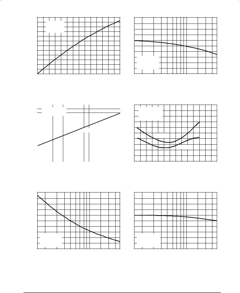
Figure 2. Output Power versus Input Power
|
140 |
|
|
|
|
|
|
|
|
|
|
|
|
|
|
|
|
PEP) |
|
ICQ |
= 40 mA |
|
|
|
|
|
|
|
|
|
|
|
|
|
|
120 |
|
|
|
|
|
|
|
|
|
|
|
|
|
|
|||
|
f = |
30, 30.001 |
MHz |
|
|
|
|
|
|
|
|
|
|
|
|||
(WATTS |
|
|
|
|
|
|
|
|
|
|
|
|
|||||
100 |
|
|
|
|
|
|
|
|
|
|
|
|
|
|
|
|
|
|
|
|
|
|
|
|
|
|
|
|
|
|
|
|
|
||
|
|
|
|
|
|
|
|
|
|
|
|
|
|
|
|
|
|
POWER |
80 |
|
|
|
|
|
|
|
|
|
|
|
|
|
|
|
|
|
|
|
|
|
|
|
|
|
|
|
|
|
|
|
|
||
|
|
|
|
|
|
|
|
|
IMD = ±30 |
dB |
|
|
|
|
|
||
60 |
|
|
|
|
|
|
|
|
|
|
|
|
|
|
|||
|
|
|
|
|
|
|
|
|
|
|
|
|
|
|
|
||
OUTPUT, |
40 |
|
|
|
|
|
|
|
|
|
|
|
|
|
|
|
|
|
|
|
|
|
|
|
|
|
|
|
|
|
|
|
|
||
|
|
|
|
|
|
|
|
|
|
|
|
|
|
|
|
||
out |
|
|
|
|
|
|
|
|
|
|
|
|
|
|
|
|
|
20 |
|
|
|
|
|
|
|
|
|
|
|
|
|
|
|
|
|
|
|
|
|
|
|
|
|
|
|
|
|
|
|
|
|
||
|
|
|
|
|
|
|
|
|
|
|
|
|
|
|
|
||
P |
|
|
|
|
|
|
|
|
|
|
|
|
|
|
|
|
|
|
0 |
|
|
|
|
|
|
|
|
|
|
|
|
|
|
|
|
|
|
|
|
|
|
|
|
|
|
|
|
|
|
|
|
|
|
|
|
20 |
|
24 |
28 |
|
|
32 |
|||||||||
|
16 |
|
|
|
|||||||||||||
VCC, SUPPLY VOLTAGE (VOLTS)
Figure 4. Output Power versus Supply Voltage
|
50 |
|
|
|
|
|
|
|
|
(dB) |
40 |
|
|
|
|
|
|
|
|
|
|
|
|
|
|
|
|
|
|
POWER GAIN |
30 |
|
|
|
|
|
|
|
|
20 |
|
|
|
|
|
|
|
|
|
, |
|
|
|
|
|
|
|
|
|
PE |
|
VCC = 28 Vdc |
|
|
|
|
|
|
|
G |
|
|
|
|
|
|
|
||
|
10 |
ICQ = 40 mA |
|
|
|
|
|
|
|
|
|
Pout = 80 W PEP |
|
|
|
|
|
|
|
|
0 |
2 |
3 |
5 |
7 |
10 |
15 |
20 |
30 |
|
1.5 |
||||||||
f, FREQUENCY (MHz)
Figure 3. Power Gain versus Frequency
(dB) |
±10 |
|
|
|
|
|
|
|
|
VCC = 28 Vdc |
|
|
|
|
|
|
|
DISTORTION |
± 20 |
ICQ = 40 mA |
|
|
|
|
|
|
f = 30, 30.001 MHz |
|
|
|
|
|
|||
± 30 |
|
|
|
|
|
|
|
|
IMD, INTERMODULATION |
|
|
|
|
|
|
|
|
± 40 |
3RD ORDER |
|
|
|
|
|
||
|
|
|
|
|
|
|
||
± 50 |
|
|
|
5TH ORDER |
|
|
||
|
|
|
|
|
|
|
||
± 60 |
|
|
|
|
|
|
|
|
|
|
|
|
|
|
|
|
|
|
0 |
20 |
40 |
60 |
80 |
100 |
120 |
140 |
Pout, OUTPUT POWER (WATTS PEP)
Figure 5. Intermodulation Distortion versus Output Power
|
2500 |
|
|
|
|
|
|
|
|
OUTPUT |
2000 |
|
|
|
|
|
|
|
|
|
|
|
|
|
|
|
|
|
|
,PARALLEL EQUIVALENT |
1500 |
|
|
|
|
|
|
|
|
1000 |
|
|
|
|
|
|
|
|
|
CAPACITANCE(pF) |
VCC = 28 Vdc |
|
|
|
|
|
|
||
out |
500 |
ICQ = 40 mA |
|
|
|
|
|
|
|
|
|
|
|
|
|
|
|||
C |
|
Pout = 80 W PEP |
|
|
|
|
|
|
|
|
|
|
|
|
|
|
|
||
|
1.5 |
2 |
3 |
5 |
7 |
10 |
15 |
20 |
30 |
|
|
10 |
|
|
|
|
|
|
|
|
, PARALLEL EQUIVALENT OUTPUT |
RESISTANCE (OHMS) |
8 |
|
|
|
|
|
|
|
|
6 |
|
|
|
|
|
|
|
|
||
4 |
|
|
|
|
|
|
|
|
||
2 |
VCC = 28 Vdc |
|
|
|
|
|
|
|||
out |
|
ICQ = 40 mA |
|
|
|
|
|
|
||
|
|
|
|
|
|
|
|
|||
R |
|
|
Pout = 80 W (PEP) |
|
|
|
|
|
|
|
|
|
0 |
|
|
|
|
|
|
||
|
|
1.5 |
2 |
3 |
5 |
7 |
10 |
15 |
20 |
30 |
f, FREQUENCY (MHz) |
f, FREQUENCY (MHz) |
Figure 6. Output Capacitance versus Frequency |
Figure 7. Output Resistance versus Frequency |
MOTOROLA RF DEVICE DATA |
MRF464 |
|
3 |

|
10 |
|
|
|
|
|
|
|
|
(AMPS) |
8 |
|
|
|
|
|
|
|
|
|
|
|
|
|
|
|
|
|
|
CURRENT |
6 |
|
|
|
|
|
|
|
|
|
|
|
|
|
|
|
|
|
|
, COLLECTOR |
4 |
|
|
|
|
|
|
|
|
2 |
|
|
|
|
|
|
|
|
|
C |
|
|
|
|
|
|
|
|
|
I |
|
|
|
|
|
|
|
|
|
|
0 |
5 |
10 |
15 |
20 |
25 |
30 |
35 |
40 |
|
0 |
VCC, COLLECTOR±EMITTER VOLTAGE (VOLTS)
Figure 8. DC Safe Operating Area
2.0
3.0
4.0
VCC = 28 Vdc
ICQ = 40 mA
Pout = 80 W PEP
FREQUENCY |
Zin |
MHz |
Ohms |
2.09.0 ± j5.40
7.03.3 ± j1.50
15 |
2.8 ± j1.10 |
30 |
1.4 ± j0.30 |
1.0
30
15
7.0
 2.0 f = 2.0 MHz 4.0
6.0
0
1.0
2.0
3.0
4.0
5.0
6.0
7.0
8.0
9.0
10
2.0
12
Figure 9. Series Input Impedance
MRF464 |
MOTOROLA RF DEVICE DATA |
4 |
|

PACKAGE DIMENSIONS
|
A |
|
NOTES: |
|
|
|
|
|
U |
|
|
|
|
|
|
|
|
1. DIMENSIONING AND TOLERANCING PER ANSI |
|||||
|
M |
|
|||||
|
|
Y14.5M, 1982. |
|
|
|
||
|
|
|
2. CONTROLLING DIMENSION: INCH. |
||||
1 |
M |
|
|
INCHES |
MILLIMETERS |
||
Q |
|
|
|||||
4 |
|
DIM |
MIN |
MAX |
MIN |
MAX |
|
|
|
A |
0.960 |
0.990 |
24.39 |
25.14 |
|
|
|
|
|||||
|
R |
B |
B |
0.465 |
0.510 |
11.82 |
12.95 |
|
C |
0.229 |
0.275 |
5.82 |
6.98 |
||
|
|
|
D |
0.216 |
0.235 |
5.49 |
5.96 |
|
|
|
E |
0.084 |
0.110 |
2.14 |
2.79 |
2 |
3 |
|
H |
0.144 |
0.178 |
3.66 |
4.52 |
|
J |
0.003 |
0.007 |
0.08 |
0.17 |
||
|
D |
|
K |
0.435 |
±±± |
11.05 |
±±± |
|
|
M |
45 |
NOM |
45 |
NOM |
|
K |
|
|
|||||
|
|
Q |
0.115 |
0.130 |
2.93 |
3.30 |
|
|
|
|
R |
0.246 |
0.255 |
6.25 |
6.47 |
J |
|
|
U |
0.720 |
0.730 |
18.29 |
18.54 |
|
|
|
|
|
|
|
|
|
C |
|
STYLE 1: |
|
H |
|
PIN 1. |
EMITTER |
|
E |
SEATING |
2. |
BASE |
|
|
3. |
EMITTER |
||
|
|
PLANE |
||
|
|
4. |
COLLECTOR |
|
|
|
|
CASE 211±11
ISSUE N
MOTOROLA RF DEVICE DATA |
MRF464 |
|
5 |

Motorola reserves the right to make changes without further notice to any products herein. Motorola makes no warranty, representation or guarantee regarding the suitability of its products for any particular purpose, nor does Motorola assume any liability arising out of the application or use of any product or circuit, and specifically disclaims any and all liability, including without limitation consequential or incidental damages. ªTypicalº parameters can and do vary in different applications. All operating parameters, including ªTypicalsº must be validated for each customer application by customer's technical experts. Motorola does not convey any license under its patent rights nor the rights of others. Motorola products are not designed, intended, or authorized for use as components in systems intended for surgical implant into the body, or other applications intended to support or sustain life, or for any other application in which the failure of the Motorola product could create a situation where personal injury or death may occur. Should Buyer purchase or use Motorola products for any such unintended or unauthorized application, Buyer shall indemnify and hold Motorola and its officers, employees, subsidiaries, affiliates, and distributors harmless against all claims, costs, damages, and expenses, and reasonable attorney fees arising out of, directly or indirectly, any claim of personal injury or death associated with such unintended or unauthorized use, even if such claim alleges that Motorola was negligent regarding the design or manufacture of the part. Motorola and  are registered trademarks of Motorola, Inc. Motorola, Inc. is an Equal Opportunity/Affirmative Action Employer.
Literature Distribution Centers:
USA: Motorola Literature Distribution; P.O. Box 20912; Phoenix, Arizona 85036.
EUROPE: Motorola Ltd.; European Literature Centre; 88 Tanners Drive, Blakelands, Milton Keynes, MK14 5BP, England. JAPAN: Nippon Motorola Ltd.; 4-32-1, Nishi-Gotanda, Shinagawa-ku, Tokyo 141, Japan.
ASIA PACIFIC: Motorola Semiconductors H.K. Ltd.; Silicon Harbour Center, No. 2 Dai King Street, Tai Po Industrial Estate, Tai Po, N.T., Hong Kong.
◊ |
MRF464/D |
|
*MRF464/D* |