

S E M I C O N D U C T O R
April 1995
RHRP3070, RHRP3080, RHRP3090, RHRP30100
30A, 700V - 1000V Hyperfast Diodes
Features |
|
Package |
|||||||||
• Hyperfast with Soft Recovery . . . . . . . . . . . . . . . |
. <65ns |
|
|
|
|
JEDEC TO-220AC |
|||||
• |
Operating Temperature . . . . . . . . . . . . . . . . . . . . |
+175oC |
|
|
|
|
|
|
|
|
ANODE |
|
|
|
|
|
|
|
|
|
|
|
|
• Reverse Voltage Up To . . . . . . . . . . . . . . . . . . . . |
. 1000V |
|
|
|
|
|
|
|
|
CATHODE |
|
• |
Avalanche Energy Rated |
|
CATHODE |
|
|
||||||
• |
Planar Construction |
|
(FLANGE) |
|
|
|
|||||
|
|
|
|
|
|
|
|
|
|
||
|
|
|
|
|
|
|
|
|
|
|
|
Applications
•Switching Power Supplies
•Power Switching Circuits
• General Purpose |
Symbol |
|
|
Description |
K |
|
|
RHRP3070, RHRP3080, RHRP3090 and RHRP30100 |
|
(TA49064) are hyperfast diodes with soft recovery character- |
|
istics (tRR < 65ns). They have half the recovery time of |
|
ultrafast diodes and are silicon nitride passivated ion- |
A |
implanted epitaxial planar construction. |
|
These devices are intended for use as freewheeling/clamping diodes and rectifiers in a variety of switching power supplies and other power switching applications. Their low stored charge and hyperfast soft recovery minimize ringing and electrical noise in many power switching circuits reducing power loss in the switching transistors.
|
PACKAGING AVAILABILITY |
|
|
|
|
|
|
|
|
||||
|
|
|
|
|
|
|
|
|
|
|
|
|
|
|
PART NUMBER |
|
PACKAGE |
BRAND |
|
|
|
|
|
|
|
|
|
|
|
|
|
|
|
|
|
|
|
|
|
|
|
|
RHRP3070 |
|
TO-220AC |
RHRP3070 |
|
|
|
|
|
|
|
|
|
|
|
|
|
|
|
|
|
|
|
|
|
|
|
|
RHRP3080 |
|
TO-220AC |
RHRP3080 |
|
|
|
|
|
|
|
|
|
|
|
|
|
|
|
|
|
|
|
|
|
|
|
|
RHRP3090 |
|
TO-220AC |
RHRP3090 |
|
|
|
|
|
|
|
|
|
|
|
|
|
|
|
|
|
|
|
|
|
|
|
|
RHRP30100 |
|
TO-220AC |
RHR30100 |
|
|
|
|
|
|
|
|
|
|
|
|
|
|
|
|
|
|
|
|
|
|
|
|
NOTE: When ordering, use the entire part number. |
|
|
|
|
|
|
|
|
||||
|
|
|
|
|
|
|
|||||||
Absolute Maximum Ratings TC = +25oC, Unless Otherwise Specified |
|
|
|
|
|
||||||||
|
|
|
|
|
|
|
|
RHRP3070 |
RHRP3080 |
RHRP3090 |
RHRP30100 |
UNITS |
|
Peak Repetitive Reverse Voltage . . . . . . . . . |
. . . . . . . . . . . . . . . . . . . |
VRRM |
700 |
800 |
900 |
1000 |
V |
||||||
Working Peak Reverse Voltage . . . . . . . . . . |
. . . . . . . . . . . . . . . . . . . |
VRWM |
700 |
800 |
900 |
1000 |
V |
||||||
DC Blocking Voltage . |
. |
. . . . . . . . . . . . . . . . . |
. . . . . . . . . . . . . . . . . . . |
. . |
VR |
700 |
800 |
900 |
1000 |
V |
|||
Average Rectified Forward Current . . . . . . . |
. . . . . . . . . . . . . . . . . . . |
IF(AV) |
30 |
30 |
30 |
30 |
A |
||||||
|
(TC = +95oC) |
|
|
|
|
|
|
|
|
|
|
|
|
Repetitive Peak Surge Current . . . . . . . . . . . |
. . . . . . . . . . . . . . . . . . . |
. IFSM |
70 |
70 |
70 |
70 |
A |
||||||
|
(Square Wave, 20kHz) |
|
|
|
|
|
|
|
|
|
|
||
Nonrepetitive Peak Surge Current . . . . . . . . |
. . . . . . . . . . . . . . . . . . . |
. IFSM |
325 |
325 |
325 |
325 |
A |
||||||
|
(Halfwave, 1 Phase, 60Hz) |
|
|
|
|
|
|
|
|
|
|
||
Maximum Power Dissipation. . . . . . . . . . . . . |
. . . . . . . . . . . . . . . . . . . |
. . |
PD |
125 |
125 |
125 |
125 |
W |
|||||
Avalanche Energy (See Figures 10 and 11) . |
. . . . . . . . . . . . . . . . . . . |
EAVL |
20 |
20 |
20 |
20 |
mj |
||||||
Operating and Storage Temperature . . . . . . |
. . . . . . . . . . . . . . . . T |
, T |
J |
-65 to +175 |
-65 to +175 |
-65 to +175 |
-65 to +175 |
oC |
|||||
|
|
|
|
STG |
|
|
|
|
|
|
|
||
|
|
|
|
|
|
|
|
|
|
|
|
|
|
Copyright © Harris Corporation 1995 |
|
|
|
|
|
|
|
File Number |
3940.1 |
||||
7-82
Specifications RHRP3070, RHRP3080, RHRP3090, RHRP30100
Electrical Specifications TC = +25oC, Unless Otherwise Specified
|
|
|
|
|
|
|
|
|
|
|
RHRP3070 |
RHRP3080 |
RHRP3090 |
RHRP30100 |
|
||||||||
|
|
|
|
|
|
|
|
|
|
|
|
|
|
|
|
|
|
|
|||||
SYMBOL |
|
|
|
|
TEST CONDITION |
MIN |
TYP |
MAX |
MIN |
TYP |
MAX |
MIN |
TYP |
MAX |
MIN |
TYP |
MAX |
UNITS |
|||||
|
|
|
|
|
|
|
|
|
|
|
|
|
|
|
|
|
|
|
|
||||
V |
I |
F |
= 30A, T |
C |
= +25oC |
- |
- |
3.0 |
- |
- |
3.0 |
- |
- |
3.0 |
- |
- |
3.0 |
V |
|||||
|
F |
|
|
|
|
|
|
|
|
|
|
|
|
|
|
|
|
|
|
|
|||
|
|
I |
F |
= 30A, T |
C |
= +150oC |
- |
- |
2.5 |
- |
- |
2.5 |
- |
- |
2.5 |
- |
- |
2.5 |
V |
||||
|
|
|
|
|
|
|
|
|
|
|
|
|
|
|
|
|
|
|
|
|
|||
|
|
|
|
|
|
|
|
|
|
|
|
|
|
|
|
|
|
|
|
|
|||
I |
R |
V |
R |
= 700V, T |
C |
= +25oC |
- |
- |
500 |
- |
- |
- |
- |
- |
- |
- |
- |
- |
μA |
||||
|
|
|
|
|
|
|
|
|
|
|
|
|
|
|
|
|
|
|
|
||||
|
|
|
|
|
|
|
|
|
|
|
|
|
|
|
|
|
|
|
|
|
|||
|
|
V |
R |
= 800V, T |
C |
= +25oC |
- |
- |
- |
- |
- |
500 |
- |
- |
- |
- |
- |
- |
μA |
||||
|
|
|
|
|
|
|
|
|
|
|
|
|
|
|
|
|
|
|
|
|
|||
|
|
|
|
|
|
|
|
|
|
|
|
|
|
|
|
|
|
|
|
|
|||
|
|
V |
R |
= 900V, T |
C |
= +25oC |
|
|
|
|
|
|
- |
- |
500 |
|
|
|
μA |
||||
|
|
|
|
|
|
|
|
|
|
|
|
|
|
|
|
|
|
|
|
|
|||
|
|
|
|
|
|
|
|
|
|
|
|
|
|
|
|
||||||||
|
|
VR = 1000V, TC = +25oC |
- |
- |
- |
- |
- |
- |
- |
- |
- |
- |
- |
500 |
μA |
||||||||
I |
R |
V |
R |
= 700V, T |
C |
= +150oC |
- |
- |
1.0 |
- |
- |
- |
- |
- |
- |
- |
- |
- |
mA |
||||
|
|
|
|
|
|
|
|
|
|
|
|
|
|
|
|
|
|
|
|
|
|||
|
|
V |
R |
= 800V, T |
C |
= +150oC |
- |
- |
- |
- |
- |
1.0 |
- |
- |
- |
- |
- |
- |
mA |
||||
|
|
|
|
|
|
|
|
|
|
|
|
|
|
|
|
|
|
|
|
|
|||
|
|
|
|
|
|
|
|
|
|
|
|
|
|
|
|
|
|
|
|
|
|||
|
|
V |
R |
= 900V, T |
C |
= +150oC |
|
|
|
|
|
|
- |
- |
1.0 |
|
|
|
mA |
||||
|
|
|
|
|
|
|
|
|
|
|
|
|
|
|
|
||||||||
|
|
VR = 1000V, TC = +150oC |
- |
- |
- |
- |
- |
- |
- |
- |
- |
- |
- |
1.0 |
mA |
||||||||
tRR |
IF = 1A, dIF/dt = 100A/μs |
- |
- |
65 |
- |
- |
65 |
- |
- |
65 |
- |
- |
65 |
ns |
|||||||||
|
|
IF = 30A, dIF/dt = 100A/μs |
- |
- |
75 |
- |
- |
75 |
- |
- |
75 |
- |
- |
75 |
ns |
||||||||
tA |
IF = 30A, dIF/dt = 100A/μs |
- |
35 |
- |
- |
35 |
- |
- |
35 |
- |
- |
35 |
- |
ns |
|||||||||
tB |
IF = 30A, dIF/dt = 100A/μs |
- |
33 |
- |
- |
33 |
- |
- |
33 |
- |
- |
33 |
- |
ns |
|||||||||
QRR |
IF = 30A, dIF/dt = 100A/μs |
- |
200 |
- |
- |
200 |
- |
- |
200 |
- |
- |
200 |
- |
nC |
|||||||||
CJ |
VR = 10V, IF = 0A |
- |
100 |
- |
- |
100 |
- |
- |
100 |
- |
- |
100 |
- |
pF |
|||||||||
RθJC |
|
|
|
|
|
|
|
|
|
- |
- |
1.2 |
- |
- |
1.2 |
|
|
1.2 |
- |
- |
1.2 |
oC/W |
|
DEFINITIONS
VF = Instantaneous forward voltage (pw = 300μs, D = 2%). IR = Instantaneous reverse current.
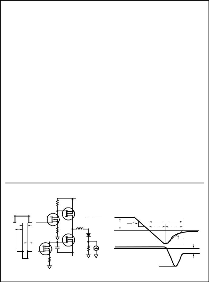
tRR = Reverse recovery time (Figure 2), summation of tA + tB. tA = Time to reach peak reverse current (See Figure 2).
tB = Time from peak IRM to projected zero crossing of IRM based on a straight line from peak IRM through 25% of IRM (See Figure 2). QRR = Reverse recovery charge.
CJ = Junction Capacitance.
RθJC = Thermal resistance junction to case.
EAVL = Controlled avalanche energy. (See Figures 10 and 11). pw = pulse width.
D = duty cycle.
V1 AMPLITUDE CONTROLS IF |
|
|
|
|
V2 AMPLITUDE CONTROLS dIF/dt |
|
|
+V3 |
|
L |
= SELF INDUCTANCE OF |
|
|
|
1 |
R4 + LLOOP |
R1 |
Q2 |
t1 ³ 5tA(MAX) |
|
||||
|
|
|
|
|
|
|
|
|
t2 > tRR |
|
Q1 |
|
|
t3 > 0 |
|
|
|
L1 £ tA(MIN) |
|
|
+V1 |
|
|
|
0 |
|
R4 |
|
10 |
dIF |
|
tRR |
|
LLOOP |
|
IF |
|
|||
|
t2 |
|
dt |
tA |
tB |
||
t1 |
R2 |
|
DUT |
0 |
|
|
|
|
Q4 |
|
|
|
|
||
|
|
|
|
|
|
0.25 IRM |
|
|
|
|
|
|
|
|
|
|
t3 |
|
|
|
|
|
IRM |
0 |
C1 |
R4 |
|
|
|
|
VR |
Q3 |
|
|
|
|
|
||
|
|
|
|
|
|
|
|
-V2 |
R3 |
-V4 |
|
|
|
|
|
VRM
FIGURE 1. tRR TEST CIRCUIT |
FIGURE 2. tRR WAVEFORMS AND DEFINITIONS |
7-83
RHRP3070, RHRP3080, RHRP3090, RHRP30100
Typical Performance Curves
|
300 |
|
|
|
|
|
|
(A) |
100 |
|
|
|
|
|
|
CURRENT |
|
+100oC |
|
|
|
|
|
FORWARD, |
|
|
|
|
|
||
10 |
+175oC |
+25oC |
|
|
|
|
|
|
|
|
|
|
|||
|
|
|
|
|
|
|
|
F |
|
|
|
|
|
|
|
I |
|
|
|
|
|
|
|
|
1 |
|
|
|
|
|
|
|
0 |
1 |
2 |
3 |
4 |
5 |
6 |
|
|
|
VF, FORWARD VOLTAGE (V) |
|
|
||
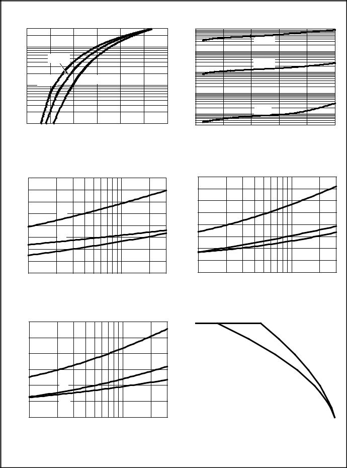
FIGURE 3. TYPICAL FORWARD CURRENT vs FORWARD |
|
||||||
|
|
VOLTAGE DROP |
|
|
|
|
|
|
80 |
|
|
|
|
TC = +25oC |
|
|
|
|
|
|
|
|
|
(ns) |
70 |
|
|
|
|
|
|
60 |
|
|
|
|
|
|
|
TIMES |
|
|
|
|
|
|
|
50 |
|
tRR |
|
|
|
|
|
RECOVERY |
|
|
|
|
|
||
40 |
|
|
|
|
|
|
|
|
|
|
|
|
|
|
|
|
30 |
|
tA |
|
|
|
|
t, |
20 |
|
|
|
|
|
|
|
|
tB |
|
|
|
|
|
|
10 |
|
|
|
|
|
|
|
|
|
|
|
|
|
|
|
0 |
|
|
|
10 |
|
|
|
1 |
|
|
|
|
30 |
|
|
|
|
IF , FORWARD CURRENT (A) |
|
|
||
FIGURE 5. TYPICAL tRR, tA AND tB CURVES vs FORWARD |
|
||||||
|
|
CURRENT AT +25oC |
|
|
|
|
|
|
300 |
|
|
|
|
TC = +175oC |
|
|
|
|
|
|
|
|
|
|
250 |
|
|
|
|
|
|
(ns) |
200 |
|
|
|
|
|
|
TIMES |
|
|
|
|
|
|
|
|
|
tRR |
|
|
|
|
|
|
|
|
|
|
|
|
|
RECOVERYt, |
150 |
|
|
|
|
|
|
100 |
|
tB |
|
|
|
|
|
|
|
|
|
|
|
||
|
50 |
|
tA |
|
|
|
|
0
1 |
10 |
30 |
IF , FORWARD CURRENT (A)
FIGURE 7. TYPICAL tRR, tA AND tB CURVES vs FORWARD CURRENT AT +175oC
|
1200 |
|
|
|
|
|
(μA) |
|
|
|
+175oC |
|
|
100 |
|
|
|
|
|
|
CURRENT |
|
|
|
|
|
|
|
|
|
+100oC |
|
|
|
10 |
|
|
|
|
|
|
|
|
|
|
|
|
|
, REVERSE |
1 |
|
|
|
|
|
|
|
|
|
|
|
|
R |
|
|
|
|
|
|
I |
|
|
|
+25oC |
|
|
|
0.1 |
|
|
|
|
|
|
|
|
|
|
|
|
|
0.03 |
|
|
|
|
|
|
0 |
200 |
400 |
600 |
800 |
1000 |
VR, REVERSE VOLTAGE (V)
FIGURE 4. TYPICAL REVERSE CURRENT vs REVERSE VOLTAGE
TC = +100oC
|
200 |
|
|
|
175 |
|
|
(ns) |
150 |
|
|
|
|
|
|
TIMES |
125 |
tRR |
|
|
|
||
RECOVERY |
100 |
|
|
75 |
tB |
|
|
|
|
||
50 |
|
|
|
t, |
tA |
|
|
|
|
||
|
|
|
|
|
25 |
|
|
|
0 |
10 |
30 |
|
1 |
||
|
|
IF , FORWARD CURRENT (A) |
|
FIGURE 6. TYPICAL tRR, tA AND tB CURVES vs FORWARD CURRENT AT +100oC
(A) |
30 |
|
|
|
|
|
|
|
|
|
|
|
|
|
|
|
|
|
|
|
|
|
|
|
|
||
|
|
|
|
|
|
|
|
|
|
|
|
|
|
CURRENT |
25 |
|
|
|
|
|
|
|
|
|
|
|
|
|
|
|
|
|
|
|
|
|
|
DC |
|
|
|
|
|
|
|
|
|
|
|
|
|
|
|
|
|
FORWARD |
20 |
|
|
|
|
|
|
|
|
|
|
|
|
|
|
|
|
|
|
|
|
|
|
|
|
||
|
|
|
|
|
|
SQ. WAVE |
|
|
|
|
|
||
|
|
|
|
|
|
|
|
|
|
|
|
||
AVERAGE |
15 |
|
|
|
|
|
|
|
|
|
|
|
|
|
|
|
|
|
|
|
|
|
|
|
|
||
|
|
|
|
|
|
|
|
|
|
|
|
||
5 |
|
|
|
|
|
|
|
|
|
|
|
|
|
, |
10 |
|
|
|
|
|
|
|
|
|
|
|
|
|
|
|
|
|
|
|
|
|
|
|
|
|
|
|
|
|
|
|
|
|
|
|
|
|
|
|
|
F(AV) |
0 |
|
|
|
|
|
|
|
|
|
|
|
|
I |
|
|
|
|
|
|
|
|
|
|
|
|
|
|
25 |
50 |
75 |
100 |
125 |
150 |
175 |
||||||
TC , CASE TEMPERATURE (oC)
FIGURE 8. CURRENT DERATING CURVE FOR ALL TYPES
7-84
RHRP3070, RHRP3080, RHRP3090, RHRP30100 |
|
|
||||||
Typical Performance Curves (Continued) |
|
|
|
|
|
|||
|
250 |
|
|
|
|
|
|
|
(pF) |
200 |
|
|
|
|
|
|
|
CAPACITANCE |
|
|
|
|
|
|
|
|
150 |
|
|
|
|
|
|
|
|
|
|
|
|
|
|
|
|
|
, JUNCTION |
100 |
|
|
|
|
|
|
|
50 |
|
|
|
|
|
|
|
|
J |
|
|
|
|
|
|
|
|
C |
|
|
|
|
|
|
|
|
|
0 |
|
|
|
|
|
|
|
|
0 |
|
50 |
100 |
150 |
200 |
|
|
|
|
|
VR , REVERSE VOLTAGE (V) |
|
|
|
||
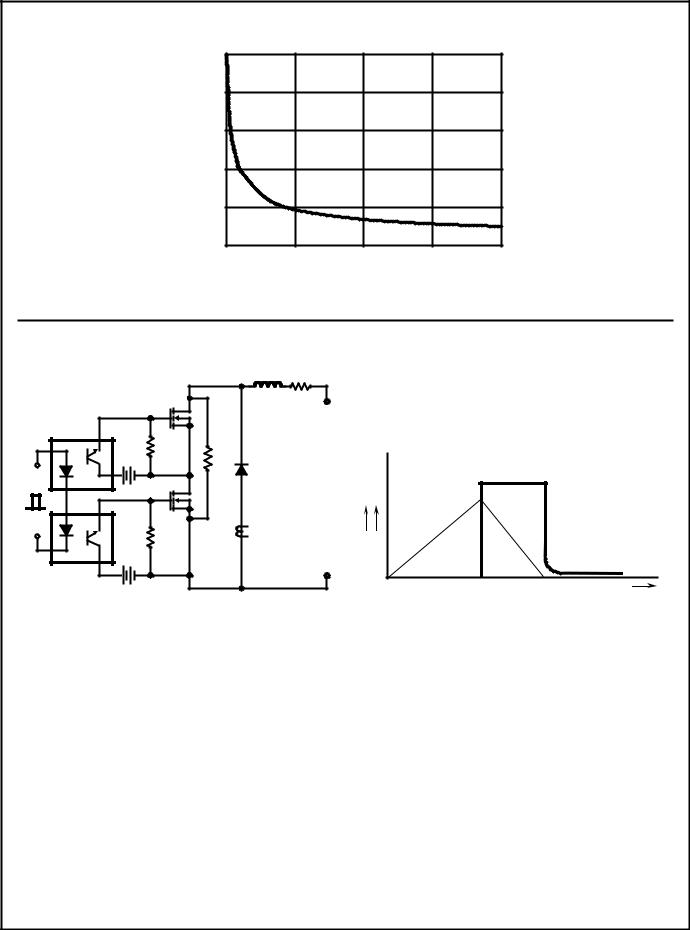
FIGURE 9. TYPICAL JUNCTION CAPACITANCE vs REVERSE VOLTAGE |
|
|
||||||
IMAX = 1A |
|
|
|
|
|
|
|
|
L = 40mH |
|
|
|
|
|
|
|
|
R < 0.1Ω |
|
|
|
|
|
|
|
|
EAVL = 1/2LI2 [VAVL/(VAVL - VDD)] |
|
|
|
|
|
|
|
|
Q1 AND Q2 ARE 1000V MOSFETs |
|
L |
R |
|
|
|
|
|
Q1 |
|
|
+ |
|
|
|
|
|
|
|
|
|
VDD |
|
|
|
|
130Ω |
1MΩ |
|
|
|
|
|
|
|
|
|
|
|
|
|
|
|
|
Q2 |
|
DUT |
|
|
|
VAVL |
|
|
|
|
|
|
|
|
|
|
|
12V |
|
|
|
|
|
|
|
|
|
|
CURRENT |
|
IL |
IL |
|
|
|
130Ω |
|
SENSE |
|
I |
V |
|
|
|
|
|
|
|
VDD |
|
|
|
|
|
|
|
|
- |
t0 |
t1 |
t2 |
t |
12V |
|
|
|
|
||||
FIGURE 10. AVALANCHE ENERGY TEST CIRCUIT |
FIGURE 11. AVALANCHE CURRENT AND VOLTAGE |
|
||||||
|
|
|
|
|
WAVEFORMS |
|
|
|
|
|
|
|
7-85 |
|
|
|
|