


AN643
IMA ADPCM REFERENCE ALGORITHM
The IMA, specifically the Digital Audio Technical Working Group, is a trade association with representatives from companies such as Compaq , Apple Computer , Crystal Semiconductor , DEC , Hewlett-Packard , Intel , Microsoft , Sony , and Texas Instruments to name a few. This group is working towards a standard that defines the exchange of high quality audio data between computing platforms. The algorithm from Intel/DVI (Digital Video Interactive) has been selected as the standard due to it’s audio dynamic range and low data rate. The recommended digital audio exchange formats are given in Table 3.
TABLE 3: DIGITAL AUDIO EXCHANGE FORMATS
The algorithms that are implemented in this application note were derived from the IMA ADPCM Reference algorithm. The data format is 8.0 kHz, mono, 4-bit ADPCM. Essentially, the compression and decompression use an adaptive quantization with fixed prediction. The adaptive quantization are based on a table lookup first developed by Intel/DVI for the IMA. Appendix D gives the information about IMA and the supporting documentation for IMA ADPCM.
Sampling Rate |
Mono/Stereo |
Data Format |
Notes |
|
|
|
|
|
|
|
|
8.0 kHz |
mono |
8-bit -Law PCM |
CCITT G.711 Standard |
|
mono |
8-bit A-Law PCM |
CCITT G.711 Standard |
|
mono |
4-bit ADPCM |
DVI Algorithm |
|
|
|
|
11.025 kHz |
mono/stereo |
8-bit Linear PCM |
Macintosh & MP-C Standard |
|
mono/stereo |
4-bit ADPCM |
DVI Algorithm |
|
|
|
|
22.05 kHz |
mono/stereo |
8-bit Linear PCM |
Macintosh & MPC Standard |
|
mono/stereo |
4-bit ADPCM |
DVI Algorithm |
|
|
|
|
44.10 kHz |
mono/stereo |
16-bit Linear PCM |
CD-DA Standard |
|
mono/stereo |
4-bit ADPCM |
DVI Algorithm |
|
|
|
|
PERFORMANCE
Table 4 shows the performance comparison of the ADPCM compression and decompression routines for the PIC16C5X, PIC16CXXX, and PIC17CXXX family of devices assuming 80 additional instruction cycles for overhead. Any device without a PWM module will have to increase the operating frequency to generate a software PWM. Table 4 also provides the minimum external operating frequency required to run the routines. The C code from Appendix C was used. The input/output data rate of the speech samples is 8.0 kHz. The minimum operating frequency is calculated as follows:
8000 x # of Total Instruction Cycles x 4.
For example, the ADPCM encoding using the PIC16CXXX family would require an 8000 x ( 225 + 80 ) x 4 = 9.760 MHz external crystal.
TABLE 4: PERFORMANCE COMPARISON TABLE
Device |
Encode/Decode |
# of Instruction Cycles |
Minimum External Operating Frequency |
|
|
|
|
|
|
|
|
PIC16C5X |
Encode |
273 |
11.296 MHz |
|
|
|
|
|
Decode |
208 |
9.216 MHz |
|
|
|
|
PIC16CXXX |
Encode |
225 |
9.760 MHz |
|
|
|
|
|
Decode |
168 |
7.936 MHz |
|
|
|
|
PIC17CXXX |
Encode |
199 |
8.928 MHz |
|
|
|
|
|
Decode |
161 |
7.712 MHz |
|
|
|
|
Compaq is a registered trademark of Compaq Computer.
Apple Computer and Macintosh are a registered trademarks of Apple Computer, Inc.
Crystal Semiconductor is a registered trademark of Crystal Semiconductor.
DEC is a registered trademark of Digital Equipment Corporation.
Hewlett-Packard is a registered trademark of Hewlett-Packard Company.
Intel and DVI are registered trademarks of Intel Corporation.
Microsoft is a registered trademark of Microsoft Corporation.
Sony is a registered trademark of Sony Corporation.
1997 Microchip Technology Inc. |
DS00643B-page 5 |
AN643
Table 5 illustrates the amount of program and data memory that the ADPCM algorithms consume for the various PICmicro devices. The program memory numbers may change slightly depending on the specifi device being used. The table memory column shows how much program memory is used to store the two lookup tables used by the ADPCM algorithm.
TABLE 5: DEVICE MEMORY CONSUMED
|
|
Program |
Data |
Table |
Device |
Memory |
Memory |
Lookup |
|
|
|
(words) |
(bytes) |
(words) |
|
|
|
|
|
|
|
|
|
|
PIC16C5X |
Encode |
273 |
13 |
196 |
|
Decode |
205 |
10 |
|
|
|
|
|
|
PIC16CXXX |
Encode |
220 |
13 |
196 |
|
|
|
|
|
|
Decode |
162 |
10 |
|
|
|
|
|
|
PIC17CXXX |
Encode |
203 |
13 |
97 |
|
|
|
|
|
|
Decode |
164 |
10 |
|
|
|
|
|
|
APPLICATION
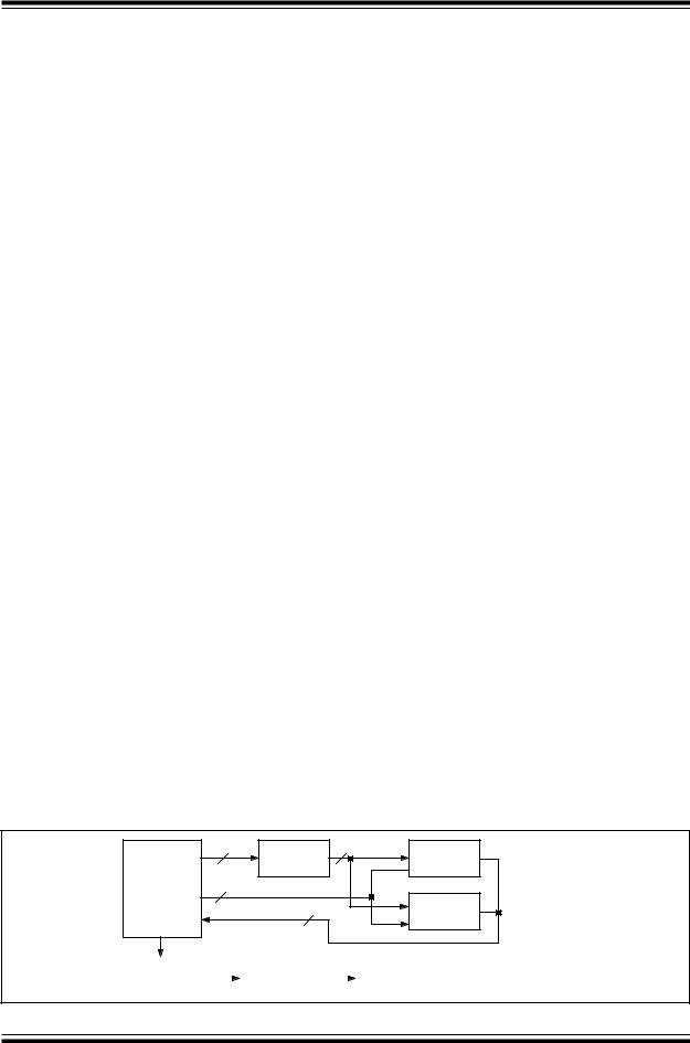
The hardware for this application note implements only the decompression algorithm, but the compression algorithm is also included in the firmware. A block diagram is shown in Figure 3 and the schematic is provided in Appendix E. The complete source code listing, including a block diagram, is given in Appendix F.
The board uses a PIC16C72, rated for 20 MHz operation, to control the speech decoding and output. The A/D (Ana- log-to-Digital) converter of the PIC16C72 is not used in this design. Two 27C512A EPROMs from Microchip Technology are used to store up to 32.768 seconds of ADPCM data. Each EPROM holds 65536 bytes. Each byte in the EPROM contains two ADPCM values. One second of speech requires 8000 ADPCM codes (8 kHz sample rate). Therefore, each EPROM holds (65536 x 2) / 8000 = 16.384 seconds of speech. A 16-bit up counter is used to clock data out of the EPROMs. This method uses only two I/O lines to control the counter and eleven I/O lines to read the EPROM data.
Speech regeneration is accomplished by using the Capture/Compare/PWM (CCP) module of the PIC16C72. The PWM module is configured for a period of 32 kHz. This allows each sample of the speech signal to be output for four PWM periods. The period is calculated by using the
following equation from Section 10.3 of the PIC16C7X Data Sheet (DS30390). From the following calculation, PR2 is set to a value of 155.
PWM period |
= |
[PR2 + 1] 4 Tosc |
|
|
|
|
(TMR2 prescale value) |
|
|
1 / 32 kHz |
= |
[PR2 + 1] 4 |
(1 / 20 |
MHz) 1 |
31.25 s |
= |
[PR2 + 1] 4 |
50 ns 1 |
|
156.25 |
= |
PR2 + 1 |
|
|
155.25 |
= |
PR2 |
|
|
The CCP module has the capability of up to 10-bit resolution for the PWM duty cycle. The maximum resolution of the duty cycle that can be achieved for a 32 kHz period can be calculated using the following equation from Section 10.3 of the PIC16C7X Data Sheet.
PWM duty cycle = DC<10:0> Tosc (TMR2 prescale value)
where DC<10:0> = 2x where x = bits of resolution
1 / 32 kHz |
= |
2x (1 / 20 MHz) 1 |
31.25 s |
= |
2x 50 ns 1 |
625 |
= |
2x |
log(625) |
= |
log(2x) |
log(625) |
= |
x log(2) |
9.3 |
= |
x |
A PWM duty cycle with up to 9-bits of resolution may be used with a period of 32 kHz. The upper 9-bits of each speech sample are used to set the PWM duty cycle (CCPR1L = sample<15:9>, CCP1CON<5:4> = sample<8:7>). This PWM speech signal is passed through a 4th-order Butterworth low pass filter with a corner frequency of 4 kHz. The low pass filter converts the PWM into an analog voltage level. Finally, the analog voltage level is amplified by a National Semiconductor LM386N-3 before entering the speaker.
Every 125 s (8 kHz) one ADPCM code must be converted into a speech sample for output to the PWM. This frame of 125 s relates to 625 instruction cycles for an external crystal frequency of 20 MHz. The ADPCM decode routine, EPROM reads and writes to the PWM must be accomplished within 625 instruction cycles.
FIGURE 3: APPLICATION HARDWARE BLOCK DIAGRAM
|
2 |
16-bit |
16 |
|
|
Counter |
27C512A |
|
|
|
|
PIC16C72 |
3 |
|
|
|
|
|
|
|
|
8 |
27C512A |
Butterworth |
|
|
Amplifier |
|
|
Speaker |
|
Power |
LPF |
|
|
|
|
|
Supply |
||
|
|
|
|
|
|
|
||
|
|
|
|
|
|
|
|
|
DS00643B-page 6 |
1997 Microchip Technology Inc. |