


SPRA118
1.1Introducing the Software Application
As previously stated, ADPCM is a complete digital transcoding process. According to the CCITT standard, if the PCM input bit flow is 64 kilobits per second (Kbps) (8 kHz sampling x 8-bit PCM word), you must process in real time, to produce a 40-, 32-, 24-, or 16-Kbps (8 kHz * 5, 4, 3, or
2-bit ADPCM word) output flow. A fixed-point digital signal processor (DSP) has an architecture which is capable of doing this. In particular, the new and very efficient TMS320C54x enables very rapid processing.
1.2Software Features
•16-, 24-, 32-, or 40-Kbps G.726 ADPCM (including G.721/G.723) in one single executable code, allowing rate switching during execution
•14-bit linear PCM allowed, in addition to A-law and m-law PCM input/output
•Possibility to implement several channels simultaneously in real-time processing (with time division sampling). This capability is possible during execution due to dynamic allocation of memory.
•8.3–10 millions of instructions per second (MIPS) requirement (encoder + decoder), depending on program configurations (rate/PCM law choice at reset or at each sample, linear PCM or log-PCM). As a comparison, G.721 (only 32 Kbps, while 40 Kbps requires additional instructions) ADPCM on C50x requires 10.5 – 12.5 MIPS
•About 1500 words of read-only memory (ROM) requirement (program: 680, data: 850)
•Less than a data page of random-access memory (RAM) per channel (less than 100 words)
•Independent code with memory mapping
•Viable software (all CCITT test sequences successfully verified)
•Clear program organization allows configuration and optimization for a specific application and portability
2 CCITT ADPCM Standard: Recommendation G.726
This section is a reproduction of the G.7261 Recommendation, section 1–3, developed by the International Telegraph and Telephone Consultative Committee (CCITT). The CCITT is a permanent organization of the International Telecommunication Union (ITU).
This section provides the principles and functional descriptions of the ADPCM encoding and decoding algorithms.
Two modifications have been made relating to the printed text of the recommendation. First, one detail concerning the 32-Kbps quantizer that takes one of 15 non-zero values (see section 2.4.3). Secondly, the transition detector equation has been corrected. In fact, the sampling index
TMS320C54x is a trademark of Texas Instruments.
1 This recommendation completely replaces the text of Recommendation G.721 and G.723 published in Volume III.4 of the Blue Book. It should be noted that systems designed in accordance with the present recommendation will be compatible with systems designed in accordance with the Blue Book version.
G.726 Adaptive Differential Pulse Code Modulation (ADPCM) on the TMS320C54x DSP |
5 |
SPRA118
seems to be (k–1), instead of (k) for yl and a2 (see section 2.4.12) 2.
2.1ADPCM Principle
The characteristics below are recommended for the conversion of a 64 Kbps A-law or m-law pulse code modulation (PCM) channel to and from a 40-, 32-, 24or 16-Kbps channel. The conversion is applied to the PCM bit stream using an ADPCM transcoding technique. The relationship between the voice frequency signals and the PCM encoding/decoding laws is fully specified in Recommendation G.711.
The principal application of 24and 16-Kbps channels is for overload channels carrying voice in digital circuit equipment (DCME).
The principal application of 40-Kbps channels is to carry data modem signals in DCME, especially for modems operating at greater than 4800 Kbps.
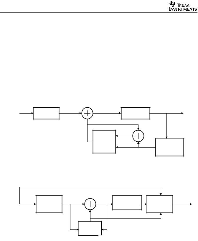
Simplified block diagrams of both the ADPCM encoder and decoder are shown in Figure 1.
64 kbits/s |
|
Input |
|
Difference |
|
|
|
PCM |
Convert to |
Signal |
+ |
Signal |
Adaptive |
ADPCM |
|
|
|||||||
Input |
Uniform PCM |
|
|
|
Quantizer |
Output |
|
|
|
|
– |
Signal Estimate |
|
|
|
|
|
|
|
Reconstructed |
+ |
|
|
|
|
|
|
|
|
||
|
|
|
|
|
Signal |
|
|
|
|
|
|
Adaptive |
|
|
Inverse |
|
|
|
|
Predictor |
|
+ |
|
|
|
|
|
|
|
Adaptive |
|
|
|
|
|
|
Quantized |
||
|
|
|
|
|
Quantizer |
||
|
|
|
|
|
Difference |
||
|
|
|
|
|
|
||
|
|
|
|
|
Signal |
|
|
|
|
|
|
a) Encoder |
|
|
|
|
|
Quantized |
Reconstructed – |
|
|
|
|
|
Difference |
|
64 kbits/s |
||
|
Inverse |
Signal |
Signal |
|
||
ADPCM |
Synchronous |
PCM |
||||
Adaptive |
+ |
Convert to PCM |
||||
Input |
|
Coding |
Output |
|||
Quantizer |
|
|
Adjustment |
|||
|
|
|
|
|||
|
|
+ |
Signal |
|
|
|
|
|
|
Estimate |
|
|
Adaptive
Predictor
b) Decoder
Figure 1. ADPCM Encoder and Decoder
2 While reporting printing errors, specification of IMAG in the COMPRES sub-block (G.726/section 4, not reproduced here), probably contains an error. In the case of LAW = 1 and IS = 1, IMAG = (IM –1) >> 1, and not (IM+1) >> 1.
6 G.726 Adaptive Differential Pulse Code Modulation (ADPCM) on the TMS320C54x DSP