3. Halftones
3.1 Image structure
3.2 To make out or ignore the screen
3.3. Halftone print model
3.3.1 Density of a halftone tint
3.3.2 Optical tone value increase
3.4 Effective tone scale range
3.5. Physical dot gain
3.6 Strategy of a screen ruling selection
Summary issues
Tests
3. Halftones
3.1. Image structure
Continuous tone (CT) original picture such as of a photograph, watercolor or oil painting is used to be sampled, i.e. divided onto tiny discrete spatial portions for producing the copy on a print or monitor. Tone value stays constant over unit image areas and if somehow changes but with no relation to tone variation within the corresponding sample on an original.
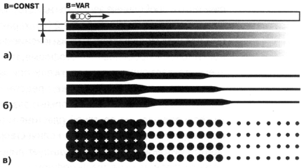
One dimensional, line-by-line rasterizing was inherent, for example, in b/w analogue TV. Image brightness was continuously varied just in the horizontal direction while across the line width it was subjected to the Gaussian low of electrons distribution in CRT beam with its integral intensity being dependent on the scene brightness averaged over the transmitted picture element (Figure 3.1a).
Print copy produced with the use of a line screen comprises the other example of one dimensional rasterizing where just the line width is defined by the reflectance of a CT original (Figure 3.1b).
The most of prints (Figure 3.1c) and encoded images are discrete in the both horizontal and vertical directions. However, contrary to analogue or digital TV image, the print copy element has just two tone levels defined by the optical densities Dp of a substrate or blank area (paper) and of a solid ink layer Ds. Similar bi-level synthesis is also inherent in the electro photographic, thermo transfer, LCD, ink jet, and some other imaging means complementing nowadays the traditional printing.
|
Figure 3.1 Image structures: of line fashion in b/w TV (a); with the line screen (b) or dots of variable area (c) in printing
|
The grey scale is reproduced by the bi-level graphic means in the so called autotype process with tone value control by the variation of inked and blank relative area without formal effect on the ink film thickness. This method had come in the industry over a century ago and allowed for the great increase of illustrative component in all kinds of editions. Previous way of the print plate manufacturing was rather labor consuming as far as had involved the art of manual engraving.
Autotype images were initially produced by photographing the CT original through the optical instrument - projection or contact screen onto the high contrast layer of short sensitivity range. Bi-level principle is widely used until now for the CT originals reproduction not only in traditional litho and relief printing but as well as in matrix, laser and LED toner based, ink jet and other kind of printers and digital presses. The common feature of all these techniques is still in creating the grey levels illusion by varying an ink coverage area, which was yet inherent in manual engraving.
Print elements may look as the lines of variable width (Figure 3.1b) or dots equidistantly placed over an image in orthogonal (Figure 3.1c), hexagonal or some other regular order. As far as only the area of such elements changes according to grey level of original (Figures 3.1b, 3.1c, 3.2a), these structures are, by analogy from electric signals processing, often named as the Amplitude Modulated - AM. Meanwhile, it would be more correct, following the same analogy, to call them as the Pulse Width Modulated [3.1].
Ink coverage can be also varied at keeping fixed the size of print elements with changing just the distance of their mutual location as shown in figure 3.2(c). Such print structures are used to be mentioned under the terms of FM (Frequency Modulated), dither, stochastic [3.2].
However, the tone rendition with the use of fixed size dots becomes rather problematic in the darker part of grey scale being limited by the printing process resolution. At assuming, for example, the dot size of 15x15 μm the width of the blank (indicated from the left in figure 3.2, c) should be less than 2.5 μm for three quartertones - 75% shades, i.e. physically non printable in a press run. So, such a structure can be taken just for some “idealistic” one. Meanwhile, the prints having non periodic microdots placement of the kind shown in figure 3.2 (b) are nowadays also related to FM ones [3.3].
|
Figure 3.2. Reproduction of the grey levels 25%: 50% and 75% with variation of:
Nevertheless, as is demonstrated by the same figure, they are in fact characterized by the combined AM/FM modulation. In the highlights (up to 25% tone values) and in shades (over 75%) there is yet the facility for dots and blanks to be placed in isolation from each other. However, each dot inevitably touches some an adjacent one in the middle tones (25% - 75%). It has place yet previous to printing, i.e. in the traditional plate making as well as at the latent image formation in a “laser” printer. This way created dot cluster comprises in fact the greater element of the casual form lacking the best printability, i.e. the potential of minimal error in target ink coverage on a print. Such parameters as frequency of dots placement or number of exposed spots can just related to the virtual bitmap of some software controlling the electronic dot generator. In this light, the multiple of non periodic, stochastic print structures, being developed with computer facilities since 1980ies, wasn’t appreciated by the industry practice because of ignoring the physical properties of the real print channel. Term halftone is predominantly used both as adjective and noun for characterizing the above discussed prints while the halftoning and screening are related to the process of converting the CT original into such kind of an image. It should be, however, noted that its use may create confuses in translation to some other languages. For example, the German halbton and Russian poluton, being literally the same as halftone, have nevertheless the quite opposite meaning of continuous tone and that’s why the English halftone is properly translated as the raster image to the both languages. From the other hand, raster and rasterizing are, in their turn, hardly related in English terminology to the halftone or halftoning but mostly used for designating the matrix of tiny microdots (sub elements) used for the type fonts, line matter and halftone dots formation in the Raster Image Processor – RIP.
3.2. To make out or ignore the screen? In terms of signal transfer techniques the halftone screen comprises an auxiliary, carrier frequency which is modulated by the image tone value to be brought onto a print through the plate making and press channel. This intermediate discrete presentation is further on subjected to demodulation (descreening) when visually perceived as the continuous tone distribution. According to sampling theory prepositions such image preserves all the spatial frequencies of an original which are at least twice fewer of the screen ruling (L). The latter is measured in lines per inch (Lpi) and comprises the basic, specific parameter of an image with halftone dots located within the orthogonal grid. The other spatial frequencies of imaging systems are used to be defined by such terms as sampling rate, resolution, scan lines density … measured in numbers of lines per a unit olength or viewing angle. There are mostly used the screen rulings within 75 – 200 Lpi range: (25 -75) - for wide format outdoor, “photo” wall paper and silk printing; (75 – 130) – newspaper and office printer images; (130-175) - magazines; (175-200) – advertizing pamphlets and art books; (200-250) – stereo and special printing. Frequency of halftones with non-orthogonal geometry can be estimated by some equivalent ruling measured, for example, for the hexagonal screen by the square root of dots amount on a unit print area. However, the frequency of halftones with irregular, FM structure is less definitely judged to, for example, non ambiguous compare their quality with AM prints. They are characterized just by the size of a used microdot (14 or 21 micrometers) chosen according to the available printing conditions. Nevertheless, such size correlates to the minimal dot of a regular, AM halftone which, in turn, comprises, as will be shown lower, the starting point for proper choice of a screen ruling. Autotype method explores the vision property to ignore separate dots and take them confluence, appreciate the lightness according to average reflectance over a unit print area which tone value is defined in percent by the relative ink coverage. All that creates the illusion of a continuous grey level image in spite of its bi level, binary microstructure. Acuity of normal vision allows for discerning up to 200 lines per inch. So, all the screens are distinguishable [1.8]. However, it’s more appropriate, in wider interpretation, to discuss the halftone structure ability to be noticed as far as the HVS actively participates in continuous appreciating the visually acute, discrete halftone structure [1.15]. Moreover, it ignores such structure frequency even selectively, depending on the print quality level and thereby behaving as the low pass filter of an adaptively varied threshold. Looking at the picture 175 Lpi in a magazine reader doesn’t notice the screen but appreciates twice lower 90 rods per inch repetition on a fence as the useful, informative data. In newspaper he, however, ignores the same frequency as belonging to the screen on behalf of digesting the illustrative data of at least, once again, twice lower, 45 cycles per inch. Not unimportant role in such selective perception plays the screen structure regularity. Rules of “game” in continuous tone simulation are changed for non periodic halftone. It’s easier for vision to ignore the periodic screen than the randomly placed microdots because of confuse in interpretation their sporadic cluster as the component of an auxiliary, image carrying structure or the some spot of an image itself. Selective perception of print frequencies is basically caused by the physical reasons obstructing the screen ruling increase up to the values which could be out the HVS response margins. It doesn’t allow for complete taking off the descreening problem as it has place in photography due to high granularity of its emulsions.1 Rightfulness of the print structure estimation in terms of its being “noticed” but not “discerned” is confirmed by the sincere surprise of some people unfamiliar with the trick of halftoning when their attention is put on their specific dot structure. It often happens that they had earlier used to appreciate them as continuous tone photographs. Works [3.4; 3.5] are devoted to the expert and theoretical evaluation the acuteness of screen structures and their textures in multicolor printing.
|
3.3 Halftone print models
In the context of further disclosure the term model assumes an analytical, graphic or other description of the process or device allowing for predicting its result at some changes of starting conditions or parameters. These models are often complemented by certain empirical data to improve their correlation with practical results. They are also helpful in creating the computer print simulators for press operators training.
Alternative to modeling is the greater precision but, however, labor and material consuming method of the multiple test trails providing the hard link between the input and output data.
Two basic models allowing for computation the optical density of a halftone according to its relative ink coverage (tone value) with taking into account the substrate and ink film densities are disclosed below.
3.3.1 Density of a halftone tint Basic local parameter of a halftone is the relative area S covered by ink within a print unit space. It’s defined by the ratio of indicated in figure 3.3 absolute areas of a dot S’ and a unit screen mesh Su. As far as the latter is equal to the square of screen period 1/L:
S = S’/ Su = S’ L2 3.1
|
Figure 3.3. Halftone dots in the orthogonal screen grid of 1/L period |
This parameter is mostly measured per cent and the last version of ISO 12647 names it tone value. Being averaged by vision or instrument aperture for multiple dots and blank spaces the reflection coefficient comprises:
ρ = Sρs + (1 – S) ρp, 3.2
where ρs and ρp are correspondingly the reflections of an ink solid and paper. By optical density definition ρs = 10-Ds and ρp = 10-Dp. So, the density Dprn of uniform halftone tint with tone value S can be calculated as
Dprn = lg [S·10-Ds + (1 – S)·10-Dp] 3.3
This equation published in 1936 by Sheberstov [3.6] and Murray, Davis [3.7] is strictly analytical. At the absence of dots S = 0 and hence D = Dp while for the solid ink layer, where S = 1.0 (100%), D = Ds. Its use undermines the preceded measurements of S, now with a digital microscope, and densities of paper Dp and ink solid Ds .
Nevertheless, this equation stays completely true at taking into account the following assumptions:
average reflectance is linearly dependent on areas of a dot and blank space;
ink film thickness doesn’t depend on the dot size;
illumination of the blank space interacts just with substrate;
light incident on the dot interacts just with an ink layer and part of substrate covered by dot.
Altogether, this model is mostly used for the estimation of dot gain as the difference between the tone value on a halftone transparency, plate or print and that initially assigned in digital file or bit map of a RIP. With three densities (D, Ds, Dp) being measured on control wedge patches the resulting tone value is for such purpose computed by the inverse to (3.3) equation
|
Sapp = (10-Dprn - 10-Dp) / (10-Ds - 10-Dp) |
3.4 |
3.3.2 Optical tone value increase
Subscript index for Sapp designates in above equation this value as an apparent because the measured tint density D occurs in the most cases to be greater of predicted by (3.3). Correspondingly darker the print looks for a viewer and the dot size computed by (3.4) becomes as if greater of the measured one. All that may mean that less light is reflected than it’s predicted by the model. Such discrepancy between the computed and practical data is called the optical dot gain.
It takes place due to the partial trap by print element edges of light incident on a blank space after scattering within the substrate. The beam 1 indicated in figure 3.4 relates to such share of not returned to a viewer illumination.
It may seem that this is somehow compensated by the reflectance complemented by the beam 2 of some opposite behavior of entering into substrate through the ink layer but exiting from a blank space because of scattering. However, contrary to beam 1, this one had been greatly weakened at its initial penetration to substrate through the ink and therefore compensates just the tens part of light loss at assuming, for example, the ink film density 1.0 unit.
|
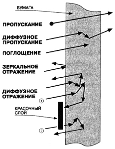
Figure 3.4. Optical dot gain is caused by the trap of light (beam 1) entered into a paper in the blank area and diffused under the edge of a halftone dot.
Yule and Nilsson [3.8] suggested the correction coefficient n to make model result closer to factual data:
|
Dprn = n·lg [S·10-Ds /n + (1 – S)·10-Dp /n] |
3.5 |
Being purely empirical, this amendment considers the effect of several physical and geometric factors on this phenomenon.
Edge width, which traps the diffused light, has the absolute value depending just on substrate properties and its share increases with dot reduce as indicated in figure 3.5. That’s why it’s used to vary the n factor from 1.0 to 3.0 within the range of screen rulings.
This
edge share depends also on the dot and blank perimeter. In such, and,
as it’ll be shown later, some other aspects their round form is
preferable as having the minimal perimeter for predefined area.
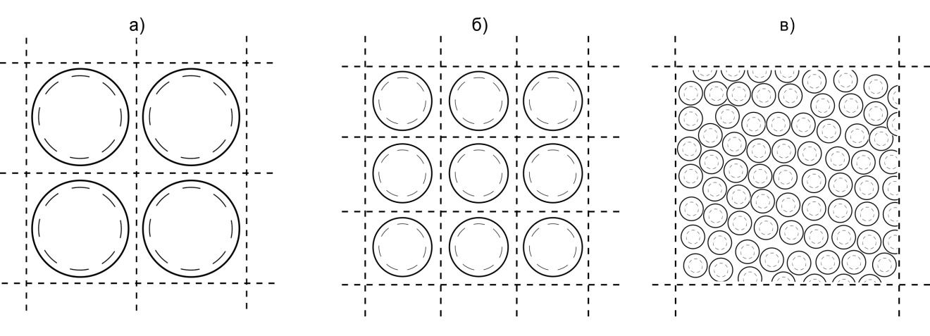
Figure 3.5. Halftone dot edge, which captures the light scattered in blank space, is constant in its width. For the same tone value its area share increases in square-low to the screen ruling growth (a, b) and is essentially greater in FM screening (c) or with the use of perforated, “concentric” dots.
The geometry changing with variation of ink coverage is also meaningful. With tone value increase the dot perimeter grows up to the moment of its contacting the adjacent ones, i.e. when it’s converted into perimeter of isolated blank spaces. So, the form and extreme point position on the optical tone increase characteristic depend on the dot geometry as illustrated in figure 3.6 by the curves resulting from Gustavsons’ modeling [3.9]. Some other examples of the middle tone screen/dot geometries are given in figure 3.7.
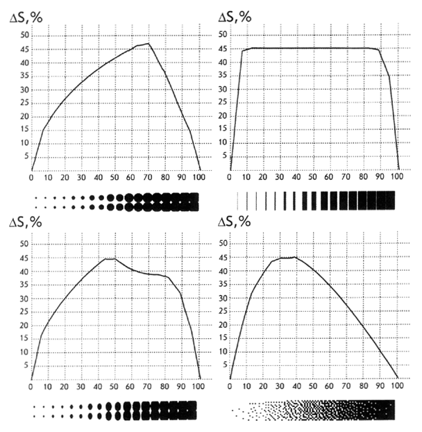
Figure 3.6. Form and extreme point position on the tone optical increase characteristic depend on the dot and screen structure geometry
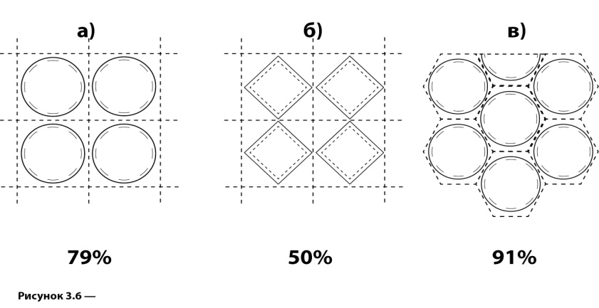
Figure 3.7. Maximal optical, as well as physical, dot gain has place when the neighboring print elements touch each other
It’s seen from these pictures that the square dots placed in chessboard order give the maximal increase at 50% tone value, for the round ones it happens at 79% and shifts to yet darker region taking the meaning of 91% when the round dot is inscribed into unit mesh of a hexagonal screen. Halftoning with the random, stochastic location of fixed size microdots within the orthogonal matrix moves this maximum to lighter area as far as the touch starts to occur at about 25%.
The inverse to equation 3.5 ink coverage computation
|
Sph = (10-Dprn /n - 10-Dp /n) / (10-Ds /n - 10-Dp /n) |
3.6 |
gives the Sph of the physical dot area as corresponding to its factual size excluding the optical dot gain from D measured value.
Gradual growth of process resolution had increased the Yule and Nilsson effect on grey scale reproduction. Print element reduction to 14 – 21 micrometers is accompanied by the qualitative changes in ink transfer and fastening. Contrary to periodic halftones, such small, unstable elements random placement results in volatile ink coverage geometry for they present here not only in the highlights and darkest areas but along the whole grey scale.
The development of analytical models taking into account the specific of light – ink layer – paper interaction is continued. Recommendations of n factor choice and model modifications considering several peculiar print properties were later suggested to get more accurate prediction [3.10 - 3.13]. Investigations had, for example, proved that certain kind of mottle on the halftone tints is caused by the fluctuation of optical dot gain because of the paper optical properties non uniformity [3.14 - 3.15].

