

64 Wet-Steam Turbines for Nuclear Power Plants
The water drops leave the nozzle channel with a velocity, c', which is less than the steam velocity, c", achieved due to expansion. Even if the exit angles of steam flow and liquid motion coincided, the water drops leaving the nozzle channel with a lower velocity would move in a different direction relative to the rotating blades, and would hit the back of the turbine blade at an angle of δβ1 = β 1
β 1 (Fig. 2–17). As a result, a retarding torque develops that acts on the rotating wheel.This retarding torque increases with the increase of the circumferential speed, u, reduction of the water velocity, increase of the steam wetness, and growth of water drops hitting the rotating blades. All of these values vary along the height of the stage, and the stage efficiency is affected by factors that, in turn, remarkably depend on the turbine’s steam path design features, peculiarities of the wet-steam flow, the wetness dispersion, and so on.
Fig. 2–17. Velocity triangles of a wet-steam turbine stage for steam and water
This intricate, multifactor influence is difficult to treat theoretically or to model numerically. In many respects, it is more productive and reliable to investigate these phenomena experimentally, and even the best existing theoretical and computational models need for their verification reliable experimental data on the structure of wet steam flowing in real turbine stages and multistage turbines.
www.EngineeringBooksPdf.com
|
|
|
|
|
The Thermal Process in Wet-steam Turbines 65 |
|||
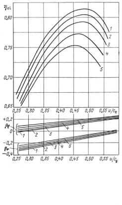
Some results |
of |
bench |
|
|
||||
tests for a model turbine |
|
|
||||||
stage with variations in the |
|
|
||||||
initial |
steam |
temperature |
|
|
||||
and wetness are shown in |
|
|
||||||
Figure 2–18. The initial wet- |
|
|
||||||
ness was created by a spray |
|
|
||||||
providing |
relatively |
large |
|
|
||||
drops, with an average di- |
|
|
||||||
ameter |
of |
about |
50mkm. |
|
|
|||
This diminished |
the |
stage |
|
|
||||
efficiency |
throughout the |
|
|
|||||
studied velocity ratio range, |
|
|
||||||
simultaneously |
|
reducing |
|
|
||||
its optimal |
value. Increases |
|
|
|||||
in wetness resulted in in- |
|
|
||||||
creased stage reactivity (re- |
|
|
||||||
action degree). This is pre- |
|
|
||||||
dominantly explained by a |
|
|
||||||
greater increase in the flow |
Fig. 2–18. |
Changes in the internal |
||||||
amount factor for the nozzle |
||||||||
efficiency and reaction degree for tip and |
||||||||
row, µ 1 , compared with that |
||||||||
root zones ( |
t and r, respectively) related |
|||||||
for the rotating blades, µ2, as |
to velocity ratio and initial steam wetness |
|||||||
well as |
by |
the |
increase in |
for an experimental turbine stage (1: ∆t0 |
||||
the exit angle, |
1 , with the |
= 150 °C; 2: y0 = 0.005; 3: y0 = 0.02; 4: y0 = |
||||||
0.042; 5: y0 = 0.068) |
||||||||
degree |
of |
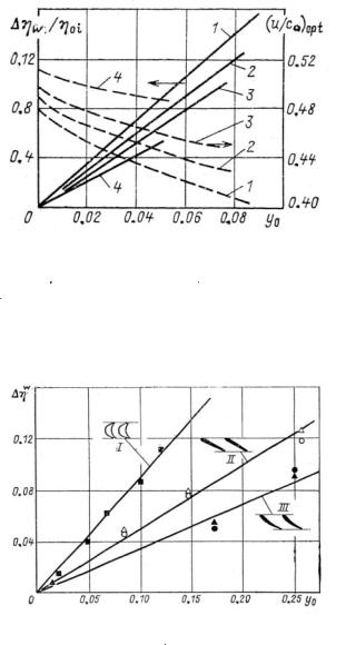
wetness. Figure |
||||||
Source: B. M.Troyanovskii, G.A. Filippov, and |
||||||||
2–19 demonstrates specific |
||||||||
A. E. Bulkin31 |
|
|||||||
changes in the efficiency for |
|
|
||||||
model stages with different
median diameter–to–height ratios depending on the initial wetness. The smaller the stage height, the more intensely the wetness diminishes the stage efficiency, because a greater part of the moisture precipitates on the wall surfaces, forming thin water films. These films then divide into drops, but they do not have time to accelerate in the gap between the nozzles and rotating blades and to a large degree hamper the rotating blades. For such stages with a relatively small height, the optimal velocity ratio more noticeably decreases with the increase of the steam wetness.The wetness influence also differs for different blade profiles. It is greater for blade rows with larger turn angles and less for the plane profiles that are characteristic for the tip sections of blades with large length-to-median diameter ratios (Fig. 2–20). 32
www.EngineeringBooksPdf.com
66 Wet-Steam Turbines for Nuclear Power Plants
Fig. 2–19. Changes in optimal velocity ratio and internal stage efficiency for turbine stages with different median–diameter-to-height ratios, depending on
initial wetness (1: d/l = 27, l1 = 15 mm; 2: d/l = 16, l1 = 25 mm; 3: d/l = 8, l1 = 48 mm; 4: d/l = 2.7, l1 = 207 mm)
Source : B. M.Troyanovskii, G.A. Filippov, and A. E. Bulkin33
Fig. 2–20. Influence of initial wetness on changes in efficiency related to different rotating blade profiles (I: u/c0 = 0.5; II and III: u/c0 = 0.7)
Source : B. M.Troyanovskii, G.A. Filippov, and A. E. Bulkin34
Calculations of the turbine steam path fulfilled consecutively stage-by-stage must take into consideration the change in steam wetness after the stages due to internal moisture separation. The actual initial wetness for the next stage is less than the outlet wetness after the preceding stage, indicated by y2 by the value of
www.EngineeringBooksPdf.com

The Thermal Process in Wet-steam Turbines 67
∆y = × y2, where is the separation factor, or separation efficiency. Its value depends on various physical, geometrical, and design characteristics of the stage, and on the type of moisture separation used in the stage. According to some experimental data, for typical internal moisture separation devices, a stage’s separation efficiency,
, can vary between 0.02 and 0.2, increasing along the steam path during the steam expansion process.35 Due to moisture separation, the initial point of the steam expansion process for the stage shifts along the initial pressure isobar by ∆y , as seen in Figure 2–2 for the LP stages, and the entire steam expansion line assumes a zigzag configuration. Because a certain portion of the steam is captured and removed with the water, the steam flow amount for the stage is additionally decreased. According to GE, this additional steam flow loss amounts to about 0.5%.36
The total influence of wetness on the wet-steam turbine’s stage efficiency is often approximated by various semi-empirical equations. In so doing, the wet-steam turbine’s stage efficiency is related to the efficiency of the same stage as if it worked with superheated steam. One of such semi-empirical equations has been proposed as follows: 37
ηst wet = ηst |
s.h. × [1– 2 × (u/c0) × (k y0 + k2∆y)], |
(2.6) |
where y = y2 |
y0 is the increase in wetness for the stage, u/c0 |
is the |
velocity ratio for the stage, and k1 and k2 are empirical coefficients, where k2 0.35, and the value of k 1 is supposed linearly dependent on the share of coarse-grain drops, λcg
k1 0.8 + 0.5 × λcg |
(2.7) |
In turn, the value of λcg depends on many steam path characteristics. This dependence is also described by various semi-empirical equations. So, for example, for multistage wet-steam turbines, it is advised to take this value in proportion to the number of preceding stages working with wet steam, zw 38
λcg = 0.07 × (zw + 1) × (0.5 – 0.94 × lnp0) |
(2.8) |
www.EngineeringBooksPdf.com
68 Wet-Steam Turbines for Nuclear Power Plants
For stages with slightly superheated steam at the entrance, when the steam expansion line crosses the saturation curve, including the first HP stage, their efficiency is proposed to count as
ηst wet = ηst s.h. × (1 – ζsc), |
(2.9) |
where the loss due to wetness corresponds to the subcooling loss, and can be calculated with the help of Equation 2.3b as = p2/p0s where p0s is the pressure at the point where the steam expansion line crosses the saturation curve.
The overall effect the steam wetness has on wet-steam turbines’ efficiency has been empirically proven in numerous bench and field tests at wet-steam turbines of diverse design features. Of particular interest is a greater sensitivity to the wetness of the stages with shrouded, reaction-type rotating blades compared with unshrouded (free-standing) blades (Fig. 2–21). Results of tests performed by GE with low-speed impulse-type turbine stages feature, in particular, rapid declines in efficiency with the first appearance of wetness (mean values up to 0.02), which points out the significance of energy losses with steam subcooling in the process of phase transition (Fig. 2–22). Nonlinear dependencies between energy losses (or decrease in efficiency) and median wetness were also found in other field experiments. 39
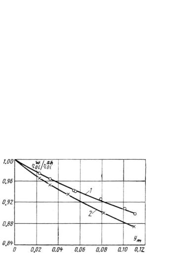
Fig. 2–21. Influence of wetness on efficiency for reaction-type turbine stages (1: steam path with shrouded rotating blades; 2: steam path with unshrouded rotating blades)
Source : B.M.Troyanovskii, G.A. Filippov, and A.E. Bulkin40
www.EngineeringBooksPdf.com
The Thermal Process in Wet-steam Turbines 69
Nevertheless, as the first approximation, the influence of wetness on turbine efficiency is often considered to be linear, and can be described in the simplest form by the Baumann rule:
ηst wet = ηst s.h. × (1 – a ym), |
(2.10) |
where ym = (y0 + y2)/2 is the average steam wetness for the stage or stage group, and a is an empirical coefficient known as the Baumann factor. Various experiments carried out on different types of turbines provide a range of values for a, varying from 0.4 to 2.0, but this factor is usually assumed equal to 1.0, according to Karl Baumann himself.41 This assumption takes into account not only the previously mentioned energy losses, but also working-fluid mass losses, because the steam converted into water no longer performs work in the considered and subsequent turbine stages. Originally based on experiments carried out on steam turbines in 1921, 42 the Baumann rule has remained as a long-lived empirical rule in the history of turbomachinery. Although the Baumann rule is convenient to apply and in many cases quite commensurate with experimental data as shown in Figure 2–22, it actually provides little insight into the physical nature of wetness as it relates to turbine efficiency. It takes into account the total quantity of moisture in the wet-steam flow, but ignores its structure. At the same time, according to the theory of two-phase wet-steam flow, possible variations in the flow structure can be even more important and influential than the total moisture quantity.
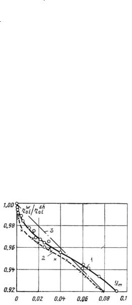
Fig. 2–22. Influence of wetness on efficiency for impulse-type turbine stages
(1: HP steam path; 2: LP steam path; 3: Baumann rule)
43
Source : M. J. Mwwwoore .EngineeringBooksPdf.com
70 Wet-Steam Turbines for Nuclear Power Plants
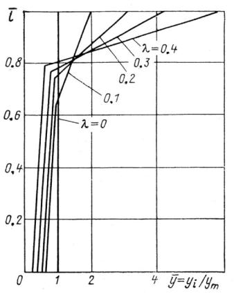
All of the previously mentioned approaches are mainly employed for plain steam path calculations. For turbine stages with relatively long blades, the steam expansion process is calculated for a few sections (individual streams) across the stage height. In doing so, the lengthwise wetness distribution following the preceding stage is calculated based on the initial average wetness (for the relevant stage) and the coarse-grain wetness share—as shown in Figure 2–23, for example. It is also conditionally accepted that this share for each section changes in proportion to the total wetness in the relevant section, but cannot be greater than 0.9. As seen in Figure 2–23, it is assumed that the greater the drop size, the more uneven the wetness distribution along the blade length becomes, acquiring an L-shaped appearance.
Fig. 2–23. Distribution of exit wetness along the height of an individual stage, depending on the coarse-grain wetness portion
Source : B. M.Troyanovskii, G.A. Filippov, and A. E. Bulkin44
www.EngineeringBooksPdf.com
The Thermal Process in Wet-steam Turbines 71
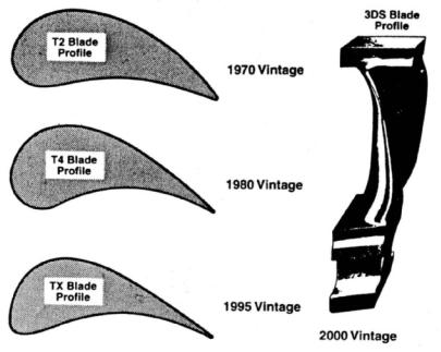
Most turbine developers currently calculate and design turbine steam paths with the use of fully three-dimensional (3-D) computational techniques.45 These 3-D computational techniques are aimed at reducing the secondary energy losses in the turbine stages, along with profile losses. This has led to the development and use of new, sometimes nontraditional, blade profiles, and the creation of 3-D, meridionally profiled steam paths using not only twisted and tapered, but also bowed (curved) and leaned (inclined) vanes and blades.The evolution of reaction-type integrally shrouded HP blades for Siemens turbines shown in Figure 2–24 and Figure 2–25 demonstrates the effect of replacing a classical vane with a curved and inclined one in the last LP stage for Asea Brown Boveri (ABB) turbines.
Fig. 2–24. Development of reaction-type, integrally shrouded blades for Siemens turbines
Source : H. Oeynhausen,A. Drosdziok,W. Ulm, and H.Termyuehlen46
www.EngineeringBooksPdf.com
72 Wet-Steam Turbines for Nuclear Power Plants
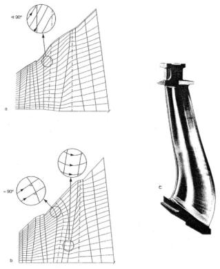
Fig. 2–25. Changes in meridional steam flow behavior in LP stages of
ABB turbines, due to using 3-D, bowed, and inclined vanes in the last stage (a: classical vane; b: bowed and leaned vane; c: model of advanced 3-D vane)
Source :A. P.Weiss47
Curved and inclined blades, with the angle of inclination decreasing from the blade root to its periphery, were first proposed and investigated at the Moscow Power Engineering Institute by G.A. Filippov and H. Chungchi in 1962. 48 Nowadays, these saber-like vanes and blades have gained widespread acceptance in steam turbines built by almost all the world’s major turbine manufacturers.Although initially these vanes and blades were predominantly intended only for LP stages with a large length-to-mean diameter ratio, now such blading is frequently employed in the HP and IP stages.
Advanced computational fluid dynamics (CFD) calculations have also been applied to improve the turbine path in nonbladed areas, with the use of special baffles, razors, and screens to avoid backflows and vortex formation and to reduce extreme energy and pressure losses.
www.EngineeringBooksPdf.com
Next Page
The Thermal Process in Wet-steam Turbines |
73 |
Among other novelties of turbomachinery, of importance is Siemens’ initiative to design the turbine steam path optimizing the reaction degree for each stage individually, varying it in a wide range from 10% to 60%.49 Whereas Siemens has traditionally designed their turbines in a reaction-type mode, GE has traditionally produced impulse-type turbines. Nevertheless, GE currently suggests a “dense pack” turbine design methodology, when the steam path is designed with an increased number of stages and increased reaction degree.50 In so doing, GE arrived at nearly the same intermediate design decision as Siemens did, but from another direction. The 2000s-vintage turbines also feature reduced steam leakage due to advanced steam gland seals. All of these features make modern turbines much more efficient compared with those of the 1990s. 51
Even though the mentioned design approaches were mainly developed for fossil fuel power plants, they have been integrated into modern wet-steam turbine design as well. However, the development of wet-steam turbines and computation of their steam paths, in particular, has demanded a better comprehension of moisture behavior in the steam path, as well as the motion of water drops and films with regard to actual turbine design features. Special methods for calculating the wet steam structure have had to be developed. In contrast to old flow analysis techniques, which could only deal with ideal gases, new 3-D calculation methodologies analyze nonequilibrium condensation flows that take into account different steam wetness conditions and phase variations, allowing the designers to estimate the flow rate, loads, and losses of individual turbine stages much more accurately.52 Nevertheless, these methodologies require further development and improvement.
The mentioned analytical tasks were simultaneously taken up by different groups of prominent scientists in the mid-1970s. 53 Calculation methods for those years as applied to multistage wet-steam turbines were mainly based on extremely simplified notions and did not take into consideration a number of important factors.The shortage of reliable experimental data concerning the structure of the wet-steam flow in actual turbine steam paths was also noted, and developers looked forward to substantial progress in all of the turbine steam path characteristics based on such experimental data. Almost 20 years later, a scientist of a new generation spoke in front of the von Karman Institute for Fluid Dynamics’ audience, saying that “our
www.EngineeringBooksPdf.com