

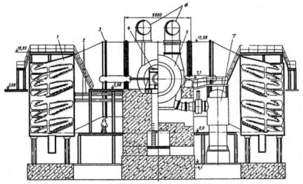
Fig. 3–11 Longitudinal section of MHI’s 900-MW–class low-speed wet-steam turbine
Source: By courtesy of Mitsubishi Heavy Industries
125 gnesiD
www.EngineeringBooksPdf.com
Plants Power Nuclear for Turbines Steam-Wet 126
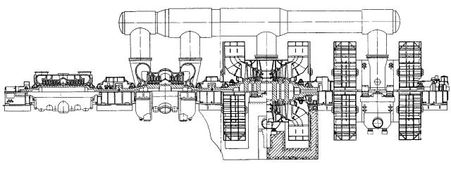
Fig. 3–12 Longitudinal section and general view of GEC Alsthom’s 630-MW 3,000-rpm wet-steam turbine for the double-turbine Sizewell-B nuclear power unit
Source: J.A. Hesketh and J. Muscroft23
www.EngineeringBooksPdf.com
Design 127
to stress corrosion cracking (SCC), especially in the Wilson (phasetransition) region. Advanced disk technology, such as that developed by Siemens, is needed to prevent these rotors from experiencing SCC. As a palliative measure, low-speed LP rotors are sometimes manufactured as solid units with shrunk-on disks added at the very last stages, which allows for a reduction in the size of the forged piece.
The gain in efficiency achievable for half-speed turbines, as compared to full-speed turbines, was demonstrated in efficiency calculations fulfilled by Turboatom as applied to their 1,000-MW 1,500-rpm turbine. It was compared with a similar high-speed (3,000 rpm) turbine designed by LMZ.24 Both of these turbines were intended to work with PWR-type reactors VVER-1000s, with a main steam pressure of 5.9 MPa (853 psi). The Turboatom K-1000-60/1500-2 turbine comprises a double-flow HP cylinder and three LP cylinders, with a 1,450-mm (57-in) LSB providing an annular exhaust area of 18.9 m2 (203.4 ft2) per flow (Fig. 3–13).25 All of the rotors are made welded. The LMZ K-1000-60/3000 turbine includes one double-flow HP cylinder and four LP cylinders, with the LSB made of titanium alloy with a length of 1,200 mm (47 in) and an annular exhaust area of 11.3 m2 (121.6 ft2) per flow (Fig. 3–14).26 This turbine also differs from all of the previously mentioned ones in the location of its LP cylinders—instead of the more common “train” arrangement (with all of the LP cylinders located in series between the HP cylinder and the generator), it uses a “butterfly” scheme, with the LP cylinders symmetrically located on both sides of the HP cylinder.This provides some advantages in the arrangement of the turbine auxiliaries and somewhat decreases the pressure drops in the LP crossover pipes. As with the Siemens 1,000-MW high-speed turbine, the LP rotors are solid (Fig. 3–7). Initially, these rotors were designed to be welded, but creating them as solid units helped to ensure their greater strength.
Calculations showed that due to the larger total exhaust area (113.4 m2 vs. 90.4 m2) and, as a result, smaller energy losses with the exit velocity (28.0 kJ/kg vs. 45.0 kJ/kg, at the steam back pressure of 4 kPa [0.58 psi]), the low-speed 1,000-MW Turboatom turbine could be more efficient by about ∆η/η = 4%.27 The acceptance tests of this turbine at the Zaporozhe nuclear power plant in Ukraine proved a gross thermal efficiency of 34.8% at the MCR of 1,010 MW.28
www.EngineeringBooksPdf.com
Plants Power Nuclear for Turbines Steam-Wet 128
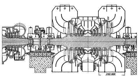
Fig. 3–13. Longitudinal section of the HP cylinder and one of three LP cylinders of Turboatom’s 1,000-MW 1,500-rpm K-1000-60/1500-2 wetsteam turbine
Source: By courtesy of Turboatom
www.EngineeringBooksPdf.com
Design 129
Fig. 3–14. Longitudinal section of a half of the HP cylinder and one of four LP cylinders of LMZ’s 1,000-MW 3,000-rpm K-1000-60/3000 wetsteam turbine
Source : By courtesy of LMZ
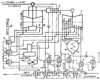
According to Turboatom, the larger overall dimensions of the lowspeed turbines provide less pressure drops in the turbine’s nonbladed areas. In addition, the larger size also allows designers to increase uncontrolled steam extractions in order to cover the heating demands of adjacent dwelling and industrial regions. This idea materialized in the next version of Turboatom’s low-speed 1,000-MW turbine series, the KT-1070-60/1500-3. 29 It was designed with increased uncontrolled bleedings for a heating output of up to 5,000 GJ/h (4.74 billion Btu/h).The schematic diagram of this turboset is shown in Figure 3–15.The turbine is designed with three cylinders, including two LP cylinders, and a 1,650-mm (65-in) LSB. The increased steam
www.EngineeringBooksPdf.com
130 Wet-Steam Turbines for Nuclear Power Plants
extractions can be also used for desalination of seawater. Although sacrificing approximately 20% in electric output, a steam turbine such as the K-1070-60/1500-3 can provide approximately 15,000 m3/h of desalinated water, that is, about 100,000 m3/day if the bleedings are open only at night during the power consumption ebbs.30
Fig. 3–15. Schematic diagram of Turboatom’s KT-1070-60/1500-3 1,000-MW wet-steam turbine with four-stage network water heating to 180°C (1: HP cylinder; 2: MSR; 3: two LP cylinders; 4: condensers; 5: first-stage condensate pumps; 6: steam ejector cooler; 7: second-stage condensate pumps; 8: LP regenerative heaters; 9: deaerators; 10: turbine-driven feed water pumps; 11: HP feed water regenerative heaters; 12: to reactor’s steam generators;
13: network water heaters’ drain coolers; 14: network water heaters; I: first steam bleeding; II: second steam bleeding, etc.)
Source : M.A.Virchenko, B.A.Arkad’ev, and V.Y. Ioffe31
www.EngineeringBooksPdf.com

Design 131
Modern steam turbines are thoroughly calculated and designed with the use of contemporary methods of computational fluid dynamics (CFD), applied not only to the primary steam paths of the turbines, but also to the nonbladed areas, such as steam admission and extraction chambers, crossover pipes, exhaust ports (hoods), and so on.The efficiency of “nuclear” wet-steam turbines is more sensitive to energy losses in the LP cylinders, because their portion in the turbine output is much more than that of superheated-steam reheat turbines. Hence, the LP exhaust ports of nuclear turbines need special attention to maintain efficiency. At the same time, their design optimization is especially intricate, because of high exit steam velocities after the LSB, significant unevenness of this velocity field across the steam stream, and significant changes in the steam flow patterns depending on the steam flow amount (or turbine load).
The exhaust port efficiency can be characterized by a correlation between the steam pressure values at the port’s exit and entrance (that is, in the condenser, pc, and after the LSB, p2, respectively) and the energy losses with the exit steam velocity, c2.This value, called the relative decompression, or hydraulic resistance factor, can be either negative or positive. It is estimated as follows:
ξdec = 1 - ζ = (pc p2) /(c2 2/2 v2)
where v2 is the specific volume of steam after the LSB. If the value of ζ is less than 1.0 (that is, pc > p2 and ξdec > 0), this indicates that the energy loss with the exit velocity is partially compensated in the exhaust port. But if ζ > 1.0, pc < p2, and ξdec < 0, the exhaust port energy loss is added to that with the exit velocity. For typical LP cylinder exhaust ports, ζ is commonly close to 1.2.The use of a special diffuser configuration for the LP exhaust port makes it possible to decrease this value to approximately 1.0 or even less.32
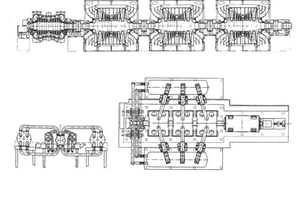
Turboatom’s family of low-speed 1,000-MW turbines also includes the K-1000-60/1500-1 turbine, which differs from the previously mentioned models by the use of a separate double-flow IP cylinder and side condensers (Figs. 3–16 and 3–17).These two design concepts were preliminarily worked out at a model 500-MW low-speed turbine, which was subjected to detailed field tests at the pilot double-turbine Novovoronezh Unit 5 with a prototype VVER-1000 reactor (Fig. 3–18).
www.EngineeringBooksPdf.com
Plants Power Nuclear for Turbines Steam-Wet 132
Fig. 3–16. Longitudinal section of Turboatom’s K-1000-60/1500-1 1,000-MW 1,500-rpm wet-steam turbine with IP cylinder and side condensers
Source: By courtesy of Turboatom
www.EngineeringBooksPdf.com
Design 133
Fig. 3–17. Rear-view and cross-section of the LP cylinder for Turboatom’s 500and 1,000-MW 1,500-rpm wet-steam turbines with side condensers (1: condenser; 2: flexible joint; 3: sylphon; 4: bearing casing; 5: LP cylinder’s casing; 6: crossover pipes; 7: LP regenerative heater)
Source : By courtesy of Turboatom
All of the rest of previously mentioned turbines, as well as the overwhelming majority of all large steam turbines used in both nuclear and fossil fuel power plants, are equipped with basement condensers. When the exhaust steam leaves the LSB, it disperses in both radial and axial directions and then turns to reach the condenser. Simultaneously, the steam streams, which have been annular in cross section up to this point, develop a rectangular cross section. This process is accompanied by the creation of vortices, rotation of the exhausted steam, and additional pressure drops (see Fig. 5–11). With side condensers, as for the considered K-500-60/1500 and K-1000- 60/1500-1 turbines, a space angle of turning for the steam stream is less than that for turbines with basement condensers that results in more even steam conditions after the LSB. Bench tests for the mentioned turbines with side exhaust ports showed a value of ζ close to 0.7.33 Field heat-rate performance tests at the Novovoronezh, South Ukraine, and Kalinin nuclear power plants completely confirmed the higher efficiency ratings of turbines with side exhaust ports. In addition, the side condensers make the turbine foundation simpler and stiffer and allow for a decrease in the overall size of the turbine hall.
www.EngineeringBooksPdf.com

Plants Power Nuclear for Turbines Steam-Wet 134
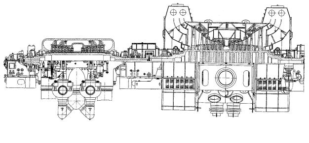
Fig. 3–18. Longitudinal section of Turboatom’s 500-MW low-speed wetsteam turbine with IP section and side condensers
Source: By courtesy of Turboatom
www.EngineeringBooksPdf.com