

84 Wet-Steam Turbines for Nuclear Power Plants
Fig. 2–35. System for sampling primary condensate (a) and laser probe
(b) for investigating corrosive properties of wet steam on a model turbine (1: turbine rotor; 2: turbine casing; 3: probe and sample trap; 4: turbine stage; 5: sample tank; 6: helium-neon laser; 7: laser power supply; 8: head of the laser probe; 9: photomultiplier power supply; 10: photomultiplier; 11: analog- to-digital transformer; 12: interface; 13: computer; Jx : radiation intensity; Ix : current signal)
Source : O. I. Martynova, O.A. Povarov,T. I. Petrova, et al.68
www.EngineeringBooksPdf.com
The Thermal Process in Wet-steam Turbines |
85 |
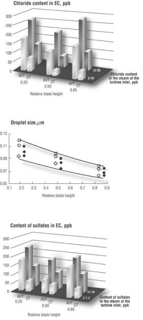
Fig. 2–36. Content of chlorides (a) and sulfates (c) in primary condensate; variation of droplet size over the stage height for different impurity levels in steam at the turbine inlet (b)
Source : O. I. Martynova, O.A. Povarov,T. I. Petrova, et al.69
www.EngineeringBooksPdf.com
86 Wet-Steam Turbines for Nuclear Power Plants
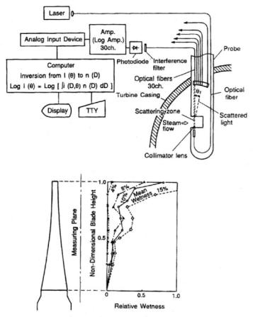
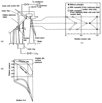
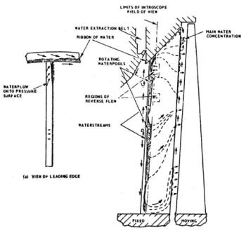
Japanese scientists of Toshiba employed a combined approach to investigations of wet-steam flow as applied to a new 40-inch titanium LSB developed for the rotation speed of 3,600 rpm and 52-inch steel LSB for low-speed turbines.70 The steam wetness and water drop size distribution along the stage height were measured with the use of an optical system, as shown in Figure 2–37a. For the measurement, a parallel laser beam was radiated into the steam flow, and the light scattered from the drops was transmitted through 30-channel optical fibers to photodiodes. Computerized analysis of the scattered light intensity distribution enabled calculation of the drop size and moisture mass distribution; some results of the wetness measurements are shown in Figure 2–37b. The tests simultaneously comprised measuring the quantity of water removed from the stage via suction slots on the surfaces of the hollow vane, as well as the relative erosion rate of the LSB’s inlet edge (Figs. 2–38a and c). In addition, the steam flow can be viewed through a boroscope—a kind of endoscope (Fig. 2–39a). In order to avoid direct contact with the steam, the boroscope was enclosed in a protective sheath (Fig. 2–39b). It was introduced into the steam path downstream of the last stage vane row to observe the steam flow and water motion on the convex vane surface (Fig. 2–39c). Many water films and rivulets stripped off from the outlet edge and atomized in the steam stream were seen along the upper half of the blade height, but these events were relatively rare in the lower half.
www.EngineeringBooksPdf.com
The Thermal Process in Wet-steam Turbines |
87 |
Fig. 2–37. Schematic diagram of steam wetness measurement system (a); wetness distribution over the stage height at a model turbine outlet (b)
Source :T. Sakamoto, S. Nagao, and T.Tanuma71
www.EngineeringBooksPdf.com
88 Wet-Steam Turbines for Nuclear Power Plants
Fig. 2–38. Schematic diagram for measuring water quantities withdrawn through suction slots on surfaces of the hollow vane (a); pressure distribution along the vane profile (b); relative erosion rate of the blade inlet edge (c)
Source :T. Sakamoto, S. Nagao, and T.Tanuma72
www.EngineeringBooksPdf.com

The Thermal Process in Wet-steam Turbines |
89 |
Fig. 2–39. Boroscope probe (a); inserted into the model turbine steam path (b); behavior of water flow at outlet edge of the nozzle vane (c)
Source : H. Kawagishi, S. Nagao, and T.Yamamura73
www.EngineeringBooksPdf.com
90 Wet-Steam Turbines for Nuclear Power Plants
According to endoscopic observations by different researchers, the actual motion of water across the stationary, non-rotating parts of the steam path (nozzle vanes, diaphragm, and casing walls) composes an intricate picture (Fig. 2–40).The pattern to a great degree depends on the pressure and steam-flow fields around the stage, but in many respects, it is rather disordered, although there exists some welldefined radial water motion—for example, along the trailing edges of the stationary blades. These rivulets tend to accumulate and detach at specific sites, thus causing concentrated blade erosion. The water motion across the surface of the rotating blades is difficult to observe, but due to the influence of centrifugal forces, such a motion is much more predictable. The water films are believed to be relatively thin and move predominantly in a nearly radial direction, as determined by centrifugal and Coriolis forces. For typical LP steam path conditions, a film thickness of about 10 mkm is expected, with flow velocities on the order of a few meters per second. A supposed characteristic water flow pattern according to some theoretical treatments is shown in Figure 2–41.
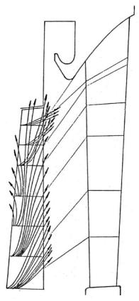
Fig. 2–40. Water motion on the pressure surface of the last stage nozzle vane
Source : M. J. Moore74
www.EngineeringBooksPdf.com
The Thermal Process in Wet-steam Turbines 91
Fig. 2–41. Theoretical characteristic water flow field for LP rotating blades
Source : I. I. Kirillov and R. M.Yablonik75
Now it is beyond question that energy losses due to wetness are unavoidable. However, the amount of these losses in modern turbines is decidedly too high and could be significantly decreased. On the other hand, experimental research in the last few years has not radically changed the understanding of steam and moisture flow in wet-steam turbines and discovered new ways to decline these losses generally. New methods of decreasing energy losses due to wetness have been slow in being developed.The accumulation of new knowledge has resulted in gradual improvements to measurements of the steam path and methods for drying the steam.These methods actually increase the working fluid losses with the removed water, but make the steam flow more efficient.
www.EngineeringBooksPdf.com

The Thermal Process in Wet-steam Turbines 93
References
1McCloskey, T. H., R. B. Dooley, and W. P. McNaughton. 1999. Turbine Steam Path Damage: Theory and Practice, Vols. 1–2. Palo Alto, Calif.: EPRI, 1999.
2Lindinger, R. J. and R. M. Currant. 1981. Corrosion experience in large steam turbines. Power Engineering 85 (10): 76–80.
3Povarov, O. A., G. V. Tomarov, and V. N. Zharov. 1990. Erosion-corrosion of saturated-steam turbine plant elements. Thermal Engineering 37(12):643–647.
4Leyzerovich, A. 1997. Large Power Steam Turbines: Design & Operation, Vols. 1–2. Tulsa, Okla.: PennWell Publishing, 1997.
5Bannister, R. L. and G. J. Silvestri, Jr. 1989. The evolution of central station steam turbines. Mechanical Engineering 111 (2): 70–78.
6Leyzerovich, A. 2000. New benchmarks for steam turbine efficiency. Power Engineering 106 (8): 37–42.
7Sakai, K., S. Morita, T. Yamamoto, and T. Tsunura. 1998. Design and operating experience of the latest 1,000 -MW coal-fired boiler. Hitachi Review 47 (5): 183–187.
8Is 700+°C steam temperature economically viable? Modern Power Systems 18(5): 73–77.
9 Troyanovskii, B. M. 1978. Turbines for Nuclear Power Plants, 2d ed.
(in Russian). Moscow. Energiya, 1978.
10Mounfield, P. R. 1991. World Nuclear Power. London: Routledge, 1991.
11Troyanovskii, Turbines for Nuclear Power Plants
12 Ibid.
13Coit, R. L. 1975. Design trends use utility feed-water heaters and condensers. Combustion 46(8): 14–27.
14Arkad’ev, B. A. 1986. Operating Conditions of Steam Turbosets for Nuclear Power Plants (in Russian). Moscow: Energoatomizdat, 1986.
15 Coit, Design trends, 14–27.
16Zorin, V. M., and V. D. Baibakov. 2003. The optimization of the splitting pressure in the turbines for nuclear power plants. Thermal Engineering 50 (10): 844–851.
17 Baily, F. G., J. A. Booth, K. C. Cotton, and E. H. Miller. 1973. Predicting the Performance of 1800 - rpm Large Steam TurbineGenerators Operating with Light-Water Power Reactors. New York: General Electric, 1973.
18 El-Wakil, M. M. 1984. Powerplant Technology. New York: McGraw-Hill, 1984.
19Deich, M. E., and G. A. Filippov. 1987. Two -Phase Flows in Elements of Thermal Power Equipment (in Russian). Moscow: Energoatomizdat, 1987.
www.EngineeringBooksPdf.com

94 Wet-Steam Turbines for Nuclear Power Plants
20 Moore, M. J. 1976. Gas dynamics of wet steam and energy losses in wet-steam turbines. In Two -Phase Steam Flow in Turbines and Separators: Theory,
Instrumentation, Engineering, ed. M. J. Moore and C.H. Sieverding, 59–126. Washington, D.C.: Hemisphere Publishing Corp., 1976.
21Stodola, A. 1945. Steam and Gas Turbines, Vols. 1–2. trans. L. C. Loewenstein. New York: Peter Smith, 1945.
22Troyanovskii, B. M., G. A. Filippov, and A. E. Bulkin. 1985. Steam and Gas Turbines for Nuclear Power Plants (in Russian). Moscow: Energoatomizdat, 1985.
23Shcheglyaev, A. V. 1993. Steam Turbines, 6th ed., Vols. 1–2 (in Russian). ed. B. M. Troyanovskii. Moscow: Energoatomizdat, 1993.
24Guha, A. 1995. Application of the nonequilibrium theory to steam turbines. In Two -Phase Flows with Phase Transition, 73–110. Rhode Saint Genése, Belgium: Institute for Fluid Dynamics, 1995.
25 Shcheglyaev, Steam Turbines
26Ibid.
27Troyanovskii, Steam and Gas Turbines for Nuclear Power Plants
28Shcheglyaev, Steam Turbines
29Ibid.
30Troyanovskii, Turbines for Nuclear Power Plants
31Troyanovskii, Steam and Gas Turbines for Nuclear Power Plants
32Ibid.
33Ibid.
34Ibid.
35 Ibid.
36 Ibid.
37 Shcheglyaev, Steam Turbines
38 Troyanovskii, Steam and Gas Turbines for Nuclear Power Plants
39 Troyanovskii, Turbines for Nuclear Power Plants
40Troyanovskii, Steam and Gas Turbines for Nuclear Power Plants
41Moore, Gas dynamics. 59–126.
42Baumann, K. 1921. Some recent developments in large steam turbine practice. Engineer 111: 435–458.
43.Moore, Gas dynamics. 59–126
44 Troyanovskii, Steam and Gas Turbines for Nuclear Power Plants
www.EngineeringBooksPdf.com