

литература / Функциональные схемы автоматизации / ANSI_ISA 5.1 2009 - Instrumentation Symbols and Identification
.pdf//^:^^#^~^^"#@::"~^$:~@""#:$@^"*^~@~$"~~""^^:@^^:#^~~\\
- 81 - |
ANSI/ISA-5.1-2009 |
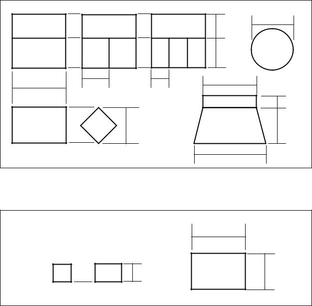
Table 6.4 — Dimensions for Tables 5.4.1, 5.4.2, 5.4.3, and 5.4.4
Note: Numbers in parentheses refer to explanatory notes in Clause 6.3.4.
(1) |
2 |
1.5 |
2 |
1 |
|
|
|
|
2 |
1.5 |
|
|
2R |
1.5R |
|
3 |
2 |
|
|
|
|
|
|
|
|
|
||
|
|
|
|
|
|
|
|
|
|
|
|
|
2 |
1 |
|
3 |
4 |
4 |
|
4 |
|
|
2 |
|
|
|
|
|
||||
1 |
|
|
|
|
|
|
||||
|
|
|
|
|
|
|
|
|
||
|
|
|
|
|
|
|
|
|
|
2 |
|
|
|
|
|
|
0.5 |
|
|
|
|
|
|
1 |
3 |
|
4 |
|
3 |
|
|
|
|
3 |
|
3 |
|
2 |
|
|
0.5 |
||
|
|
|
|
|
|
|
||||
|
|
|
|
|
|
|
|
|
||
|
|
1 |
|
|
2 |
1.5 |
|
|
|
3 |
|
|
|
|
|
4.5 |
|
5 |
|||
5 |
|
|
|
|
|
|
||||
|
|
|
|
|
|
|
|
|||
|
|
|
|
|
|
|
|
|
|
|
|
|
2 |
|
|
|
4 |
2 |
|
|
1 |
|
|
|
|
|
|
|
|
|||
|
|
|
|
|
|
|
|
|
|
3 |
|
3 |
|
|
2.5 |
4 |
|
1 |
|
|
|
|
4.5 |
|
|
|
3.5 |
|
1 |
|||
|
|
|
|
|
|
2 |
||||
|
|
|
|
|
|
|
|
|
|
1 |
|
|
|
|
|
|
|
|
|
2.8 |
|
|
3.5 |
|
|
1 |
1 |
|
|
|
|
|
|
|
|
|
|
|
|
|
|
|
|
6 |
|
3 |
|
|
|
|
|
|
|
|
|
|
|
|
|
|
|
|
|
|
|
1.5 |
|
4. |
|
|
3. |
3.5 |
3.5 |
|
3.5 |
|
|
|
|
|
|
|
|
||||
|
|
|
|
|
|
|
|||
|
|
3. |
|
|
|
|
|
1 |
|
|
|
|
|
|
|
|
0.5 |
|
|
0.75 |
0.5 |
|
4 |
1 |
|
|
|
|
|
0.5 |
1 |
2 |
|
|
M |
4 |
3 |
4 |
|
|
|
|
|
|
|
||||
5 |
|
|
|
|
|
|
|||
|
1 |
|
|
4 |
|
|
|
|
|
|
|
P |
2 |
|
|
0.75 |
|
|
|
|
|
|
|
|
|
|
|||
|
|
|
|
|
|
|
|
|
|
1 |
|
|
|
|
|
|
|
|
|
--`,,```,,,,````-`-`,,`,,`,`,,`---
Copyright International Society of Automation |
|
Provided by IHS under license with ISA |
|
No reproduction or networking permitted without license from IHS |
Not for Resale |
ANSI/ISA-5.1-2009 |
- 82 - |
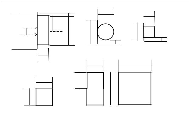
Table 6.5 — Dimensions for Table 5.5
Note: Numbers in parentheses refer to explanatory notes in Clause 6.3.5.
(1) (2)
|
|
|
7 |
|
|
|
4 |
|
|
|
5 |
9 |
4.5 |
3 |
9 |
|
|||
|
|
|
1 |
|
6 |
|
6 |
12
Table 6.6 — Dimensions for Table 5.6
Note: Numbers in parentheses refer to explanatory notes in Clause 6.3.6.
(1) (2)
9
1 |
|
|
|
4.5 |
|
|
|
|
|
|
|
|
|
|
3 |
6 |
|
--`,,```,,,,````-`-`,,`,,`,`,,`---
Copyright International Society of Automation |
|
Provided by IHS under license with ISA |
|
No reproduction or networking permitted without license from IHS |
Not for Resale |
//^:^^#
- 83 - |
ANSI/ISA-5.1-2009 |
|
|
|
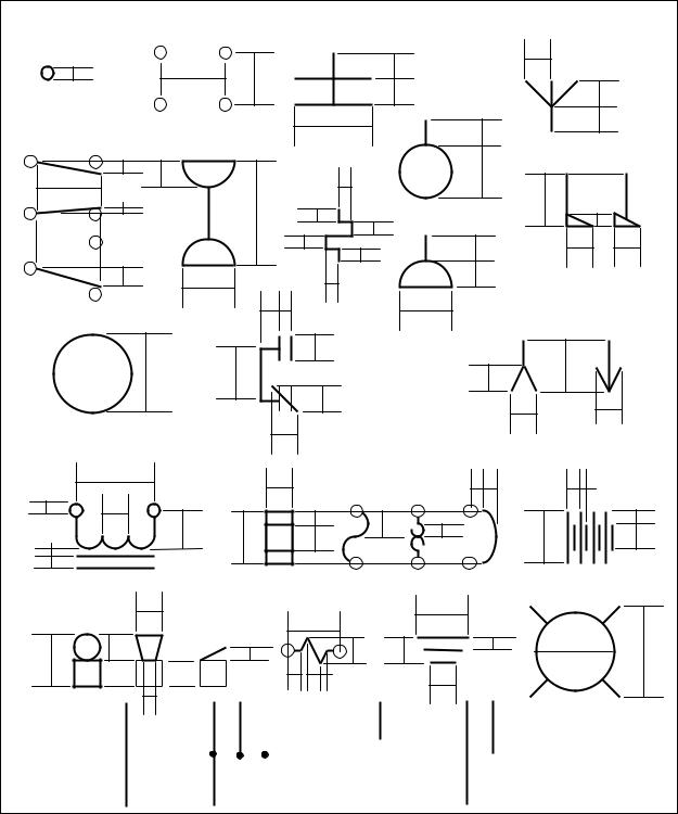
Table 6.7 — Dimensions for Table 5.7 |
|
||||
Note: Numbers in parentheses refer to explanatory notes in Clause 6.3.7. |
|
|
|
|||||
|
|
|
|
1 |
4.5 |
|
|
3 |
|
|
|
|
|
|
|
||
|
|
|
4 |
(4) |
|
(1c) |
|
|
10 |
2 |
(3) |
|
8 |
6.5 |
5 |
|
|
|
|
|
|
(1b) |
(2) |
|
|
|
(1a) |
|
|
|
|
|
|
1 |
|
|
|
|
|
(2) |
1 |
|
||
(2) |
|
|
|
|
|
|
||
|
|
|
|
|
|
|
|
|
|
|
(4) |
3 |
|
|
|
|
|
|
|
|
|
|
|
9 |
--- |
|
|
|
|
|
|
|
|
||
|
|
|
4.5 |
|
4.5 |
|
`,,`,,`,`,,`-`-`,,```,,,,```` |
|
|
|
|
|
|
4.5 |
|
|
|
|
|
|
|
|
|
9 |
|
-- |
|
|
|
|
|
|
|
|
|
|
|
4.5 |
|
|
|
|
|
|
Copyright International Society of Automation |
|
Provided by IHS under license with ISA |
|
No reproduction or networking permitted without license from IHS |
Not for Resale |
//^:^^#^~^^"#@::"~^$:~@""#:$@^"*^~@~$"~~""^^:@^^:#^~~\\
ANSI/ISA-5.1-2009 |
- 84 - |
Table 6.8 — Dimensions for Table 5.8
Note: Numbers in parentheses refer to explanatory notes in Clause 6.3.8.
(1)
|
|
|
|
|
|
|
|
2 |
|
2 |
|
|
1 |
|
5 |
|
4 |
|
|
|
|
|
|
|
|
|
|
|
2 |
|
|
|
|||
|
|
|
|
|
|
|
|
|
|
2 |
|
|
|
|
|
|
|
|
|
|
2 |
|
2 |
|
|
|
|
|
|
|
6 |
|
|
|
|
|
|
|
|
|
|
|
|
|
|
|
|
|
1 |
2 |
|
|
|
|
|
1 |
4 |
|
|
|
5 |
|
|
|
|
|
|
|
|
|
|
|
0.5 |
|
|
|
|
|
|
|
|
4 |
|
|
|
|
|
|
8 |
|
|
|
|
|
|
|
|
|
|
|
|
1 |
|
|
|
1 |
|
|
|
|
|
|
|
|
1 |
|
|
||
|
|
|
|
|
|
|
|
|
|
||
|
|
|
|
|
|
|
1 |
|
|
|
|
|
|
|
|
|
|
|
1 |
2 |
|
|
|
|
|
|
|
|
|
|
|
2 |
2 |
||
|
|
|
|
|
|
|
|
|
|||
|
|
|
|
|
|
|
|
|
2 |
||
|
1.5 |
|
|
|
|
|
|
|
|
|
|
|
|
|
|
4 |
1.5 |
1 |
1 |
|
|
|
|
|
|
|
|
|
|
|
|
|
|||
|
|
|
|
|
|
|
|
|
|
||
|
|
|
|
|
|
|
|
|
4 |
|
|
|
|
|
|
|
|
|
2 |
|
|
|
|
|
|
6 |
|
4 |
|
|
|
|
2 |
4 |
|
|
|
|
|
|
|
|
|
|
|||
|
|
|
|
|
|
|
|
|
|
|
|
|
|
|
|
|
|
|
2 |
|
|
|
|
|
|
|
|
|
|
|
|
|
|
2 |
2 |
|
|
|
|
|
|
|
|
|
|
|
|
|
|
|
|
|
|
2 |
|
|
|
|
|
|
6 |
|
|
|
|
2 |
|
|
1 1 |
1 |
0.5 |
|
|
|
|
|
|
|
|
||||
|
|
|
|
|
|
|
|
|
|
|
|
1 |
2 |
|
|
|
|
|
1 |
|
|
|
1 |
0.5 |
|
|
3 |
|
|
|
2 |
1 |
|
||
|
|
4 |
|
|
2 |
4 |
2 |
||||
|
|
|
|
|
|||||||
|
|
|
|
|
|
|
|||||
1 |
|
|
|
|
|
|
|
|
|
|
|
|
|
2 |
|
|
4 |
|
|
|
|
|
4 |
|
|
|
|
|
2 |
1 |
2 |
2 |
1 |
6 |
7 |
4 |
|
|
|||||
|
|
|
|
|
|
||
|
|
0.5 |
|
|
|
|
|
|
|
1 |
|
|
|
|
|
|
|
1 |
|
2 |
|
|
|
|
|
1 |
|
|
|
|
|
|
|
|
|
|
|
|
2 |
|
|
|
|
|
|
|
|
|
|
2 |
|
|
|
|
|
(1) |
|
|
|
0.5 |
|
|
|
|
|
(1) |
(1) |
|
|
|
|
|
|
|
|
|
|
|
|
|
|
|
||||
|
|
|
|
|
|
|
1 |
|
|
|
|||||
|
|
(1) |
|
|
|
|
|
|
|
|
|
|
|
(1) |
|
|
|
|
|
|
|
|
|
|
|
|
|
|
2 |
|
|
|
|
2 |
|
|
|
|
|
|
|
|
|
|
|
|
|
|
|
|
|
|
|
|
|
|
|
|
|
|
|
|
|
|
|
|
|
|
|
|
|
|
|
|
|
|
|
|
|
|
|
|
|
|
|
|
|
|
|
|
|
|
|
|
|
--`,,```,,,,````-`-`,,`,,`,`,,`---
Copyright International Society of Automation |
|
Provided by IHS under license with ISA |
|
No reproduction or networking permitted without license from IHS |
Not for Resale |
//^:^^#^~^^"#@::"~^$:~@""#:$@^"*^~@~$"~~""^^:@^^:#^~~\\
- 85 - |
ANSI/ISA-5.1-2009 |
Annex A Identification system guidelines (informative annex)
A.1 Identification system
A.1.1 This informative annex to the standard describes a common and almost universally used Identification System for monitoring and control instrument devices and functions that is logical, unique, and consistent in application with a minimum of exceptions, special uses, or requirements.
A.1.2 An identification system is required to identify instrumentation in text and in sketches and drawings when used with graphic symbols as described in Annex B.
A.1.3 The Identification System provides methods for identifying instrumentation required to monitor, control, and operate a processing plant, unit operation, boiler, machine, or any other system that requires measurement, detection, indication, control, modulation, and/or switching of variables or states.
A.1.4 The methods shown are based on the most common ones now in use in the chemical and refining process industries.
A.1.5 Any different methods in use in these industries should be:
a)Revised to conform to this annex.
b)Submitted to ISA (email to standards@isa.org) to determine if they are to be:
1)Included in the next revision of this standard.
A.1.6 ISA should be advised of differences that are normal practice in other industries so that these methods can be incorporated into the next revision of this standard.
A.1.7 A multi-component monitor or control loop consists of some or all of the following (as indicated):
a)Measurement or detection of process variable or state (monitor and control):
1)Measurement element, such as an orifice plate or thermocouple.
2)Measurement transmitter or indicator:
a)With an integral-measuring element, such as a pressure-actuated transmitter or gauge.
b)With a non-integral-measuring element, such as a thermocoupleactuated temperature transmitter or gauge.
b)Conditioning of measurement or input signal (monitor and control):
1)Calculating devices.
2)Calculating functions.
c)Monitoring of process variable (monitor):
1)Indicating or recording device.
Copyright International Society of Automation |
|
Provided by IHS under license with ISA |
|
No reproduction or networking permitted without license from IHS |
Not for Resale |
--`,,```,,,,````-`-`,,`,,`,`,,`---
//^:^^#^~^^"#@::"~^$:~@""#:$@^"*^~@~$"~~""^^:@^^:#^~~\\
//^:^^#^~^^"#@::"~^$:~@""#:$@^"*^~@~$"~~""^^:@^^:#^~~\\
---`,,`,,`,`,,`-`-`,,```,,,,````--
ANSI/ISA-5.1-2009 |
- 86 - |
2)Application software display function.
d)Controlling of process variable (control):
1)Indicating or recording control device.
2)Application software control function.
e)Conditioning of controller or output signal (control):
1)Calculating devices.
2)Calculating functions.
f)Modulation of controlled variable (control):
1)Control valve modulation or on-off action.
2)Resetting another control loop setpoint.
3)Limiting another control loop output signal.
A.1.8 A loop number is assigned to each group of components required to perform the desired function of the monitor or control scheme.
A.1.9 A single component monitor or control loop consists of some or all of the following:
a)Self-acting measuring and control devices, such as pressure or temperature control valves.
b)Self-acting measuring and control devices, such as pressure or temperature safety valves.
c)Single point monitoring devices, such as pressure or temperature gauges.
A.1.10 Each single component may be assigned:
a)A unique loop number, indexed with the plant instrumentation.
b)An instrument tag number, indexed separate from the primary plant instrumentation.
c)A coded type number.
A.2 Instrument index
A.2.1 Loop Identification Numbers and Instrument Identification/Tag Numbers are recorded in an Instrument Index that should be maintained for the life of the facility for the recording and control of all documents and records pertaining to the loops and their instrumentation and functions.
A.2.2 An Instrument Index should contain references to all instrumentation data required by owner and/or government regulatory agency management of change requirements and contain, as a minimum for each loop:
Copyright International Society of Automation |
|
Provided by IHS under license with ISA |
|
No reproduction or networking permitted without license from IHS |
Not for Resale |
//^:^^#^~^^"#@::"~^$:~@""#:$@^"*^~@~$"~~""^^:@^^:#^~~\\
- 87 - |
ANSI/ISA-5.1-2009 |
a)Loop Identification Number.
b)Service Description.
c)Instrument Identification/Tag Numbers.
d)Piping and Instrumentation Diagram drawing numbers.
e)Instrument Data Sheet numbers.
f)Location Plan drawing numbers.
g)Installation Detail drawing numbers.
-- |
A.3 |
Loop identification and instrument identification/tag numbers |
|
-`-`,,```,,,,```` |
|||
A.3.1 Loop Identification Numbers are unique combinations of letters and numbers that are assigned to |
|||
---`,,`,,`,`,,` |
|||
|
being monitored or controlled. |
||
|
|
each monitoring and control loop in a facility to identify the process or machine variable that is |
|
|
A.3.2 |
Instrument Identification/Tag Numbers are unique combinations of letters and numbers that are |
|
|
|
formed by adding letters to the Loop Identification Number to define the purpose of each loop |
|
|
|
device and/or function that comprises a monitoring or control loop. |
|
|
A.3.3 |
Instrument Identification/Tag Numbers are also called Instrument Identification Number, |
|
|
|
Instrument Tag Number, Instrument Number, or Tag Number. |
|
|
A.3.4 |
Examples of Loop Identification and Instrument Identification/Tag Numbers for a typical loop with |
|
|
|
references to sub-clauses relevant to the components of the Loop and Instrument Identification |
|
|
|
/Tag Numbers are given in Table A.1 — Typical Loop and Instrument Identification/Tag Numbers. |
|
|
A.4 |
Loop identification number |
|
|
A.4.1 |
A Loop Identification Number is a unique combination of letters and numbers that is assigned to |
|
|
|
each monitoring and control loop in a facility to identify the process or machine variable that is |
|
|
|
being monitored or controlled and should be assigned to each: |
|
a)Primary monitoring and control loop.
b)Self-contained measuring or control device.
c)Secondary measuring or monitoring device if future primary loops are anticipated or if it is the standard practice of the User.
A.4.2 Loop Identification Numbers assigned, as the basis for Instrument Identification/Tag Numbers to auxiliary or accessory devices, should be the same as the loop for which the devices are required.
A.4.3 Loop Identification Numbers are assigned:
a)First Letters from Table 4.1 to identify loop Measured/Initiating Variables.
Copyright International Society of Automation |
|
Provided by IHS under license with ISA |
|
No reproduction or networking permitted without license from IHS |
Not for Resale |
ANSI/ISA-5.1-2009 |
- 88 - |
b)Numerals to form a unique loop identity.
c)Optional loop suffixes to identify identical loops on identical pieces of equipment or services.
A.5 Loop identification number letters
A.5.1 Loop Identification Number letters should be selected from Table 4.1 to identify the loop Measured/Initiating Variable according to one of the following methods selected by the end user:
a)Measured/Initiating Variable: only a Measured/Initiating Variable is selected, such as analysis [A], flow [F], level [L], pressure [P], temperature [T], etc.
b)Measured/Initiating Variable with Variable Modifier: a Measured/Initiating Variable and, when applicable, a Variable Modifier is selected, such as analysis [A], flow [F], flow quantity [FQ], level [L], pressure [P], differential pressure [PD], temperature [T], differential temperature [TD], etc.
c)First-Letters: a Measured/Initiating Variable and, when applicable, a Variable Modifier, only if the resulting First-Letter combination defines a loop variable that can be measured directly, such as pressure differential [PD] as opposed to one that is mathematically derived, such as flow ratio [FF].
A.5.2 |
A Measured/Initiating Variable in combination with the safety Variable Modifier [S] is always |
|
|
treated as a loop variable in each of the preceding selection methods to identify self-acting |
|
|
devices intended to protect against emergency conditions that may be hazardous to plant |
|
|
personnel, plant equipment, or the environment. |
|
A.5.3 |
A Measured/Initiating Variable is selected according to the physical or mechanical property that is |
|
|
being measured, derived or initiates an action and not according to the construction or mode of |
|
|
actuation of the measuring device or the property or the action it initiates: |
|
a) |
A loop that controls pressure in a vessel by manipulating gas or vapor flow to or from the |
|
|
vessel is a pressure [P] loop and not a flow [F] loop. |
|
b) |
A loop that measures pressure differential across: |
|
|
1) |
An orifice plate from which flow rate is calculated is a flow [F] loop and not a |
|
|
pressure [P] or pressure differential [PD] loop. |
|
2) |
A fluid interface in a vessel is a level [L] loop and not a pressure [P] or pressure |
-- |
|
differential [PD] loop. |
-`-`,,```,,,,```` |
|
|
3) |
A filter bed or element is a pressure [P] or pressure differential [PD]-loop. |
|
---`,,`,,`,`,,` |
|
|
A.6 |
Loop identification number numerals |
|
A.6.1 Loop Identification Number numerals should be assigned to loop measured variable letters according to one of the following methods selected by the end user:
//^:^^#^~^^"#@::"~^$:~@""#:$@^"*^~@~$"~~""^^:@^^:#^~~\\
Copyright International Society of Automation |
|
Provided by IHS under license with ISA |
|
No reproduction or networking permitted without license from IHS |
Not for Resale |
//^:^^#^~^^"#@::"~^$:~@""#:$@^"*^~@~$"~~""^^:@^^:#^~~\\
- 89 - |
ANSI/ISA-5.1-2009 |
a)Parallel: duplicated numerical sequences for each loop variable letter or first letter combination.
b)Serial: single numerical sequence regardless of loop variable letter or first letter combination.
c)Parallel/Serial: parallel sequences for selected loop variable letters or first letter combinations and a serial sequence for the remainder.
A.6.2 Loop Number numerical sequences are normally three or more digits, -*01, -*001, -*0001, etc. where the asterisk * can be :
a)Any digit from zero to 9.
b)Coded digits related to drawing numbers, unit numbers, equipment numbers, etc.
A.6.3 *00, *000, *0000, etc. should be used only for special, significant, or critical loops as defined by the User.
A.6.4 000, 0000, 00000, etc. should not be used
A.6.5 Loop |
Identification |
letters and numbers should be assigned in accordance with one of the |
|
|
following Loop Numbering Schemes: |
||
a) |
|
No. 1 |
Parallel – Measured/Initiating Variable. |
b) |
|
No. 2 |
Parallel – Measured/Initiating Variable with Variable Modifier. |
c) |
|
No. 3 |
Parallel – First Letter(s). |
d) |
|
No. 4 |
Series – Measured/Initiating Variable. |
e) |
|
No. 5 |
Series – Measured/Initiating Variable with Variable Modifier. |
f) |
|
No. 6 |
Series – First Letter(s). |
g) |
|
No. 7 |
Parallel/Series – Measured/Initiating Variable. |
h) |
|
No. 8 |
Parallel/Series – Measured/Initiating Variable with Variable Modifier. |
i) |
|
No. 9 |
Parallel/Series – First Letter(s). |
A.6.6 Gaps should be left in any sequence to allow for the addition of future loops. |
|||
A.6.7 See |
Table A.2 — |
Allowable letter/number combinations for, loop numbering schemes for |
|
|
examples of typical Loop Number assignments. |
||
A.7 Optional loop number prefixes
A.7.1 Loop Number Prefixes consisting of any combination of alpha/numeric characters that may be added to Loop Numbers to identify loop location, such as a complex, plant, or unit should be located before the Measured/Initiating Variable, for example, a flow loop in processing plant #1 might be [PP1-F*01].
--`,,```,,,,````-`-`,,`,,`,`,,`---
Copyright International Society of Automation |
|
Provided by IHS under license with ISA |
|
No reproduction or networking permitted without license from IHS |
Not for Resale |
ANSI/ISA-5.1-2009 |
- 90 - |
A.7.2 Loop Number Prefixes should:
a)Not necessarily be shown on drawings or indexes but covered by a general note on a legend sheet or a note on each drawing or index sheet.
b)Be shown for all uses on drawings when more than one prefix is required by loops shown on the drawing.
c)Be shown when used in text.
A.8 Instrument identification/tag number
A.8.1 An Instrument Identification/Tag Number is a unique combination of letters and numbers that is assigned to define the purpose of each loop device and/or function that comprises a monitoring or control loop.
A.8.2 Adding a Variable Modifier, if needed, and Succeeding Letters to the Loop Identification Number letters forms an Instrument Identification/Tag Number.
A.8.3 Instrument Identification/Tag Numbers may also be called Instrument Identification Number, Instrument Tag Number, Instrument Number, or Tag Number.
A.9 Function identification letters
A.9.1 Instrument Function Identification letters should be selected from Table 4.1, Identification Letters, and added to the Loop Identification Number letters to form an Instrument Functional Identity.
A.9.2 The sequence of letters in a Functional Identification should be in the same left-to-right order as the columns in Table 4.1:
a)Measured or Initiating Variable, from Column 1.
b)Modifier, if required, from Column 2.
c)Passive Readout Function, from Column 3.
d)Active Output Function, from Column 4.
e)Modifier(s), if required, from Column 5.
A.9.3 Functional Identifications should use one Readout/Passive Function or one Output/Active Function to identify each device or function except, as is common for:
a)Indicating /recording controller/switch instruments or functions in which one Passive Function, indicate [I] or record [R] and one Active Function, control [C] or switch [S], is combined to form, for example, pressure recording controller [PRC], or low-pressure indicating switch [PISL].
b)Self-actuated control valves, in which two Active Functions control [C] and valve [V] are combined to form, for example, pressure control valve [PCV].
|
--`,,```,,,,````-`-`,,`,,`,`,,`--- |
Copyright International Society of Automation |
|
Provided by IHS under license with ISA |
|
No reproduction or networking permitted without license from IHS |
Not for Resale |
//^:^^#^~^^"#@::"~^$:~@""#:$@^"*^~@~$"~~""^^:@^^:#^~~\\