

литература / Функциональные схемы автоматизации / ANSI_ISA 5.1 2009 - Instrumentation Symbols and Identification
.pdf- 31 - |
ANSI/ISA-5.1-2009 |
5 Graphic symbol tables
5.1Graphic symbol tables
5.1.1This clause provides in tabular form the graphic building blocks that are used to construct diagrams for measurement and control loops, instruments, and functions in a concise, easily referenced manner.
5.1.2The graphic symbol sets included in this clause are intended to be used to prepare:
a)Instrumentation diagrams.
b)Functional diagrams.
c)Binary logic diagrams.
d)Electrical schematics.
5.1.3The graphic symbols shown in the tables are drawn full size for use in full size sketches or drawings.
5.1.4The device and function symbols shown in Table 5.1.1 are based on the traditional 7/16-inch or 11mm circle format but may be changed to the often-used 1/2-inch or 12mm circle format.
5.1.5Consideration shall be given to the size of reduced P&IDs when selecting symbol sizing.
5.1.6All symbols shall maintain the size ratios shown in the tables when reduced or increased in size.
5.2Tables to be used for common applications
5.2.1Instrumentation diagrams that represent instrumentation devices and functions shall be constructed from the symbols shown in:
a)Tables 5.1.1 and 5.1.2 — Measurement and control devices or functions.
b)Tables 5.2.1, 5.2.2, 5.2.3, and 5.2.4 — Measurement elements and transmitters.
c)Tables 5.3.1 and 5.3.2 — Lines, instrument to process or instrument to instrument.
d)Tables 5.4.1, 5.4.2, 5.4.3, and 5.4.4 — Final control elements.
e)Table 5.6 — Signal processing function blocks.
5.2.2Functional diagrams that represent monitoring and control loops shall be constructed from the symbols shown in:
a)Table 5.5 — Functional diagramming symbols.
b)Table 5.6 — Signal processing function block symbols.
c)Table 5.7 — Binary logic symbols.
|
--`,,```,,,,````-`-`,,`,,`,`,,`--- |
Copyright International Society of Automation |
|
Provided by IHS under license with ISA |
|
No reproduction or networking permitted without license from IHS |
Not for Resale |
//^:^^#^~^^"#@::"~^$:~@""#:$@^"*^~@~$"~~""^^:@^^:#^~~\\
ANSI/ISA-5.1-2009 |
- 32 - |
5.2.3Binary logic diagrams that represent logic processes shall be constructed from the symbols shown in:
a)Table 5.1.1 — Measurement and control devices or functions.
b)Table 5.7 — Binary logic symbols.
5.2.4Electrical schematics that represent electrical circuits shall be constructed from the symbols shown in:
a)Table 5.1.1 — Measurement and control devices or functions.
b)Table 5.8 — Electrical schematic symbols.
5.2.5Symbols may be developed to show devices and functions not covered by this standard or to simplify the depiction of frequently used instrumentation. Such uses shall be fully detailed by sketches or notes on the drawing legend and detail sheets.
5.2.6If new or revised symbols are developed they should be submitted to the ISA-5.1 committee for inclusion in the next revision of this standard.
5.3Graphic symbol table explanatory notes
The following notes, indicated in Tables 5.1 through 5.8 by parentheses, shall be used as an aid in understanding the meanings of the symbols.
|
5.3.1 |
Tables 5.1.1 and 5.1.2 — Instrumentation device and function symbols: |
|
|
(1) |
Devices and functions that are represented by these bubble symbols are: |
|
|
|
(a) |
Used in shared display, shared control, configurable, microprocessor-based, and data- |
|
|
linked instrumentation where the functions are accessible by the operator via a shared display or |
|
|
|
monitor. |
|
|
|
(b) |
Configured in control systems that include, but are not limited to, distributed control |
|
|
systems (DCS), programmable logic controllers (PLC), personal computers (PC), and intelligent |
|
|
|
transmitters and valve positioners. |
|
|
(2) |
The user shall select and document one of the following for use of these symbols in a: |
|
|
|
(a) |
Primary shared-display, shared-control system. |
|
|
(b) |
Basic Process Control System (BPCS). |
//^:^^#^~^^"#@::"~^$:~@""#:$@^"*^~@~$"~~""^^:@^^:#^~~\\ |
(3) |
The user shall select and document one of the following for use of these symbols in an: |
|
|
(a) |
Alternate shared-display, shared-control system. |
|
|
|
||
|
|
(b) |
Safety Instrumented System (SIS). |
|
(4) |
Devices and functions represented by these bubble symbols are configured in computer systems |
|
|
that include, but are not limited to: |
||
--`,,```,,,,````-`-`,,`,,`,`,,`---
Copyright International Society of Automation |
|
Provided by IHS under license with ISA |
|
No reproduction or networking permitted without license from IHS |
Not for Resale |
|
|
|
- 33 - |
ANSI/ISA-5.1-2009 |
|
|
(a) |
Process controllers, process optimizers, statistical process control, model-predictive |
|
|
|
process control, analyzer controllers, business computers, manufacturing execution systems, and |
||
|
|
other systems that interact with the process by manipulating setpoints in the BPCS. |
||
|
|
(b) |
High Level Control System (HLCS) |
|
|
(5) |
Discrete devices or functions that are hardware-based and are either stand-alone or are |
||
|
connected to other instruments, devices, or systems that include, but are not limited to, transmitters, |
|||
//^:^^#^~^^"#@::"~^$:~@""#:$@^"*^~@~$"~~""^^:@^^:#^~~\\ |
switches, relays, controllers, and control valves. |
|
||
(6) |
(b) |
These symbols are not recommended for depicting complex DCS, PLC, or SIS |
||
|
Accessibility includes viewing, setpoint adjustment, operating mode changing, and any other |
|||
|
operator actions required to operate the instrumentation. |
|
||
|
(7) |
Functions represented by these symbols are used for simple interlock logic: |
|
|
|
|
(a) |
A description of the logic should be shown nearby or in the notes section of the drawing |
|
|
|
or sketch if the intended logic is not clearly understandable. |
|
|
|
|
applications that require other than ‘AND’ and ‘OR’ signal gates. |
|
|
|
(8) |
A logic number, letter, or number/letter combination identification shall be used if more than one |
||
|
logic scheme is used on the project by: |
|
||
|
|
(a) |
Replacing [I], [A], and [O] with the logic identification. |
|
|
|
(b) |
Appending the logic identification outside the symbol. |
|
|
5.3.2 |
Tables 5.2.1, 5.2.2, 5.2.3, 5.2.4, and 5.2.5 — Measurement symbols |
|
|
(1)Measurements are depicted by:
(a)Bubbles only.
(b)Bubbles and graphics.
(2)These symbols shall be used for process or equipment measurements if:
(a)A graphic symbol does not exist.
(b)The user does not use graphic symbols.
(3)Transmitter [T] may be controller [C], indicator [I], recorder [R], or switch [S].
(4)User engineering and design standards, practices, and/or guidelines shall document which choices are selected.
5.3.3Tables 5.3.1 and 5.3.2 — Line symbols:
(1)Power supplies shall be shown when:
(a)Different from those normally used, e.g., 120 Vdc when normal is 24 Vdc.
(b)When a device requires an independent power supply.
--`,,```,,,,````-`-`,,`,,`,`,,`---
Copyright International Society of Automation |
|
Provided by IHS under license with ISA |
|
No reproduction or networking permitted without license from IHS |
Not for Resale |
//^:^^#^~^^"#@::"~^$:~@""#:$@^"*^~@~$"~~""^^:@^^:#^~~\\
ANSI/ISA-5.1-2009 |
- 34 - |
(c)Affected by controller or switch actions.
(2)Arrows shall be used if needed to clarify direction of signal flow.
(3)Users engineering and design standards, practices and/or guidelines shall document which symbol has been selected.
(4)The line symbols connect devices and functions that are integral parts of dedicated systems, such as distributed control systems (DCS), programmable logic controllers (PLC), personal computer systems (PC), and computer control systems (CCS) over a dedicated communication link.
(5)The line symbols connect independent microprocessor-based and computer-based systems to each other over a dedicated communications link, using but not limited to the RS232 protocol.
(6)The line symbols connect “intelligent” devices, such as microprocessor-based transmitters and control valve positioners that contain control functionality, to other such devices and to the instrumentation system, using but not limited to Ethernet fieldbus protocols.
(7)The line symbols connect “smart” devices, such as transmitters, to instrumentation system input signal terminals and provide a superimposed digital signal that is used for instrument diagnostics and calibration.
5.3.4Tables 5.4.1, 5.4.2, 5.4.3 and 5.4.4 — Final control element symbols:
(1)Users engineering and design standards, practices, and/or guidelines shall document which symbols have been selected.
(2)Element symbols 1 through 14, when combined with actuator symbols 1 through 16, represent process control valves.
(3)Element symbol 2, when combined with actuator symbols 20 and 21, represent pressure safety
valves.
(4)Element symbols 15 through 19, when combined with actuator symbols 13, 14, and 15, represent on-off solenoid valves.
(5)Element symbol 21, when combined with actuator symbols 1 through 16, represents a variable speed control unit.
(6)Element symbol 21 represents a motor that manipulates or controls a process variable.
(7)Actuator symbols 1 through 16, when combined with element symbols 1 through 14, represent process control valves and with element symbol 21 represents a variable speed control unit.
(8)Actuator symbols 17, 18, and 19, when combined with element symbols 15 through 19, represent on-off solenoid valves.
(9)Actuator symbols 20 and 21, when combined with element symbol 2, represent pressure safety
valves.
(10)The symbols are applicable to all types of control valves and actuators.
5.3.5Table 5.5 — Functional diagramming symbols:
(1)Signal flow is assumed to be from top-to-bottom or from left-to-right.
--`,,```,,,,````-`-`,,`,,`,`,,`---
Copyright International Society of Automation |
|
Provided by IHS under license with ISA |
|
No reproduction or networking permitted without license from IHS |
Not for Resale |
- 35 - |
ANSI/ISA-5.1-2009 |
(2)Symbols are shown in a vertical diagram format.
(3)Symbols shall be rotated 90 degrees counterclockwise in a horizontal diagram format.
(4)Insert signal processing symbol from Table 5.6 at (*).
5.3.6Table 5.6 — Signal processing function block symbols:
(1)Symbols in small squares and rectangles are as used with symbol #1 from Table 5.1.2.
(2)Symbols in large rectangles are as used with symbol #5 from Table 5.5.
(3)Users engineering and design standards, practices and/or guidelines shall document which symbol has been selected.
5.3.7Table 5.7 — Binary logic symbols:
(1)True signals are equal to binary one, and false signals are equal to binary zero.
(2)Alternate symbols shall be used only for “AND’ and “OR” gates.
(3)Users engineering and design standards, practices and/or guidelines shall document which symbol has been selected.
5.3.8Table 5 8 — Electrical schematic symbols
(1)All devices are shown in the unactuated or de-energized condition.
(2)Switch contacts 2, 3, and 4 shall be actuated by:
(a)Hand.
(b)Actuator symbols 5 and 6.
(3)Actuator symbols 5 and 6 shall actuate switch symbols 2, 3, and 4.
(4)Switch symbols 7, 8, and 9.shall be actuated by:
(a)Hand.
(b)Actuator symbols 11 through 16.
(c)Bubble symbol for device or function assigned to actuate the switch symbol.
(5)Actuator symbols 11 through 16 shall actuate switch symbols 7, 8, and 9.
(6)Users engineering and design standards, practices and/or guidelines shall document which symbol has been selected.
-- |
//^:^^#^~^^"#@::"~^$:~@""#:$@^"*^~@~$"~~""^^:@^^:#^~~\\ |
`-`-`,,```,,,,```` |
|
Copyright International Society of Automation |
|
Provided by IHS under license with ISA |
|
No reproduction or networking permitted without license from IHS |
Not for Resale |
ANSI/ISA-5.1-2009 |
- 36 - |
|
|
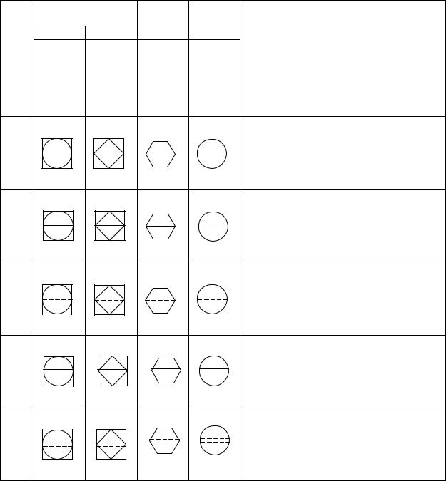
Table 5.1.1 — Instrumentation device and function symbols |
||||
|
Note: Numbers in parentheses refer to explanatory notes in Clause 5.3.1. |
|
||||
|
|
Shared display, |
|
|
|
|
|
|
Shared control (1) |
C |
D |
|
|
|
|
A |
B |
|
|
|
|
|
Primary |
Alternate |
|
|
|
|
No. |
Choice |
Computer |
|
Location & accessibility (6) |
|
|
Choice |
|
||||
|
|
or |
|
|
||
|
|
or |
Systems |
Discrete |
|
|
|
|
Basic |
|
|||
|
|
Safety |
and |
|
||
|
|
Process |
(5) |
|
||
|
|
Instrumented |
Software |
|
||
|
|
Control |
|
|
||
|
|
System |
(4) |
|
|
|
|
|
System |
|
|
||
|
|
(3) |
|
|
|
|
|
|
(2) |
|
|
|
|
|
|
|
|
|
|
|
|
|
|
|
|
• |
Located in field. |
|
1 |
|
|
|
• |
Not panel, cabinet, or console mounted. |
|
|
|
|
|
• |
Visible at field location. |
|
|
|
|
|
• |
Normally operator accessible. |
|
|
|
|
|
• |
Located in or on front of central or main panel or |
|
2 |
|
|
|
|
console. |
|
|
|
|
|
• |
Visible on front of panel or on video display. |
|
|
|
|
|
• |
Normally operator accessible at panel front or console. |
|
|
|
|
|
• |
Located in rear of central or main panel. |
|
3 |
|
|
|
• |
Located in cabinet behind panel. |
|
|
|
|
|
• |
Not visible on front of panel or on video display. |
|
|
|
|
|
• |
Not normally operator accessible at panel or console. |
-`,,```,,,,````-- |
|
|
|
|
• |
Located in or on front of secondary or local panel or |
-` |
4 |
|
|
|
|
console. |
`,,`,,`,`,,` |
|
|
|
|
||
|
|
|
|
• |
Visible on front of panel or on video display. |
|
|
|
|
|
|
||
--- |
|
|
|
|
• |
Normally operator accessible at panel front or console. |
|
|
|
|
|
|
|
|
|
|
|
|
• |
Located in rear of secondary or local panel. |
|
5 |
|
|
|
• |
Located in field cabinet. |
|
|
|
|
|
• |
Not visible on front of panel or on video display. |
|
|
|
|
|
• |
Not normally operator accessible at panel or console. |
Copyright International Society of Automation |
|
Provided by IHS under license with ISA |
|
No reproduction or networking permitted without license from IHS |
Not for Resale |
//^:^^#^~^^"#@::"~^$:~@""#:$@^"*^~@~$"~~""^^:@^^:#^~~\\
- 37 - |
ANSI/ISA-5.1-2009 |
Table 5.1.2 — Instrumentation device or function symbols, miscellaneous
Note: Numbers in parentheses refer to explanatory notes in Clause 5.3.1.
No |
|
Symbol |
|
Description |
||||
|
|
|
|
|
|
|
|
|
|
|
|
|
|
|
|
• |
Signal processing function: |
1 |
|
|
|
|
|
|
• |
Locate in upper right or left quadrant of symbols above. |
|
|
|
|
|
|
|
• |
Attach to symbols above where affected signals are connected. |
|
|
|
|
|
|
|
• |
Insert signal processing symbol from Table 5.6 |
|
|
|
|
|
|
|
• |
Expand symbol by 50% increments for larger function symbols. |
|
|
|
|
|
|
|
|
|
|
|
|
|
|
|
|
• |
Panel-mounted patchboard plug-in point. |
2 |
|
|
|
C |
|
• |
Console matrix point. |
|
|
|
|
|
• |
C-12 equals patchboard column and row respectively, as an example. |
|||
|
|
12 |
|
|
||||
|
|
|
|
|
|
|||
|
|
|
|
|
|
|
|
|
|
(7) (8) |
|
|
|
|
|
• |
Generic interlock logic function. |
3 |
|
|
|
I |
• |
Undefined interlock logic function. |
||
|
|
|
|
|
|
|||
|
|
|
|
|
|
|
|
|
4 |
(7) (8) |
|
|
|
|
|
• |
‘AND’ interlock logic function. |
|
|
|
I |
|
|
|||
|
|
|
|
|
|
|||
|
|
|
|
|
|
|
|
|
5 |
(7) (8) |
|
|
|
|
|
• |
‘OR’ interlock logic function. |
|
|
|
I |
|
|
|||
|
|
|
|
|
|
|||
|
|
|
|
|
|
|
|
|
|
|
|
|
|
|
|
• |
Instruments or functions sharing a common housing. |
6 |
|
|
|
|
|
|
• |
It is not mandatory to show a common housing. |
|
|
|
|
|
|
|
• |
Notes shall be used to identify instruments in common housings not using this |
|
|
|
|
|
|
|
|
symbol. |
|
|
|
|
|
|
|
|
|
|
|
|
|
|
|
|
• |
Pilot light. |
7 |
|
|
|
|
|
|
• |
Circle shall be replaced with any symbol from column D in Table 5.1.1 if location and |
|
|
|
|
|
|
|
|
accessibility needs to be shown. |
|
|
|
|
|
|
|
|
|
|
--`,,```,,,,````-`-`,,`,,`,`,,`--- |
Copyright International Society of Automation |
|
Provided by IHS under license with ISA |
|
No reproduction or networking permitted without license from IHS |
Not for Resale |
//^:^^#^~^^"#@::"~^$:~@""#:$@^"*^~@~$"~~""^^:@^^:#^~~\\
ANSI/ISA-5.1-2009 |
- 38 - |
Table 5.2.1 — Measurement symbols: primary elements and transmitters
Note: Numbers in parentheses refer to explanatory notes in Clause 5.3.2.
No |
Symbol |
|
Description |
|
|
|
|
|
(1a) (2) |
• |
Generic primary element, bubble format. |
1 |
|
• |
Notation (*) from Table 5.2.2 should be used to identify type of element. |
|
?E |
• |
Connect to process or other instruments by symbols from Tables 5.3.1 and 5.3.2. |
|
• |
Insert in or on process flow line, vessel, or equipment. |
|
|
(*) |
|
|
|
|
|
|
|
(1a) ( (2) (3) |
• |
Transmitter with integral primary element, bubble format. |
2 |
?T |
• |
Notation (*) from Table 5.2.2 should be used to identify type of element. |
|
• |
Connect to process or other instruments by symbols from Tables 5.3.1 and 5.3.2. |
|
|
|
||
|
(*) |
• |
Insert in or on process flow line, vessel, or equipment. |
|
|
|
|
|
(1a) (2) (3) |
• |
Transmitter with close coupled primary element, bubble format |
3 |
?T |
• |
Notation (*) from Table 5.2.2 should be used to identify type of element. |
|
|
• |
Connecting line shall be equal to or less than 0.25 inches (6 millimeters). |
|
|
• |
Connect to process or other instruments by symbols from Tables 5.3.1 and 5.3.2. |
|
|
• |
Insert element in or on process flow line, vessel, or equipment. |
|
?E |
|
|
|
(*) |
|
|
|
|
|
|
(1a) (3) |
?T |
• |
Transmitter with remote primary element, bubble format. |
4 |
• |
Notation (*) from Table 5.2.2 should be used to identify type of element. |
•Connecting line shall be equal to or greater than 0.5 inches (12 millimeters).
|
|
?E |
|
|
|
|
• |
Connect to process or other instruments by symbols from Tables 5.3.1 and 5.3.2. |
|
|
|
|
|
|
|
• |
Insert element in or on process flow line, vessel, or equipment. |
||
|
|
|
|
|
|
|
|
||
|
|
|
|
(*) |
|
|
|
|
|
|
|
|
|
|
|
|
|
|
|
(1b) (3) |
|
|
|
|
• |
Transmitter with integral primary element inserted in or on process flow line, vessel, |
|||
5 |
|
|
|
|
?T |
|
|
or equipment, bubble/graphic format. |
|
|
|
|
|
|
|
|
|
• |
Insert primary element symbol from Table 5.2.3 at #. |
|
|
|
|
|
|
|
|
• |
Connect to other instruments by symbols from Table 5.3.2. |
|
|
|
|
|
# |
|
|
|
|
|
|
|
|
|
|
|
|
|
|
|
|
|
|
|
|
|
|
|
|
(1b) (3) |
|
?T |
|
• |
Transmitter with close-coupled primary element inserted in or on process flow line, |
||||
6 |
|
|
|
|
|
|
vessel, or equipment, bubble/graphic format. |
||
|
|
|
|
|
|
|
|
• |
Insert primary element symbol from Table 5.2.3 at #. |
|
|
|
|
|
|
|
|
• |
Connecting line shall be equal to or less than 0.25 inches (6 millimeters). |
|
|
|
|
|
|
|
|
• |
Connect to other instruments by symbols from Table 5.3.2. |
|
|
|
|
|
# |
|
|
|
|
|
|
|
|
|
|
|
|
|
|
|
|
|
|
|
|
|
|
|
|
(1b) (3) |
|
|
|
|
• |
Transmitter with remote primary element inserted in or on process flow line, vessel, |
|||
7 |
|
|
|
|
|
|
?E |
|
or equipment, bubble/graphic format. |
|
|
|
|
|
|
|
• |
Insert primary element symbol from Table 5.2.3 at #. |
|
|
|
|
|
|
|
|
|
• |
Connecting line may be any signal line from Table 5.2.3. |
|
|
|
|
|
|
|
|
• |
Connecting line shall be equal to or greater than 0.5 inches (12 millimeters). |
|
# |
|
|
|
|
|
|||
|
|
|
|
|
|
• |
Connect to other instruments by symbols from Table 5.3.2. |
||
|
|
|
|
|
|
|
|
||
|
|
|
|
|
|
|
|
|
|
--`,,```,,,,````-`-`,,`,,`,`,,`---
//^:^^#^~^^"#@::"~^$:~@""#:$@^"*^~@~$"~~""^^:@^^:#^~~\\
Copyright International Society of Automation |
|
Provided by IHS under license with ISA |
|
No reproduction or networking permitted without license from IHS |
Not for Resale |

- 39 - |
ANSI/ISA-5.1-2009 |
---`,,`,,`,`,,`-`-`,,```,,,,````--
Table 5.2.2 — Measurement symbols: measurement notations (4)
Note: Numbers in parentheses refer to explanatory notes in Clause 5.3.2
Analysis
AIR |
= |
Excess air |
H2O |
= |
Water |
O2 |
= |
Oxygen |
UV |
= |
Ultraviolet |
CO |
= |
Carbon monoxide |
H2S |
= |
Hydrogen sulfide |
OP |
= |
Opacity |
VIS |
= |
Visible light |
CO2 |
= |
Carbon dioxide |
HUM |
= |
Humidity |
ORP |
= |
Oxidation reduction |
VISC |
= |
Viscosity |
COL |
= |
Color |
IR |
= |
Infrared |
pH |
= |
Hydrogen ion |
|
= |
|
COMB |
= |
Combustibles |
LC |
= |
Liquid chromatograph |
REF |
= |
Refractometer |
|
= |
|
COND |
= |
Elec. conductivity |
MOIST |
= |
Moisture |
RI |
= |
Refractive index |
|
= |
|
DEN |
= |
Density |
MS |
= |
Mass spectrometer |
TC |
= |
Thermal conductivity |
|
= |
|
GC |
= |
Gas chromatograph |
NIR |
= |
Near infrared |
TDL |
= |
Tunable diode laser |
|
= |
|
|
|
|
|
|
Flow |
|
|
|
|
|
|
CFR |
= |
Constant flow regulator |
OP |
= |
Orifice plate |
PT |
= |
Pitot tube |
VENT |
= |
Venturi tube |
CONE |
= |
Cone |
OP-CT |
= |
Corner taps |
PV |
= |
Pitot venturi |
VOR |
= |
Vortex Shedding |
COR |
= |
Coriollis |
OP-CQ |
= |
Circle quadrant |
SNR |
= |
Sonar |
WDG |
= |
Wedge |
DOP |
= |
Doppler |
OP-E |
= |
Eccentric |
SON |
|
Sonic |
|
= |
|
DSON |
= |
Doppler sonic |
OP-FT |
= |
Flange taps |
TAR |
= |
Target |
|
|
|
FLN |
= |
Flow nozzle |
OP-MH |
= |
Multi-hole |
THER |
= |
Thermal |
|
= |
|
FLT |
= |
Flow tube |
OP-P |
= |
Pipe taps |
TTS |
= |
Transit time sonic |
|
= |
|
LAM |
= |
Laminar |
OP-VC |
= |
Vena contracta taps |
TUR |
= |
Turbine |
|
= |
|
MAG |
= |
Magnetic |
PD |
= |
Positive displacement |
US |
= |
Ultrasonic |
|
= |
|
|
|
|
|
|
Level |
|
|
|
|
|
|
CAP |
= Capacitance |
GWR |
= Guided wave radar |
NUC |
= Nuclear |
US |
= Ultrasonic |
||||
d/p |
= |
Differential pressure |
LSR |
= |
Laser |
RAD |
= |
Radar |
|
= |
|
DI |
= |
Dielectric constant |
MAG |
= Magnetic |
RES |
= Resistance |
|
= |
|
||
DP |
= |
Differential pressure |
MS |
= |
Magnetostrictive |
SON |
= |
Sonic |
|
= |
|
|
|
|
|
|
Pressure |
|
|
|
|
|
|
ABS |
= |
Absolute |
MAN |
= |
Manometer |
VAC |
= |
Vacuum |
|
= |
|
AVG |
= |
Average |
P-V |
= |
Pressure-vacuum |
|
|
|
|
|
|
DRF |
= |
Draft |
SG |
= |
Strain gage |
|
= |
|
|
= |
|
|
|
|
|
|
Temperature |
|
|
|
|
|
|
BM |
= |
Bi-metallic |
RTD |
= Resistance temp detector |
TCK |
= Thermocouple type K |
TRAN |
= Transistor |
|||
IR |
= |
Infrared |
TC |
= Thermocouple |
TCT |
= Thermocouple type T |
|
= |
|
||
RAD |
= Radiation |
TCE |
= Thermocouple type E |
THRM |
= Thermistor |
|
= |
|
|||
RP |
= |
Radiation pyrometer |
TCJ |
= Thermocouple type J |
TMP |
= Thermopile |
|
= |
|
||
|
|
|
|
|
Miscellaneous |
|
|
|
|
Radiation |
|
|
Burner, Combustion |
|
|
Position |
|
|
Quantity |
|
|
||
FR |
= |
Flame rod |
CAP |
= |
Capacitance |
PE |
= |
Photoelectric |
α |
= |
Alpha radiation |
IGN |
= |
Igniter |
EC |
= |
Eddy current |
TOG |
= |
Toggle |
β |
= |
Beta radiation |
IR |
= |
Infrared |
IND |
= |
Inductive |
|
= |
|
γ |
= |
Gamma radiation |
TV |
= |
Television |
LAS |
= |
Laser |
|
= |
|
n |
= |
Neutron radiation |
UV |
= |
Ultraviolet |
MAG |
= |
Magnetic |
|
= |
|
|
= |
|
|
= |
|
MECH |
= |
Mechanical |
|
= |
|
|
= |
|
|
= |
|
OPT |
= |
Optical |
|
= |
|
|
= |
|
|
= |
|
RAD |
= |
Radar |
|
= |
|
|
= |
|
|
= |
|
|
= |
|
|
= |
|
|
= |
|
|
|
Speed |
|
Weight, Force |
|
|
|
|
|
|
|
ACC |
= |
Acceleration |
LC |
= |
Load cell |
|
= |
|
|
= |
|
EC |
= |
Eddy current |
SG |
= |
Strain gauge |
|
= |
|
|
= |
|
PROX |
= |
Proximity |
WS |
= |
Weigh scale |
|
= |
|
|
= |
|
VEL |
= |
Velocity |
|
= |
|
|
= |
|
|
= |
|
|
= |
|
|
= |
|
|
= |
|
|
= |
|
Copyright International Society of Automation |
|
Provided by IHS under license with ISA |
|
No reproduction or networking permitted without license from IHS |
Not for Resale |
//^:^^#^~^^"#@::"~^$:~@""#:$@^"*^~@~$"~~""^^:@^^:#^~~\\

//^:^^#^~^^"#@::"~^$:~@""#:$@^"*^~@~$"~~""^^:@^^:#^~~\\
ANSI/ISA-5.1-2009 |
- 40 - |
Table 5.2.3 — Measurement symbols: primary elements
|
Note: Numbers in parentheses refer to explanatory notes in Clause 5.3.2. |
|||||||||||||
|
|
No |
Symbol (4) |
|
Description |
|||||||||
|
|
|
|
|
|
|
|
|
|
|
|
|
|
|
|
Analysis |
|
|
|
|
|
|
|
|
|
|
|
• |
Conductivity, moisture, etc. |
|
|
|
|
|
|
|
|
|
|
|
|
|
||
|
|
1 |
|
|
|
|
|
|
|
|
|
|
• |
Single element sensing probe. |
|
|
|
|
|
|
|
|
|
|
|
|
|
|
|
|
|
|
|
|
|
|
|
|
|
|
|
|
|
|
|
Analysis |
|
|
|
|
|
|
|
|
|
|
|
• |
pH, ORP, etc. |
|
|
|
|
|
|
|
|
|
|
|
|
|
||
|
|
2 |
|
|
|
|
|
|
|
|
|
|
• |
Dual element sensing probe. |
|
|
|
|
|
|
|
|
|
|
|
|
|
|
|
|
|
|
|
|
|
|
|
|
|
|
|
|
|
|
|
Analysis |
|
|
|
|
|
|
|
|
|
|
|
• |
Fiberoptic sensing probe. |
|
|
|
|
|
|
|
|
|
|
|
|
|
||
|
|
3 |
|
|
|
|
|
|
|
|
|
|
|
|
|
|
|
|
|
|
|
|
|
|
|
|
|
|
|
|
|
|
|
|
|
|
|
|
|
|
|
|
|
|
|
Burner |
|
|
|
|
|
|
|
|
|
|
|
• |
Ultraviolet flame detector. |
|
4 |
|
|
|
|
|
|
|
|
|
|
• |
Television flame monitor. |
|
|
|
|
|
|
|
|
|
|
|
|
|
|||
|
|
|
|
|
|
|
|
|
|
|
|
|
|
|
|
Burner |
|
|
|
|
|
|
|
|
|
|
|
• |
Flame rod flame detector. |
|
5 |
|
|
|
|
|
|
|
|
|
|
|
|
|
|
|
|
|
|
|
|
|
|
|
|
|
|
|
|
|
|
|
|
|
|
|
|
|
|
|
|
|
|
|
|
Flow |
|
|
|
|
|
|
|
|
|
|
|
• |
Generic orifice plate. |
|
6 |
|
|
|
|
|
|
|
|
|
|
• |
Restriction orifice. |
|
|
|
|
|
|
|
|
|
|
|
|
|
|||
|
|
|
|
|
|
|
|
|
|
|
|
|
|
|
|
|
|
|
|
|
|
|
|
|
|
|
|
|
|
|
Flow |
7 |
|
|
|
|
|
|
|
|
|
|
• |
Orifice plate in quick-change fitting. |
|
|
|
|
|
|
|
|
|
|
|
||||
|
|
|
|
|
|
|
|
|
|
|
|
|
||
|
|
|
|
|
|
|
|
|
|
|
|
|
|
|
|
|
|
|
|
|
|
|
|
|
|
|
|
|
|
|
|
|
|
|
|
|
|
|
|
|
|
|
|
|
|
|
|
|
|
|
|
|
|
|
|
|
|
|
|
|
Flow |
|
|
|
|
|
|
|
|
|
|
|
• |
Concentric circle orifice plate. |
`,,`,,`,`,,`-`-`,,```,,,,````-- |
8 |
|
|
|
|
|
|
|
|
|
|
• |
Restriction orifice. |
|
|
|
|
|
|
|
|
|
|
|
|
|
|
||
|
|
|
|
|
|
|
|
|
|
|
|
|
|
|
Flow |
|
|
|
|
|
|
|
|
|
|
|
• |
Eccentric circle orifice plate. |
|
|
|
|
|
|
|
|
|
|
|
|
|
|
||
|
|
9 |
|
|
|
|
|
|
|
|
|
|
|
|
--- |
|
|
|
|
|
|
|
|
|
|
|
|
|
|
|
|
|
|
|
|
|
|
|
|
|
|
|
|
|
|
|
|
|
|
|
|
|
|
|
|
|
• |
Circle quadrant orifice plate. |
|
|
Flow |
|
|
|
|
|
|
|
|
|
|
|
||
|
10 |
|
|
|
|
|
|
|
|
|
|
|
|
|
|
|
|
|
|
|
|
|
|
|
|
|
|
|
|
|
|
|
|
|
|
|
|
|
|
|
|
|
|
|
|
Flow |
11 |
|
|
|
|
|
|
|
|
|
|
• |
Multi-hole orifice plate |
|
|
|
|
|
|
|
|
|
|
|
|
|
||
|
|
|
|
|
|
|
|
|
|
|
|
|
|
|
|
|
|
|
|
|
|
|
|
|
|
|
|
|
|
|
|
|
|
|
|
|
|
|
|
|
|
|
|
|
|
Flow |
|
(*) |
|
|
|
• |
Generic venturi tube, flow nozzle, or flow tube. |
||||||
|
|
|
|
|
||||||||||
|
12 |
|
|
|
• |
Notation from Table 5.2.2 required at (*) if used for more than one type. |
||||||||
|
|
|
|
|
|
|
|
|
|
|
|
|
|
|
|
Flow |
|
|
|
|
|
|
|
|
|
|
|
• |
Venturi tube. |
|
13 |
|
|
|
|
|
|
|
|
|
|
|
|
|
|
|
|
|
|
|
|
|
|
|
|
|
|
|
|
|
|
|
|
|
|
|
|
|
|
|
|
|
|
|
|
Flow |
|
|
|
|
|
|
|
|
|
|
|
• |
Flow nozzle. |
|
14 |
|
|
|
|
|
|
|
|
|
|
|
|
|
|
|
|
|
|
|
|
|
|
|
|
|
|
|
|
|
|
|
|
|
|
|
|
|
|
|
|
|
|
|
|
|
|
|
|
|
|
|
|
|
|
|
|
|
|
|
Flow |
|
|
|
|
|
|
|
|
|
|
|
• |
Flow tube. |
|
15 |
|
|
|
|
|
|
|
|
|
|
|
|
|
|
|
|
|
|
|
|
|
|
|
|
|
|
|
|
|
|
|
|
|
|
|
|
|
|
|
|
|
|
|
|
|
|
|
|
|
|
|
|
|
|
|
|
|
|
Copyright International Society of Automation |
|
Provided by IHS under license with ISA |
|
No reproduction or networking permitted without license from IHS |
Not for Resale |