

литература / Функциональные схемы автоматизации / ANSI_ISA 5.1 2009 - Instrumentation Symbols and Identification
.pdf//^:^^#^~^^"#@::"~^$:~@""#:$@^"*^~@~$"~~""^^:@^^:#^~~\\
- 111 - |
ANSI/ISA-5.1-2009 |
Annex B Graphic symbol guidelines (informative annex)
B.1 Graphic symbols
B.1.1 This informative annex to the standard describes the use of graphic symbols that are used to depict instrument loop devices and functions, application software functions, and the interconnections between them that is logical, unique, and consistent in application with a minimum of exceptions, special uses, or requirements.
B.1.2 Graphic symbols, when used with identification letters and numbers constructed as described in Annex A, should as a minimum describe the functionality of, and if assigned a loop number provide a unique identity for, each device and function shown.
B.2 Instrument identification applied to graphic symbols
B.2.1 Instrument identification applied to graphic symbols should include, as a minimum, an alphabetic functional identification to identify the functionality of devices and functions shown in the diagrams as described in Annex A.
B.2.2 Tables A.3.1.1 through A.3.6.2 provide examples of allowable functional identifications.
B.2.3 Brief explanatory notes or other text may be added adjacent to a symbol or in the note section of a drawing or sketch to clarify the meaning or purpose of a device or function.
B.2.4 Loop Identification Number numerals, when assigned in accordance with A.6, complete the identity of the loop being shown.
B.2.5 Lettering fonts should be similar to Arial Narrow and be a minimum of 3/32in(1.125mm) high and a maximum of 13 characters per inch wide.
B.2.6 A Loop Number prefix should:
a)Not be used with bubbles on drawings but indicated in the note section.
b)Be used with bubbles if more than one prefix is being used.
c)Be used in text.
-`-`,,```,,,,````-- |
B.3 |
Examples of graphic symbols with assigned instrument/tag numbers |
|
---`,,`,,`,`,,` |
|||
B.3.1 |
Instrument bubble symbols should use the upper half of each symbol for Functional Identification |
||
|
Letters and the lower half of each symbol for Loop Numbers:
a)Five (5) characters or less:
ABCDE
98765
b)Six (6) characters or more, relieve sides of bubble or enlarge bubble as required:
Copyright International Society of Automation |
|
Provided by IHS under license with ISA |
|
No reproduction or networking permitted without license from IHS |
Not for Resale |
ANSI/ISA-5.1-2009 |
- 112 - |
ABCDEFGHJKLM |
ABCDEFGHJKLM |
9876543210 |
9876543210 |
B.3.2 Functional diagramming, binary logic, and electrical schematic symbols should be tagged at
either (A), (B), (C), or (D): |
|
|
|
|
|
|
|
|
|
(A) |
(A) |
||||||||
|
|
|
|
|
|
|
|
(A) |
|
|
|
|
|
|
|
||||
(A) |
|
|
|
(C) |
(A) |
(B) |
A |
(B) |
|
|
|
|
|
|
|
|
|
||
|
|
|
|
|
|
|
|
|
|
|
|
||||||||
|
|
|
|
|
|
|
|
|
|
|
|
|
|
||||||
|
|
|
|
|
|
|
|
|
|
|
|
|
|
|
|
||||
|
∆ |
|
K |
|
A |
|
|
|
|
|
|
|
|
|
|||||
|
|
|
∆ |
B |
|
|
|
|
(A) |
(B) |
(B) |
||||||||
|
|
|
|
|
|
|
|
|
|
||||||||||
|
|
|
|
|
∫ |
C |
|
N |
|
O |
|
|
|
|
|
|
|
|
|
|
|
|
|
|
|
|
|
|
|
|
|
|
|
|
|||||
|
P |
I |
D |
|
|
|
|
|
D |
(C) |
|
|
|
|
|
|
|
|
|
(B) |
(D) |
|
d/dt |
X |
|
|
|
(B) |
|
|
|
|
|||||||
|
|
|
|
|
|
|
|
|
|
|
|
||||||||
|
|
|
|
|
|
|
|
|
|
|
|
|
|
|
|
|
|
|
|
|
|
|
|
|
(C) |
(D) |
|
(D) |
|
|
|
(A) |
|
|
|
|
|||
|
|
|
|
|
|
|
|
|
|
|
|
|
(B) |
|
|
|
|
||
|
|
|
|
|
|
|
|
|
|
|
|
|
|
|
|
|
|||
|
|
|
|
|
|
|
|
|
|
|
|
|
|
|
|
||||
B.4 Graphic symbol applications
B.4.1 Graphic symbols provide representations of the instrumentation and functions required for process, machine, or equipment measurement, indication, control, modulation, and switching of variables by any or all of the following applications:
a)Instrument diagrams
b)Functional diagrams
c)Binary logic diagrams
d)Electrical schematics B.4.2 The most common uses for:
a)Instrument diagrams are process flow diagrams (PFDs), piping and instrumentation diagrams (P&IDs), engineering flow diagrams (EFDs), and mechanical flow diagrams (MFDs).
b)Functional diagrams are instrument loop device and function details and application software details for microprocessor-based control and monitoring systems.
c)Binary logic diagrams are complex, interlocking, and stepwise logic programming and application software for microprocessor-based binary logic systems.
d)Electrical schematics are electrical diagrams for motor and other on-off control.
B.4.3 All of the applications may be used to prepare sketches and drawings for books, magazines, journals, and instruction and maintenance manuals.
//^:^^#^~^^"#@::"~^$:~@""#:$@^"*^~@~$"~~""^^:@^^:#^
--`,,```,,,,````-`-`,,`,,`,`,,`---
Copyright International Society of Automation Provided by IHS under license with ISA
No reproduction or networking permitted without license from IHS
Not for Resale
- 113 - |
ANSI/ISA-5.1-2009 |
B.5 Device and function symbols
B.5.1 Instrumentation devices and functions are constructed for sketches, drawings, and diagrams by the use of the generic bubble and other geometric symbols and specific graphic symbols found in Clause 5.
B.5.2
B.5.3
`,,```,,,,````-- `-
-`,,`,,`,`,,` ---B.6
B.6.1
It is not necessary to show a symbol or a bubble for every device or function required by a loop if the need for the device or function or its tag number is clearly understood; for example:
a)Symbols are not required, but may be used, for control valve positioners and stream sample conditioner components.
b)Bubbles are not required, but may be used, for orifice plate, thermocouple, and control valve graphic symbols.
When “smart” drawings, such as computer-generated P&IDs, that are linked to instrument indexes or data sheets are used, a bubble or graphic symbol to which an instrument tag number is attached should be used for all devices and functions that are to be indexed or require data sheets.
Instrument diagram and functional diagram example
Process Flow Diagrams (PFDs) are developed by process engineers to provide basic process data and to describe process operation. Simple instrument diagrams are used to indicate the primary process control measurements and controlled streams required to operate the process. Process monitoring and alarm points and secondary and auxiliary controls and monitors are not shown but are added during the detailed process design and P&ID development.
B.6.2 A simple flow control requirement should be shown on a PFD as:
FC
a)Instrument tag numbers should not be assigned on PFDs.
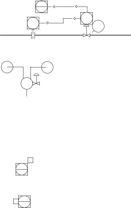
B.6.3 A typical instrument diagram developed from the PFD diagram:
|
|
I/P |
|
|
|
FIC |
FY |
|
|
|
*01 |
*01-A |
|
|
FE |
FT |
FY |
FV |
|
*01 |
*01-B |
|||
*01 |
||||
|
|
*01 |
||
|
|
|
a)Bubbles [FE-*01] and [FY-01-B] are optional and not recommended.
b)Bubble [FV-*01] is optional but is recommended.
Copyright International Society of Automation |
|
Provided by IHS under license with ISA |
|
No reproduction or networking permitted without license from IHS |
Not for Resale |
//^:^^#^~^^"#@::"~^$:~@""#:$@^"*^~@~$"~~""^^:@^^:#^~~\\
//^:^^#^~^^"#@::"~^$:~@""#:$@^"*^~@~$"~~""^^:@^^:#^~~\\
ANSI/ISA-5.1-2009 |
- 114 - |
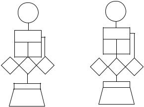
B.6.4 Typical equipment and function-oriented functional diagrams developed from the PFD diagram:
|
FT |
|
|
FT |
|
|
*01 |
|
|
*01 |
|
|
∆ |
|
|
∆ |
|
|
|
|
|
|
|
|
P |
I |
P |
I |
|
|
|
|
|
||
A |
T |
A |
A |
T |
A |
|
ƒ(x) |
|
|
ƒ(x) |
|
|
|
|
|
|
|
|
FV-*01 |
|
FV-*01 |
|
|
Equipment oriented |
Function oriented |
||||
B.7 Process variable measurements
B.7.1 Process variable measurement devices are inserted in or mounted on pipelines and equipment to measure a physical property or to analyze a chemical composition, and include but are not limited to:
a)Primary elements, such as orifice plates and thermocouples, that generate analog signals, position mechanical devices, or are used by transmitters to generate signals compatible with the control system.
b)Transmitters with integral primary elements, such as vortex shedding flowmeters and filled-capillary temperature devices that generate signals compatible with the control system.
B.7.2 Process measurements are indicated by:
a)Bubbles as shown in Table 5.2.1 for:
1)Generic primary elements.
2)Primary elements that do not have a graphic symbol in Table 5.2.3.
3)Users who elect not to use graphic symbols from Table 5.2.3.
b)Graphic symbols from Table 5.3.2.
B.7.3 Analyzer primary element located in a process slip stream or in a process stream or equipment with or without accessory devices, such as sample conditioners that contain components that are not normally shown, and with type of analyzer and component of interest noted at (**) and (***) respectively:
--`,,```,,,,````-`-`,,`,,`,`,,`---
Copyright International Society of Automation |
|
Provided by IHS under license with ISA |
|
No reproduction or networking permitted without license from IHS |
Not for Resale |
- 115 - |
ANSI/ISA-5.1-2009 |
a)With sample conditioners:
|
|
|
|
AE |
TC |
VENT |
|
|
|
|
(**) |
|
|
|
|
|
|
|
|
|
|
AE |
|
||||
|
|
|
|
|
or |
|
|
|
|
|
|||
|
|
|
*01 |
|
|
|
|
|
|
||||
|
|
|
|
|
|
|
|
|
|||||
|
|
|
C2 |
DRAIN |
|
|
|
*02 |
(***) |
|
|||
|
|
|
|
|
|
|
|
|
|
||||
|
|
|
|
|
|
|
|
|
|
|
VENT |
||
|
|
|
|
|
|
C3 |
|
|
|
|
|
||
|
AX |
|
|
|
|
|
AX |
|
|
||||
|
|
|
|
|
|
|
|
|
or |
||||
|
*01 |
SMPL |
|
|
|
|
|
*02 |
SMPL |
|
DRAIN |
||
|
|
|
|
|
|
|
|
|
|
||||
|
|
|
COND |
|
|
|
|
|
|
|
COND |
|
|
b)Without sample conditioners:
|
(**) |
|
|
|
|
TC |
VENT |
|
AE |
|
|
|
AE |
|
|
|
|
|
|
or |
|||
|
|
|
|
|
|
|
|
*01 |
|
|
|
*02 |
|
||
|
|
|
C2 |
DRAIN |
|||
(***) |
|
|
|
|
|||
|
|
|
|
|
|||
|
|
|
|
|
|
C3 |
|
c)Analyzer primary element or transmitter inserted in process stream or equipment:
AE |
MOIST |
AE |
pH |
|
|
||
*03 |
|
*04 |
|
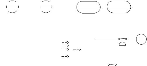
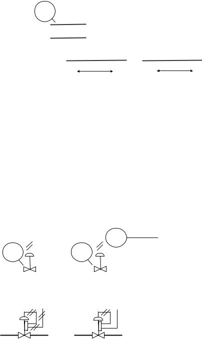
B.7.4 Orifice plate primary elements, with or without optional flow arrow, use generic orifice plate symbol with transmitter bubble connected to indicate orifice tap location for flange taps, corner taps, pipe taps, and vena contracta taps respectively:
a)Single process connection: corner taps, pipe taps, and vena contracta taps are indicated by notation:
FT |
FT |
FT |
FT |
*01 |
*01 |
*01 |
*01 |
|
CT |
PT |
VC |
b)Double process connection, pipe taps and vena contracta taps are indicated by notation:
FT |
FT |
FT |
FT |
*01 |
*02 |
*03 |
*03 |
|
|
PT |
VC |
B.7.5 Process root block valves should be shown as required by the piping engineering group.
//^:^^#^~^^"#@::"~^$:~@""#:$@^"*^~@~$"~~""^^:@^^:#^~~\\
--`,,```,,,,````-`-`,,`,,`,`,,`---
Copyright International Society of Automation |
|
Provided by IHS under license with ISA |
|
No reproduction or networking permitted without license from IHS |
Not for Resale |
//^:^^#^~^^"#@::"~^$:~@""#:$@^"*^~@~$"~~""^^:@^^:#^~~\\
ANSI/ISA-5.1-2009 |
- 116 - |
B.7.6 Orifice meter tubes or runs that are specified and requisitioned by the instrument group should be shown on drawings and sketches by:
a)Bubble: FX
|
*01 |
|
|
|
|
|
|
|
|
|
|
|
|
|
|
|
|
|
|
|
b) |
Notation: |
|
|
|
|
|
|
|
|
|
|
|
NOTES |
|||||||
|
|
|
|
|
|
|
|
|
|
|
||||||||||
|
|
|
|
|
|
|
|
|
|
|
||||||||||
|
|
|
|
|
|
|
|
|
|
|
||||||||||
|
|
|
|
|
|
|
|
|
|
|
||||||||||
|
|
|
|
NOTE 1 |
1. METER TUBE BY INSTRUMENTS. |
|||||||||||||||
|
|
|||||||||||||||||||
|
|
|
|
|
|
|||||||||||||||
|
|
|
|
|
|
|||||||||||||||
c) |
Flanged or welded: |
|
|
|
|
|
|
|
|
|
||||||||||
|
|
|
|
|
|
|
|
|
|
|
|
|
|
|
|
|||||
|
|
|
|
|
|
|
|
|
|
|
|
|
||||||||
|
|
|
|
|
|
|
|
|
|
|
|
|
||||||||
|
|
|
|
|
|
|
|
|
|
|
|
|
||||||||
|
|
|
|
|
|
|
METER RUN |
|
|
|
METER TUBE |
|
|
|||||||
|
|
|
|
|
|
|
|
|
|
|||||||||||
|
|
|
|
|
|
|
|
|
|
|
|
|
|
|
|
|
|
|
|
|
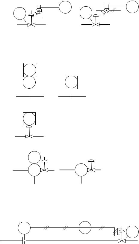
B.8 Final control elements
B.8.1 Final control elements installed in pipelines and equipment modulate or manipulate the process stream or equipment to affect the loop measured variable.
B.8.2 Final control elements include, but are not limited to, control valves, solenoid valves, louvers, dampers, motors, variable speed drives, and machine components.
B.8.3 Control valves are generally pneumatically operated and furnished with positioners that may:
|
a) |
Be actuated by a pneumatic or an electronic signal. |
|||||||||
|
b) |
Not be shown if all control valves are furnished with positioners. |
|||||||||
-- |
|
|
|
|
|
|
|
|
|
|
|
-`-`,,```,,,,```` |
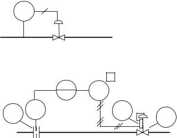
B.8.4 Control valves with pneumatic or electronic signal: |
||||||||||
|
|||||||||||
|
a) |
Without positioner: |
|
|
|
|
|
|
|||
`,,`,,`,`,,` |
|
|
|
|
I/P |
|
|||||
|
|
|
|
|
|
FY |
|||||
--- |
|
|
|
|
|
|
|
|
|
|
|
|
|
|
|
|
|
*01 |
|
|
|
||
|
|
|
|
|
|
|
|
|
|
||
|
|
|
FV |
|
|
FV |
|
|
|
|
|
|
|
*01 |
|
|
*01 |
|
|
|
|
|
|
|
|
|
|
|
|
|
|
|
|
|
|
b)With positioner:
1)Cross-hatches from positioner to actuator are optional.
Copyright International Society of Automation |
|
Provided by IHS under license with ISA |
|
No reproduction or networking permitted without license from IHS |
Not for Resale |
- 117 - |
ANSI/ISA-5.1-2009 |
c)With tripping solenoid, with and without positioner:
|
S |
LSL |
|
S |
LSL |
|
*11 |
FV |
*11 |
||
FV |
|
|
|||
|
|
|
|
||
*01 |
|
|
*01 |
|
|
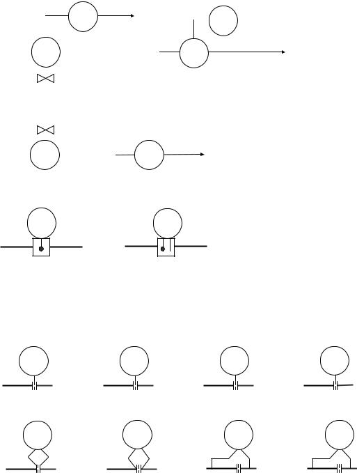
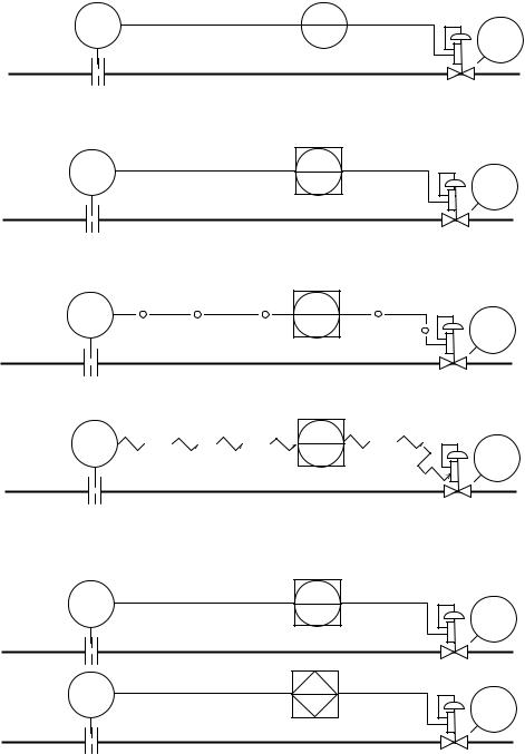
B.8.5 Instrumentation with integral components that:
a)Measure process variables and transmit control and other functions as an integral part of a transmitter:
FC *01
FT |
FC |
*01 |
*01 |
b)Manipulates control valves as an integral part of a control valve positioner:
FC *017
---`,,`,,`,`,,`-`-`,,```,,,,````--
c)Is an integral assembly that contains a transmitter, a controller, and a control valve:
FC 101
FT |
FV |
101 |
101 |
24VDC |
24VDC |
B.9 Common instrument-to-instrument signal connections B.9.1 Pneumatic discrete instrumentation:
FT |
FRC |
*01 |
*01 |
FV *01
Copyright International Society of Automation |
|
Provided by IHS under license with ISA |
|
No reproduction or networking permitted without license from IHS |
Not for Resale |
//^:^^#^~^^"#@::"~^$:~@""#:$@^"*^~@~$"~~""^^:@^^:#^~~\\
ANSI/ISA-5.1-2009 |
- 118 - |
|
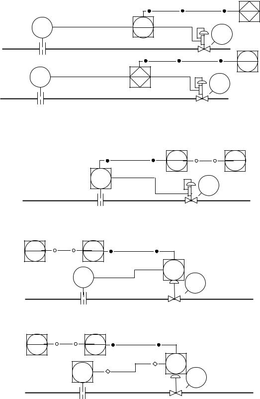
B.9.2 Electronic discrete instrumentation: |
|
|
FT |
FRC |
FV |
*01 |
*01 |
|
|
|
*01 |
B.9.3 Shared display, shared control instrumentation:
FT |
FRC |
FV |
*01 |
*01 |
|
|
|
*01 |
B.9.4 Shared display, shared control instrumentation, with diagnostic and calibration bus on field wiring:
FT |
FRC |
FV |
*01 |
*01 |
|
|
|
*01 |
B.9.5 Shared display, shared control and wireless instrumentation:
FT |
FRC |
FV |
*01 |
*01 |
|
|
|
*01 |
B.9.6 Shared display, shared control instrumentation, primary and alternate systems, no inter-bus communication:
FT |
FRC |
|
FV |
*01 |
*01 |
DCS-1 |
|
|
|
*01 |
|
|
|
|
FT |
FRC |
FV |
*11 |
*11 |
|
|
DCS-2 |
*01 |
---`,,`,,`,`,,`-`-`,,```,,,,````--
Copyright International Society of Automation |
|
Provided by IHS under license with ISA |
|
No reproduction or networking permitted without license from IHS |
Not for Resale |
//^:^^#^~^^"#@::"~^$:~@""#:$@^"*^~@~$"~~""^^:@^^:#^~~\\
- 119 - |
ANSI/ISA-5.1-2009 |
B.9.7 Shared display, shared control, primary and alternate systems, with inter-bus communication:
FT |
FC |
|
FV |
*01 |
*01 |
DCS-1 |
|
|
|
*01 |
|
|
|
|
FT |
FC |
FV |
*11 |
*11 |
|
|
DCS-2 |
*01 |
FI
*11
DCS-2
FI
*11
DCS-1
B.9.8 Shared display, shared control and fieldbus instrumentation, inter-bus communication:
a)Fieldbus transmitter/controller and electronic valve positioner:
SP |
FK |
FI |
|
*01 |
*01 |
FC |
|
FV |
*01 |
|
|
|
|
*01 |
b)Fieldbus valve positioner/controller and electronic transmitter:
FI |
FK |
SP |
*01 |
*01 |
|
FT |
|
FC |
|
*01 |
|
*01 |
|
FV |
|
*01 |
|
|
|
c)Fieldbus transmitter and valve positioner/controller:
FI |
FK |
SP |
*01 |
*01 |
|
|
FC |
|
FT |
*01 |
|
*01 |
FV |
|
*01 |
||
|
--`,,```,,,,````-`-`,,`,,`,`,,`---
//^:^^#^~^^"#@::"~^$:~@""#:$@^"*^~@~$"~~""^^:@^^:#^~~\\
Copyright International Society of Automation |
|
Provided by IHS under license with ISA |
|
No reproduction or networking permitted without license from IHS |
Not for Resale |
//^:^^#^~^^"#@::"~^$:~@""#:$@^"*^~@~$"~~""^^:@^^:#^~~\\
ANSI/ISA-5.1-2009 |
- 120 - |
B.9.9 Fieldbus valve positioner/controller, transmitter, and indicator:
|
FI |
|
|
*01 |
|
|
FC |
|
FT |
*01 |
|
*01 |
FV |
|
*01 |
||
|
B.9.10 Fieldbus integral transmitter, controller, and valve positioner:
|
|
|
FI |
|
|
|
|
FK |
|
||||
|
|
|
|
|
|
|
|
|
|
|
|
|
|
|
|
101 |
|
|
|
|
|
101 |
|
|
|||
|
|
|
|
|
|
|
|
|
|
|
|
|
|
|
|
|
|
|
|
|
|
|
|
|
|
||
|
|
|
|
|
|
FC |
|
|
|
|
|
|
|
|
|
|
|
101 |
|
|
|
|
|
|
|
||
|
|
|
|
|
|
|
|
|
|
|
|
||
|
|
|
|
|
|
24VDC |
|
|
|
|
|||
-- |
B.9.11 |
Instrument and functional |
|
diagrams should not be used to specifically identify signal tubing, |
|||||||||
|
wiring, and bus construction methods used to implement a monitoring and control system. |
||||||||||||
`,,`,,`,`,,`-`-`,,```,,,,```` |
|
||||||||||||
B.10 |
Function block symbols |
|
|
|
|
||||||||
--- |
|
|
|
|
|||||||||
|
|
|
|
|
|
|
|
|
|
|
|
|
|
B.10.1 Signal processing functions should be identified by a function block symbol from Table 7.6 that is:
a)Appended to a bubble if an Instrument/Tag Number is required:
Σ
FY
*012
b)Attached tangentially to the affected bubble and in line with the signal if the function is an integral part of the affected bubble:
Σ FI *012
Copyright International Society of Automation |
|
Provided by IHS under license with ISA |
|
No reproduction or networking permitted without license from IHS |
Not for Resale |