

See discussions, stats, and author profiles for this publication at: https://www.researchgate.net/publication/38146469
Overview of the DC power conversion and distribution
Article · October 2008
Source: OAI
CITATIONS |
READS |
13 |
762 |
1 author:
K.W.E. Cheng
The Hong Kong Polytechnic University
479 PUBLICATIONS 7,215 CITATIONS SEE PROFILE
Some of the authors of this publication are also working on these related projects:
voltage sag restorer View project
Design and application of a decoupled rotary-linear switched reluctance motor for concentrated photovoltaic power generation View project
All content following this page was uploaded by K.W.E. Cheng on 15 April 2016.
The user has requested enhancement of the downloaded file.
Asian Power Electronics Journal, Vol. 2, No. 2, Oct 2008
Overview of the DC Power Conversion and Distribution
K.W.E.Cheng1
Abstract – The DC distribution is discussed. A comparison of the DC distribution to conventional AC distribution has been made. The alternative method of high frequency AC distribution is addressed. DC distribution can often eliminate conversion stages. New methods of DC-DC power conversion have been reviewed. It can also facilitate the energy storage and enhance the reliability. Its application in electric vehicles is also described. Finally the future development of power electronics is highlighted.
Keywords - Power converter, DC distribution, AC distribution, motor drives, alternative energy, electric vehicle
I. INTRODUCTION
The DC distribution system is an alternative method for delivering power. The method has been proved to have advantages over conventional AC distribution in terms of energy saving, operation and cost. Thanks to the recent development in power electronics, the handling of the DC system including the voltage stepping, switching, DC energy storage is quite mature. In the last two decades, the rapid development in DC-DC power conversion is made in dramatic manner. New topology, analysis and control method have been reported. Therefore it is time to revisit such system and widen the opportunity to develop into a more practical establishment. Most of the electrical parts and systems are DC based. They may accept AC but internally have embedded with an AC-DC converter to obtain the necessary DC. For example, the computer units are derived by low voltage DC such as 3-20V. The motor drive inverter has also a DC link supplied by AC-DC rectifier. Most of the electronic lighting is now embedded with an electronic ballast which is also with a DC link of several hundred volts. The recent popular LED lighting is also a DC based system.
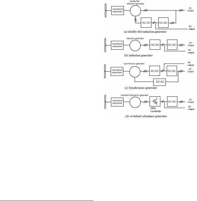
Most energy storage systems such as battery, hydrogen storage and ultra-capacitor are DC devices. Alternative energy sources such as photovoltaic is also DC source. Therefore it is straight forward to use DC distribution for power transfer and power conversion. Another major alternative energy source, wind power, can output DC as well. Fig. 1 shows the configuration. The driver or power converter for the generator has a DC link.
Nowadays, the wind power generation has biased to direct drive because of efficiency and elimination of the mechanical parts. The use of DC link will be advantageous because it allows a buffer stage to convert the variable frequency or low frequency from the generator side through an intermediate stage to the output stage. An inverter (AC-DC) is connected in the AC line using grid connection control. If DC distribution is used, the grid connection inverter can be eliminated.
The paper first received 25 Feb 2008 and in revised form 25 Aug 2008 Digital ref: Al70301217
1 Power Electronics Research Center, Dept. Elect. Eng., The Hong Kong Polytechnic University, Hong Kong. E-mail: eeecheng@polyu.edu.hk
The control through joining different DC generator sources in a station is simple because there is no frequency and phase synchronization. DC system is not new. It has been used in office and factory areas for local distribution. It has also been used in aerospace system. This includes aircraft, space, and maritime DC distribution. Obviously the future applications will be moved to consumer level including buildings, home and office.
Fig. 1: Wind power energy source
Despite the rapid development in the DC system and power electronics, the development of such DC distribution has still a number of problems to be resolved. These include the fault detection, DC switching, stability, startup and shutdown, overall system issue and cost issue. This paper is focused on low voltage systems rather than the high voltage systems, as the high voltage transmission has been well discussed in many reports and has been used extensively for power cross-country power transmission.
II.DC DISTRIBUTION
A.Previous work on DC distribution
DC distribution network has a number of well-known advantages as compared with the conventional AC distribution. The applications in general buildings [1], maritime shipboard [2] and aerospace environment [3] have been reported. The main reason of not being widely used for the last decade extensively is mainly
75

economic reasons and partly because of the conservation of engineers. Today, the rapid development of power electronics provides an opportunity of this method because it allows DC conversion to be easily applied. As we know, most energy sources can produce DC voltage, by this; we mean fuel cell, photovoltaic cell and even many generators. Many energy storages these days are also DC, including capacitor, inductor and battery. The use of DC distribution undoubtedly has better cost implication and higher efficiency because of fewer conversion stages. The recent DC to DC power conversion research in the field of power electronics has also given additional favourable method of this DC distribution. The DC distribution has been used successfully in high voltage DC system [4-5] and many micro-distribution systems in electric vehicles [6]. However there are still a number of research difficulties that needs to be tackled before it can be realized for industrial use. The following are some researches reported on this topics:
The low voltage DC distribution has been reported by several researchers recently. The main work on these areas entail the fault detection based on the impedance characteristics [7-8]. This method is based on checking the impedance of individual modules against their specifications. The circuit breakers modeling for the DC distribution system (DDS) based on PSpice [9] has been reported. The model can further be implemented to simulate the whole protection system. The electronic circuit breaker for the DC system has been reported based on the zero-voltage switching [10]. The switch uses auxiliary circuit of RCD snubber for the assistance to the improvement of the switching transient. The switching time of 200μs has been simulated.
The PEBB (power electronics building block) is a concept to provide generic building blocks for power electronics. It has been recently reported [11] for use in DDS. This idea can be extended to the future larger scale DC distribution in buildings and other systems.
The stability study on the DC distribution system has been reported by Logue [12]. The negative incremental impedance can cause stability problems and this is especially important for DC conversion network where the energy storage components such as the passive devices in the distribution line and load side exist and cause unwanted stability problems. Some early study on the load impedance on the stability in the distribution systems has been reported [13]. Some initial studies on the bulk capacitance and the load changes on the stability have been reported [14].
B. EMI for DC distribution
The EMI is also a concern in the DC distribution. There have been many international standards on AC distribution and EMI on various AC systems and DC conversion electronics, however, on the consideration of DC distribution is limited. The proposed standard for 48V rail [15] is an initial step in this direction. Similarly, although there are extensive researches conducted in the EMI properties on DC power conversion, the study on the EMI effect on DC distribution buses has been less thoroughly studied. Ref [16] is the modeling of the interference properties on this topic.
Cheng K.W.E: Overview of DC…..
C. Protection and power quality on DC distribution
The use of switched mode for current protection has been reported in [17]. The stabilization of DC distribution is affected by the cable, capacitive load, inductive load and load changes. A controlled auxiliary power through bulk capacitance has been proposed in [18]. A control logic for different operating conditions has also been examined for low voltage DC distribution system [19].
D. The saving in DC distribution
The DC distribution allows saving in cable size, rectifier or AC-DC converter, equipment or appliance materials and package size. The saving in the loss of power processing can also be reduced because the rectifier stage is reduced. For the AC power source related system such as interruptible power supply (UPS), the inverter stage can also be reduced. The following table gives an estimation of the potential saving.
Table 1: Estimation saving using DC distribution
|
Size |
Power input |
|
reduction |
reduction |
|
|
|
Electronic ballast |
30% |
5% |
|
|
|
Motor inverter |
30% |
4% |
|
|
|
Renewable energy system |
40% |
5% |
|
|
|
Distribution |
50% |
2% |
|
|
|
Low power Charger |
20% |
10% |
|
|
|
Video/Audio Entertainment |
10% |
10% |
|
|
|
Computer |
15% |
8% |
|
|
|
Average |
25% |
4.50% |
Other advantages including the audible emission will be eliminated as many equipment or appliances will emit 50/60Hz noise under poor design or aged condition. Further, the quality of the entertainment system will be improved because it is free from interference of mains frequency. The 100/120Hz flickering of many lighting units will also disappear.
III.DC DISTRIBUTION VERSUS AC DISTRIBUTION
A. Conventional low frequency AC
The discussion of the comparison of DC and AC distribution has been made in many literatures in the past. It is obvious that the DC distribution has many advantages over conventional system. The main reason for the unwillingness of change is because the world has adapted to the AC system for many years. The change cannot be sudden and must be made gradually. It is also expected the change should start in a smaller scale such as office or a section of a plant.
B. High frequency AC
Recently there is discussion on the use of high frequency AC distribution. The use of high frequency AC is not new. The aerospace standard has used 400Hz for years because of the reduction of the passive components. Higher frequency has been discussed extensively in recent publications [20-21] in the comparison and switching waveforms. The main advantage of high frequency AC distribution is the reduction of the filter and reactive
76
Asian Power Electronics Journal, Vol. 2, No. 2, Oct 2008
components. It also increases the transient response as just a few cycles of reaction time refers to a fraction of ms.
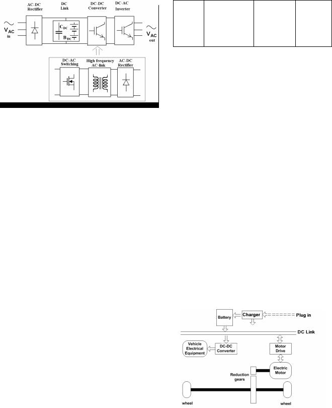
Fig. 2: High frequency AC-link is embedded to DC converter
The DC-DC power conversion uses high frequency AC link for power transfer. There is at least one high frequency transformer or inductor for voltage stepping or temporary energy storage. AC distribution has been used inside most of the DC-DC power conversion. Fig 2 shows the block representation.
For general AC-AC power converter such as variable speed drive (VSD) for motors, if wide voltage variation is needed, DC-DC power converter is also needed. The high frequency AC-link is then also embedded in the unit. It is rational to examine if the high frequency AC-link should be used and how it is compared with the DC link.
Using high frequency AC link will have the same problem of the synchronous of frequency and phase when different voltage sources are added in either parallel or series. The high frequency loss is a factor to be overcome. Therefore, the cable, inductor and transformer design must be properly developed. Care must be taken for skin effect and proximity effect, otherwise, the loss and heating effect in the conductor will cause operation and life time problem [22-24].
C. Health issue
The high frequency AC may generate biological effect to human[25]. The standard [26] has shown that exposure to AC frequency for general public should be less than 10kV/m to 0.4kV/m for electric field and 0.64mT to 0.021mT for magnetic field from 50Hz to 10kHz respectively. The International Commission on NonIonizing Radiation Protection (ICNICP) [27] has recommended that the electric and magnetic field should be 10V/m to 610V/m and 0.4A/m to 1.6A/m from 50Hz to 100kHz. The National Radiological Protections Board (NRPB) has also published their guideline on the exposure limits [28]. Tables 1 and 2 shows the comparison of different standards:
Table 1: Exposure limits to electric field for public
|
ENV50166-1 |
ICNIRP |
NRPB |
|
|
|
|
50Hz |
10kV/m |
10kV/m |
12.28kV/m |
|
|
|
|
10kHz |
0.4kV/m |
87V/m |
614V/m |
|
|
|
|
100kHz |
- |
87V/m |
614V/m |
|
|
|
|
Table 2: Exposure limits to magnetic field for public
|
ENV50166-1 |
ICNIRP |
NRPB |
|
|
|
|
50Hz |
0.028mT |
0.1mT |
2mT |
|
|
|
|
10kHz |
0.021mT |
6.25μT |
0.2mT |
|
|
|
|
100kHz |
- |
9.2μT |
0.06mT |
The exposure limit for power frequency (50/60Hz) is high because it carries too little energy in each quantum to break chemical and molecular bonds. The heating effect by the power frequency is very low as compared to the human body’s own background rate of heat generation. For high frequency, the innovation effect and other high frequency damage will be increased dramatically and the limit is much lower. However, the actual damage due to power of high frequency is difficult to be studied as it requires an actual model. The long duration exposure under lower than the exposure limits has no established study and it is recommended to avoid consistent contact to such field. Therefore the use of DC may have advantages against the DC distribution for such argument.
IV. DC DISTRIBUTION IN ELECTRIC VEHICLE
A. The more electric vehicle
Electric vehicle is a good system that shows a combination of different power electronic units. It includes the DC battery system, battery charger, DC-DC power conversion, DC-AC inverter for motor drive as shown in Fig. 3. Fig. 4 shows a typical electric vehicle that has demonstrated the application of power electronics and DC distribution. Each of the unit requires substantial power electronics work. The electric vehicle is not restricted to automobile, other vehicle such as aircraft [29] and or ship [30] has also been examined for DC distribution. The More Electric Aircraft concept has been promoted in the last 2 decades because of the rapid development in power electronics. Many actuation and control system are power electronic driven. The use of DC distribution will enhance power and dynamic performance. The following discusses the recent development in electric vehicle:
Fig. 3: Typical configuration of electric vehicle
B. DC conversion in vehicle
Electric vehicle is a standalone network and it is using battery as the main power. The hybrid electric vehicle also uses battery as an intermediate stage for electric motor. There are lots of works for DC power conversion
77
so that the battery voltages can be converted to different levels for equipment.
Cheng K.W.E: Overview of DC…..
conventional angle steering as the steering method for tank. The mechanical subsystem including the gear box, clutch, transmission and other actuator and hydraulic system can be eliminated. The saving in heavy and bulky mechanical and hydraulic units will increase the overall efficiency and reduce materials.
Fig. 4: Electrical vehicle DC system
C. Battery charging and management
The recent development is towards the design for intelligent charging for high performance battery such as Li-ion[31] and battery management system [32]. The battery management should provide battery balancing, determining the State of Charge (SoC) and State of Health (SoH).
The battery charger is actually an AC-DC converter. For low power application, the flyback converter is commonly used because of its low component count; for higher power level such as hundreds of Watt or above, the H- bridge converter is commonly used.
D. Motor drive
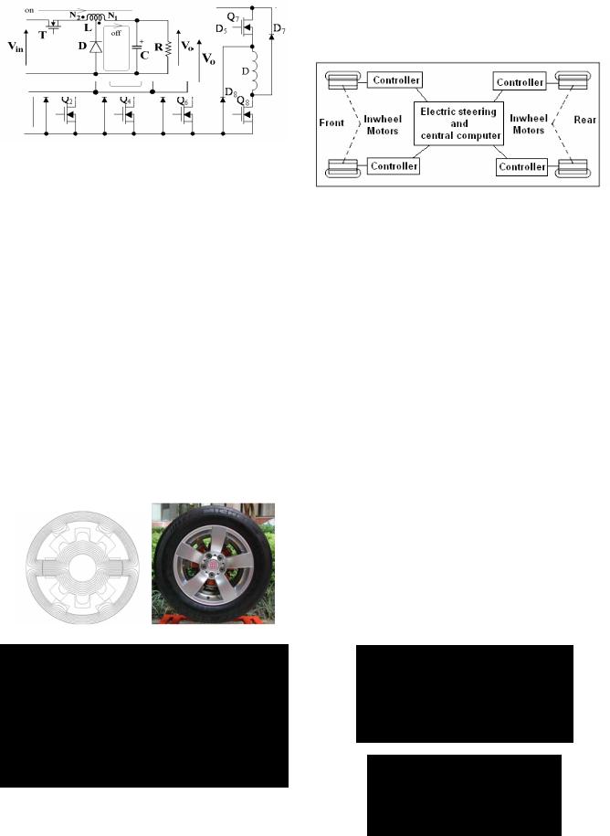
The motor drive for electric vehicle is to convert from DC battery to switched waveforms to drive the motor. The DC drive for DC motor is commonly used for low power. The H-bridge converter is used because it provides 4- quadrant control. The induction motor is driven by conventional 3-phase inverter. Commonly, the switchedreluctance motor (SRM) is considered for high performance motor drive. The new SRM is designed using in-wheel method in which the stator is in the center and the rotor is in the outer. An 8/6 motor and the drive is shown in Figs. 5 and 6.
Fig. 5: 8/6 in-wheel motor
Fig. 6: The SRM drive for 8/6 motor
The in-wheel motor can replace the wheel as shown in Fig 7. The method allows the skid-steering rather than the
Fig. 7: Four-wheel drivetrain system
V. DC-DC POWER CONVERSION
In order to facilitate the application of DC distribution, the use of switched mode power conversion is necessary. For general voltage conversion, the classical topology can be used, for example, the Buck, Boost or Buck-boost. For isolated application, the use of transformer or coupledinductor circuit topologies is used, for example, flyback converter or forward converter. For high power application, full bridge topology should be used. The typical circuit is phase-shifted converter [33] or loadresonant converter [34]. If soft-switching is needed such that the softer current or voltage is needed to reduce the switching transient, the quasi-resonant [35], extendedperiod resonant [36] or the resonant transition [33-34] can be used. There are a number of new topologies now available for DC-DC power conversion. They are discussed as follows:
A. Tapped inductor
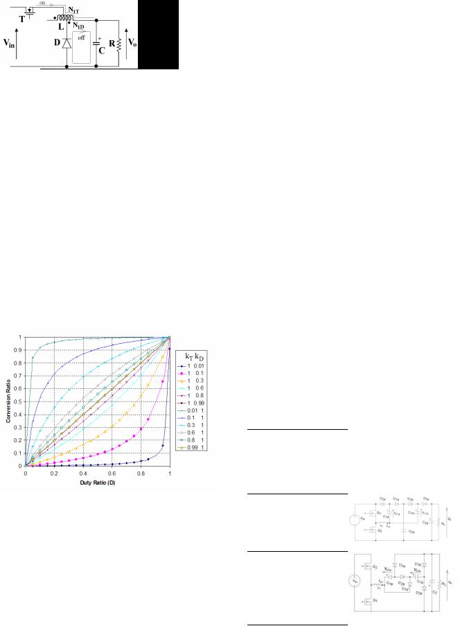
The non-isolated converter can be used for applications of fixed and non-human-contacted equipment or the EMI concern is not an issue. Recently the tapped inductor converter is promoted by [37] because of it’s simple in structure and wide voltage conversion range while maintaining high efficiency. The tapped inductor is basically derived form the conventional power converter and allows taps of the inductor to connect to either the transistor or diode or both. This allows a wide range of voltage conversion. For example, a buck converter can be developed into three types as shown in Fig. 8.
(a)Transistor-tapped
(b)Diode-tapped
78
Asian Power Electronics Journal, Vol. 2, No. 2, Oct 2008
(c) Transistor-diode-tapped
Fig. 8: Buck tapped inductor circuit
If the tapped ratios k, kT and kD are given by: |
|
|||||||
k = |
N1 ; |
kT |
= |
N1T ; |
kD = |
N1D |
(1) |
|
N12 |
|
N12 |
N12 |
|
||||
|
|
|
|
|
||||
where N12 is the total number of turns, then, the voltage conversion ratio under continuous mode for each circuit is a function of the duty ratio D and the above k ratios:
Vo |
= |
D |
Vin |
D(1 − k) + k |
|
|
|
Vo |
= |
|
kD |
(3) |
||
|
|
V |
|
|
1 − D + kD |
|
|
|
|
|
in |
|
|
|
|
|
|
|
|
Vo |
= |
|
kDD |
(4) |
||
|
Vin |
|
|
(1− D)kT +kD D |
|
|||
for transistor-tapped, diode-tapped and transistor-diode tapped respectively. The conversion ratio for each circuit has been plotted in Fig 9. It can be seen that the conversion ratio for transistor-diode tapped version covers the conversion ratio from 0 to 1 for any duty ratio. Experimental results has indicated that the converter has high efficiency even under wide conversion ratio.
Fig. 9: Voltage conversion ratio for the transistor-diode tapped Buck converter
B. Switched-capacitor
Recently there are a number of discussions on the switched-capacitor resonant converter and its advantages against the conventional switched mode power converter and the classical switched capacitor converter [38-39]. There are comments made in [40-41] that the switchedcapacitor resonant converter does not have voltage regulation which is supposed to be the mandatory condition for all power converters. Further, the loss is not related to the component loss characteristics. It is noted that the switched-resonant converter is an improved development of the conventional switched-capacitor converter. The methods [38-39] have quantified the
amount of the inductance needed in order to control the resonant property of the converter. The inherit voltage regulation is within 10%. The resonant converter is suitable for applications with less demand on exact voltage regulation such as a DC-DC transformer. The conventional converters [40-42] do have theoretical efficiency independent of components but its practical efficiency is strongly dependent on components.
In the conventional method, the amount of the parasitic inductance is uncontrolled or ignored and therefore the loss due to the switching is also not controlled and the switching loss and noise are resulted. The readers have to consider carefully which method they should use. The comparison is as follows:
|
Conventional |
|
|
|
Resonant |
|
|
||||
Magnetic |
No magnetic |
components, |
Small |
inductor |
is |
||||||
components |
use uncontrolled parasitic |
needed. |
|
|
|
||||||
Current |
High |
|
|
|
|
|
Low |
|
|
|
|
stress |
|
|
|
|
|
|
|
|
|
|
|
Number of |
Depends |
on |
the circuit, |
Two transistors |
|
||||||
transistors |
usually |
many |
especially |
|
|
|
|
|
|||
|
for |
high |
fractional |
or |
|
|
|
|
|
||
|
multiple ratio |
|
|
|
|
|
|
|
|
||
Efficiency |
Low. |
Depend |
on |
the |
Theoretical |
100%, |
|||||
|
voltages |
of |
|
switching |
practical |
higher |
|||||
|
capacitors, |
input |
and |
than 90% |
|
|
|||||
|
output voltages. |
Practical |
|
|
|
|
|
||||
|
efficiency is low |
|
|
|
|
|
|
|
|||
Power level |
Low |
power, |
usually |
less |
No |
restriction |
on |
||||
|
than 100W |
|
|
|
power |
|
level. |
||||
|
|
|
|
|
|
|
Reported |
power |
|||
|
|
|
|
|
|
|
level |
is |
more than |
||
|
|
|
|
|
|
|
1kW. |
|
|
|
|
The new version of the switched–capacitor resonant converter has been reported in many literatures. Fig. 10 shows the family of the converters and its voltage conversion ratio M.
|
|
|
Basic |
Higher order |
||||
Step down |
|
|
|
|
|
|
|
|
|
|
|
|
|
|
|
|
|
|
|
|
|
|
|
|
|
|
|
|
|
M=0.5 |
|||||
|
|
M=1/3 |
||||||
Step up |
|
|
|
|
|
|
|
|
|
|
|
|
|
|
M=3 |
||
|
|
|
M=2 |
|||||
Inverting |
|
|
|
|
|
|
|
|
|
|
|
|
|
|
|
|
|
|
|
|
|
|
M= -1/2 |
|||
|
|
|
M= -1 |
|||||
Fig. 10: The family of switched-capacitor resonant converter
Other new development in multiple output and power factor correction can be referred to [43-44].
79
VI. MAGNETICS
Magnetic device is one of the basic components on DC power conversion because it provides temporary energy storage, isolation and voltage stepping. Besides the development of ferrites and Molydbenum Permalloy Powder (MPP) in the last tens of years, there is no advance development in the magnetic materials. The latest development in magnetics can be reported in the following two areas:
A. Polymer-bonded magnetics
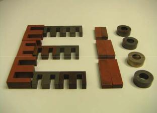
High frequency power conversion usually requires air-gap or distributed air-gap in order to reduce the overall permeability and saturation of ferrites and iron core. The invenion of the polymer-bonded magnetics [45] meets this need; it is directed to a magnetic composition containing a thermoplastic resin and magnetic powders. The new material is to combine resins such as PMMA or PE with magnetic powder taken from Nickel, Cobalt, NiZn Ferrite, and MnZn Ferrite and together with a coupling agent. The new material is shown in Fig 11.
Fig. 11: Different sizes and shapes of polymer-boned magnetic core
The new material has the advantages of non-brittle, flexible shape, lower loss, lower cost and simpler manufacturing procedure. The material can also be recycled as it is plastic based.
B. Coreless transformer
At very high frequency operation, the permeability of the magnetic core of the transformer can be reduced and at some stage, an air-core can be used [46-47]. At present, as the switching frequency cannot be moved to several or tens of megaHetz, the operation frequency of air-core transformer based power converter has been reduced slightly. For air core transformers, self-resonance can be used to minimize the magnetizing current in the external circuit.
VII. FUTURE POWER ELECTRONICS FOR DC
Power electronics provides simple and higher efficiency power processing for DC-DC operation. The future development of DC power electronics will have the following trends:
Cheng K.W.E: Overview of DC…..
A. Energy saving and environment
Energy saving and development of new energy are the most important global concern. Power electronics provides efficient power processing methodologies. Today, power electronics has been used in many alternative energy sources. Power electronics has found its application in wind power generation, photovoltaic, energy storage, hydropower, and power quality compensation. It can also be seen that higher power circuit topologies and devices are being further developed for demanding applications.
B. New switching devices
Power electronics heavily depends on the power devices. The rapid development in power electronics is partly because of the new devices. The higher speed, low onstate resistance or voltage, capability of handling high power are the trend of the last 20 years’ development in switching devices. In 80’s Mosfet, IGBT, MCT are popular devices and are still popular. In recent years, integrated gate-commutated thyristor (IGCT) is available with forward and reverse blocking features. The successful development of IGBT is replacing Gate turn-off thyristor (GTO). Silicon Carbide (SiC) is the large bandgap (3eV) material device and is now believed to bring power electronic device to higher performance. [4850]. It provides all the above good performance as well as high junction temperature. Its thermal conductivity is good (5W/cm°C)[50]. Gallium Nitride (GaN) is also considered for power switching device. It has higher bandgap (3.4eV) and good thermal conductivity of over 1.3 W/cm°C. It is expected that the new devices will bring new revolution of power electronics.
C. New materials and passive devices
Power electronics strongly depends on passive components, which are also affected by new devices. The development of ferrites provides a new method of temporary energy storage, maintaining high efficiency of more than 99% in the magnetic devices. Higher saturation level and lower loss in hysteresis, eddy current and residual losses are needed. The new magnetic material such as polymer bonded magnetic device has proved to be efficient at high frequency. The use of CoNiFe alloy has been reported [52]. Recent devices such as ultra-capacitors allow high energy density and reduce transients which affect the battery life time. Higher temperature magnetic energy storage is also expected to provide new opportunity and application of power electronics.
D. Standards and safety
International standard is usually addressed to safety and creating a balance among different parties. Over the years, a number of new standards such as EMC and energy saving guidelines have forced power electronics to work in new methods. For example the Restriction on Hazardous Substances (RoHS) [53] which came into force on 1 July 2006, has changed the manufacturing and components procurement for all the power conversion design and production.
80
Asian Power Electronics Journal, Vol. 2, No. 2, Oct 2008
E. Cross disciplines
Power electronics is a supporting technology. Besides power processing, power electronics has found new applications in medical electronics, automotives, lightings and building services. It is clear that any discipline or technology that requires power and motion control is likely to work with power electronics to improve the overall performance in size, stability and dynamic performance.
F. Integration
The demand by intelligence and high power density is a development trend. There are intelligent power modules (IPM) that integrate the gate drive and protection into power devices. It simplifies application design of the power stage of the motor drive, inverter and power converter. Intelligent power electronics module (IPEM) that integrates the power electronics circuit with sensors and controllers has been reported [54]. The integration of magnetics into power devices [52] is also a trend. The integration of the power electronics into motors and batteries is developing. The in-wheel motor shown in Section IIB is a step of integration of intelligent motor. Another example is the embeddedment of battery management system (BMS) and voltage regulation into the battery.
VIII. CONCLUSION
An overview of the DC-DC power conversion is given. The paper discussed the recent development in DC-DC power converters, DC distribution, DC driven motor, electric vehicle and magnetics. A number of new converters including the tapped and switched-capacitor have been discussed. It outlines the major differences between new converters and conventional converters. The DC distribution and the AC distribution have also been compared. The paper finally summarises the latest power electronics applications, discusses the present development in DC power electronics and provides a future direction of the DC power conversion.
ACKNOWLEDGMENT
The author gratefully acknowledge the financial support of The Hong Kong Polytechnic University under project 1- BB86, The Innovation Technology Fund under project ITF/013/07AP for the work.
REFERENCES
[1]F.Wicks, “Evaluating alternatives for integrating distribution DC generation with AC power systems”, Energy Conversion Engineering Conference and Exhibit, 2000, Vol. 2, pp. 763-766.
[2]P.Chester, “Shipboard electrical power architecture”, Control Technology Workshop Proceedings, Blackburg, VA, April 1995, pp. 100-110.
[3]M.E.Elbuluk, S.Gerber, A.Hammoud and R.L.Patterson, “Performance of power converters at cryogenic temperatures”, Electronics, Circuits and Systems, 2001, Vol. 1, pp. 153-156.
[4]T.Hayashi, “Power system growth and use if new techniques in Japan”, IEE Power Engineering Review, Vol. 21, Issue 2001, pp. 12-14.
[5]J.P.Hull, “HVDC light improves efficiency, reduces emissions”, Offshore Magazines, April 1, 2003.
[6]S.W.Anderson, R.W.Erickson, R.A.Martin, “An improved automotive power distribution system using nonlinear resonant switch converters:, IEEE Trans. on Power Electronics, Jan 1991, Vol. 6, Issue 1, pp. 48-54.
[7]X.Feng, Z.Ye, C.Liu, R.Zhang, F.C.Lee, D.Boroyevich, “Fault detection in DC distribution power systems based on impedance characteristics of modules”, Industry Applications Conf. 2000, Vol. 4, pp. 2455-2462.
[8]X.Feng and F.C.Lee, “On-line measurement on stability margin of DC distribution power system”, Applied Power Electronics Conference and Exposition 2000, Vol. 2, pp. 1190-1196.
[9]T.Robbins, “Circuit-breaker model for over-current protection simulation of DC distribution systems”, Telecommunjications Energy Confernece 1995, Oct, pp. 628-631.
[10]P.van Gelder and J.A.Ferreira, “Zero-volt switching hybrid DC circuit breakers”, Industry Applications Conference 2000, Vol. 5, pp. 2923-2927.
[11]G.S.Thandi, R.Zhang, K.Xing, F.C.Lee and D.Boroyevich, “Modeling, control and stability analysis of a PEBB based DC DPS”, IEEE Transactions on Power Delivery, Vol. 14, Issue 2, April 1999, pp. 497-505.
[12]D.L.Logue and P.T.Krein, “Preventing instability in DC distribution systems by using power buffering”, Power Electronics Specialists Conference 2001, June, Vol. 1, pp. 33-37.
[13]C.M.Wildrick and F.C.Lee, “A method of defining the load impedance specification for a stable distributed power system”, IEEE Trans on Power Electronics, Vol. 10, No. 3, May 1995, pp. 280-285.
[14]D.J.Thompson, “DC voltage stabilization control in telecommunication DC distribution systems”, Telecommunications Energy Conf. 2002, Oct., pp. 74-78.
[15]N.Tullius, N.Korbel and A.Ashdown, “Propsoed Standard for transients on the 48V rail”, Telecommunication Energy Conference, 1997, Oct, pp. 384-388.
[16]B.A.Bowles, “Modelling interference properties of SMPS DC power distribution busses”, IEEE National Symposium on Electromagnetic Compatibility, 1989, pp. 119-126.
[17]C.Jin and R.Dougal, “Current limiting technique based strategy for an industrial DC distribution system”: IEEE ISIE, July 2006, Montreal, pp. 820-825.
[18]D.J.Thompson, “DC voltage stabilization control in telecommunications DC distribution systems”, 24th Annual International Telecommunications Energy Conference, INTELEC, 29 Sept.-3 Oct. 2002, pp. 74 – 78.
[19]M.Renna, G.C.Lazaroiu, E.Tironi, “High power quality and DG integrated low voltage dc distribution system”, IEEE Power Engineering Society General Meeting, 2006, 6 pages, CD Rom.
[20]S.Luo, I.Batarseh, “A review of distributed power systems. Part II. High frequency AC distributed power systems”, IEEE Aerospace and Electronic Systems Magazine, Vol. 21, Issue 6, Part 2, June 2006, pp. 5 – 14.
[21]M. Qiu, P. K. Jain and H. Zhang, “Dynamic performance of an APWM resonant inverter fir high frequency AC power distribution system”, IEEE Trans. power electronics Vol. 21, No. 6, Nov 2006, pp. 1556-1563.
[22]K.W.E.Cheng and P.D.Evans, “Calculation of winding lossess in high frequency toroidal inductors using single strand conductors”, IEEE Proceedings-Electr. Appl., Vol. 141, No. 2, pp. 52-62, March 1994.
[23]K.W.E.Cheng, “Computation of the AC Resistance of Multistranded Conductor Inductors with Multilayers for High Frequency Switching Converters”, IEEE Transactions on Magnetics, Vol. 36, No. 4, July 2000, pp. 831-834.
[24]K. W. E. Cheng, “Modeling of Solenoidal Transformer for the Calculation of Leakage Inductance Using Eddy Current Reaction Field”, IEEE Trans on Magnetics, Vol 41, Issue 5, May 2005, 1996 – 1999.
81

[25]F.Fitzgerald, I.Nair and M.Granger, “Electromagnetic fields: the jury’s still out”, IEEE Spectrum, Vol. 27, Aug 1990, pp. 23-25.
[26]Human exposure to electromagnetic fields – Low-frequency (0Hz to 1kHz), ENV50166-1, 1995.
[27]“Guidelines for limiting exposure to time-varying electric, magnetic and electromagnetic fields (up to 300GHz)”, ICNIRP guidelines, Health Physics Society, 1998, pp. 494522.
[28]“Guidance as to restrictions on exposures to time varying electromagnetic fields and the 1998 recommendations of the international non-ionizing radiation committee”, National Radiological Protection Board, 1989.
[29]O.R.Adefajo, M.Barnes, A.C.Smith, S.A.Long, D.R.Trainer, A.Abdel-Hafez, A. Forsyth, J.Chivite-Zabalza, A.Cross, R.Todd, “Voltage control on an uninhabited autonomous vehicle electrical distribution system”, 4th IET Conference on Power Electronics, Machines and Drives, PEMD, April 2008, pp. 676 – 680.
[30]H.Hamilton, H.; N.N.Schulz, “DC Protection on the Electric Ship”, IEEE Electric Ship Technologies Symposium, 2007. ESTS '07, May 2007, pp. 294 – 300.
[31]Y.S. Lee; M.W. Cheng, “Intelligent control battery equalization for series connected lithium-ion battery strings”, IEEE Transactions on Industrial Electronics, Vol. 52, Issue 5, Oct. 2005, pp. 1297 – 1307.
[32]S.Duryea, S.Islam, W. Lawrance, “A battery management system for stand-alone photovoltaic energy systems”, IEEE Industry Applications Magazine, Vol. 7, Issue 3, May-June 2001, pp. 67 – 72.
[33]Chan H.L., Cheng K.W.E., and Sutanto D., “Phase-shift controlled DC-DC converter with bi-directional power flow”, IEE Proceedings-Electr. Power Appl., Vol. 148, No. 2, March 2001, pp. 193-201.
[34]R.L.Steigerwald, “A comparison of half-bridge resonant converter topologies”, IEEE Transactions on Power Electronics, Vol. 3, Issue 2, April 1988, pp. 174 - 182
[35]K.H.Liu, F.C.Lee, “Zero-voltage switching techniques in DC/DC converters”, IEEE Trans Power Electronics, 1990, Vol. PE-53, pp. 293-304.
[36]K.W.E.Cheng and P.D.Evans, ‘The unified theory of extended-period quasi-resonant converter’, IEE Proceedings-Electr. Power Appl., Vol. 147, No. 2, March 2000, pp. 119-130.
[37]K.W.E.Cheng. “Tapped inductor for switched-mode power converters”, International Conference on Power Electronics and System Applications, Nov 2006, pp. 14-20.
[38]K.K.Law, K.W.E.Cheng and Y.P.B.Yeung, “Design and analysis of switched-capacitor based step-up resonant converters”, IEEE Trans Circuit Systems I, Vol.52, Issue 5, May 2005, pp. 943-948.
[39]Y.P.B.Yeung, K.W.E.Cheng, S.L.Ho, K.K.Law and D.Sutanto, “Unified analysis of switched-capacitor resonant converters”, IEEE Trans Ind. Electronics, Vol. 51 , Issue: 4 , Aug. 2004, pp.864 – 873.
[40]A.Ioinovici, C.K.Tse, H.S.H.Chung, “Comment on Design and analysis of switched-capacitor based step-up resonant converter”, Vol. 53, Issue 6, June 2006, pp.1403.
[41]A.Ioinovici, H.S.H.Chung, M.Makowski and C.K.Tse, “Comments on Unified analysis of switched-capacitor resonant converters”, IEEE Trans Industrial Electronics, Vol. 54, No. 1, Feb 2007, pp. 684-685.
[42]A. Ioinovici, “Switched-capacitor power electronics circuits,” IEEE Trans. Circuits Syst. Mag., Vol. 1, No. 3, Jul. 2001, pp. 37-42.
[43]Y.P.Yeung, K.W.E.Cheng and D.Sutanto, “Investigation of multiple output operation for switched-capacitor resonant converters”, Int.J. Circuit Theory & App, Vol. 30, Issue 4, Mar 2002, pp. 411-423.
[44]K.K.Law and K.W.E. Cheng, “Examination of the frequency modulation and lifting techniques for the generalized power
82
Cheng K.W.E: Overview of DC…..
factor correction switched-capacitor resonant converter”, International Journal of Circuit Theory and Application, 15 Nov 2007, cta.462.
[45]Wei-Tai Wu, Y.W. Wong and K.W. Eric Cheng, “Temperature Dependence of Magnetic Properties of a Polymer Bonded Magnetic Material”, Int. Conf. Power E.
Sys. and App., PESA 2006, Nov 2006, pp. 73-76.
[46]H.L Chan, K.W.E.Cheng and D Sutanto., “Calculation of Inductances of High Frequency Air-core Transformers with Superconductor Windings for DC-DC Converters”, IEE Proceeding-Electric Power Appl., Vol. 150, Issue 4, July 2003, pp. 447-454.
[47]S.C.Tang, S.Y.Hui, H.S.H.Chung, “A low-profile low-power converter with coreless PCB isolation transformer”, IEEE Transactions on Power Electronics, Vol. 16, Issue 3, May 2001, pp. 311 - 315
[48]F.Blaabjerg, A.Consoli, J.A.Ferreira, J.D.van Wyk, “The future of electronic power Processing and conversion”, IEEE Transactions on Power Electronics, Vol. 20, Issue 3, May
2005, pp. 715 – 720.
[49]A.Emadi, S.S.Williamson, A.Khaligh, “Power electronics intensive solutions for advanced electric, hybrid electric, and fuel cell vehicular power systems”, IEEE Transactions on Power Electronics, Vol. 21, Issue 3, May 2006, pp. 567 – 577.
[50]A.Kawamura, “Future Power Electronics and Motion Electronics - SiC Choppers and Biped Robots”, Power Electronics and Motion Control Conference, EPE-PEMC, Aug. 2006, pp. 25 – 31.
[51]J.Lee, T.E.Cook, E.N.Bryan, J.D. Hartman, R.F. Davis and R.J.Nemanich, “Wafer bonding of silicon carbride and gallium notride”, Mat. Res. Spoc. Sympo. Pro. Vol. 681E,
2001, pp. I2.4.1-I2.4.6.
[52]S.C.O. Mathuna, T.O'Donnell, N.N.Wang; K.Rinne, “Magnetics on silicon: an enabling technology for power supply on chip”, IEEE Transactions on Power Electronics, Vol. 20, Issue 3, May 2005, pp. 585 – 592.
[53]B.B.Yang, “How does the manufacturer practice environment protection rules in the market”, 2nd Int. Conference Power Electronics Systems and Applications”, pp. 108-112.
[54]F.C.Lee, M. Xu, S.Wang, B. Lu, “Design challenges for
distributed power systems”, Asian Power Electronics Journal, Vol. 1, No. 1, Aug 2007, pp. 1-14.
BIOGRAPHY
K.W.E.Cheng obtained his BSc and PhD degrees both from the University of Bath in 1987 and 1990 respectively. Before he joined the Hong Kong Polytechnic University in 1997, he was with Lucas Aerospace, United Kingdom as a Principal Engineer and led a number of power electronics projects.
He received the IEE Sebastian Z De Ferranti Premium Award (1995), outstanding consultancy award (2000), Faculty Merit award for best teaching
(2003) from the University, Faculty Engineering Industrial and Engineering Services Grant Achievement Award (2006) and Brussels Innova Energy Gold medal with Mention (2007) and University Outstanding Professional services and Innovation Awards (2007). He has published over 250 papers and 7 books. He is now the professor and director of Power Electronics Research Centre of the university. His research interests are all aspects of power electronics, motor drives, EMI and energy saving.
View publication stats