

Implementing the Interface
The Simulink Library Browser opens on your desktop:
5Add the Stateflow block to the Simulink model:
a In the left scroll pane of the Library Browser, select Stateflow. b Drag the first block, called Chart, into your model.
3-7

3 Defining the Interface to the Simulink® Model
The model should now look like this:
6Click the label Chart under the Stateflow block and rename it Air Controller.
Shortcut for adding a Stateflow block to a new Simulink model
At the MATLAB command prompt, enter this command:
sfnew
3-8

Implementing the Interface
A new, untitled Simulink model opens on your desktop, automatically configured with a Stateflow block:
Defining the Inputs and Outputs
Inputs and outputs are data elements in a Stateflow chart that interact with the parent Simulink model. To define inputs and outputs for your chart, follow these steps:
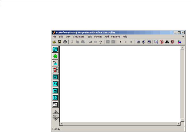
1 Double-click the Air Controller block in the Simulink model Stage1Interface to open the Stateflow chart.
3-9
3 Defining the Interface to the Simulink® Model
The Stateflow Editor opens on your desktop:
2Add a data element to hold the value of the temperature input from the Simulink model:
a From the Add menu, select Data > Input from Simulink.
3-10

Implementing the Interface
The Data properties dialog box opens on your desktop with the General tab selected:
The default values in the dialog box depend on the scope — in this case, a data input.
b In the Name field, change the name of the data element to temp.
3-11

3 Defining the Interface to the Simulink® Model
cLeave the other fields at their default values in the General tab because they meet the design requirements:
|
Field |
Default Value |
What It Means |
|
|
Scope |
Input |
Input from Simulink model. The |
|
|
|
|
data element gets its value from |
|
|
|
|
the Simulink signal on the same |
|
|
|
|
input port. |
|
|
Size |
-1 |
The data element inherits its size |
|
|
|
|
from the Simulink signal on the |
|
|
|
|
same port. |
|
|
Complexity |
Off |
The data element does not contain |
|
|
|
|
any complex values. |
|
|
Type |
Inherit: Same as |
The data element inherits its data |
|
|
|
Simulink |
type from the Simulink signal on |
|
|
|
|
the same output port. |
|
Note Ports are assigned to inputs and outputs in the order they are created. Because temp is the first input you created, it is assigned to input port 1.
dClick the Value Attributes tab and select the Watch in debugger check box.
Enabling Watch in debugger lets you examine the value of temp during breakpoints in simulation. You will try this in Chapter 8, “Simulating the Chart”.
eClick OK to apply the changes and close the dialog box.
3Add a data element to hold the value of the airflow output from the Air Controller chart:
a From the Add menu, select Data > Output to Simulink.
3-12

Implementing the Interface
The Data properties dialog box opens on your desktop, this time with different default values, associated with the scope Output:
Note Because airflow is the first output you created, it is assigned to output port 1.
bIn the Name field of the Data properties dialog box, change the name of the data element to airflow.
cIn the Type field, select uint8 (8-bit unsigned integer) from the submenu.
dClick the Value Attributes tab and look at the Initial value field.
The initial value is a blank expression, which indicates a default value of zero, based on the data type. This value is consistent with the model design, which specifies that no fans are running when the chart wakes up for the first time.
3-13

3 Defining the Interface to the Simulink® Model
e Make the following changes in the Value Attributes tab:
|
Property |
What to Specify |
|
|
Limit range |
Enter 0 for Minimum and 2 for Maximum. |
|
|
Watch in |
Select the check box to enable this option. |
|
|
debugger |
|
|
f Click OK to apply the changes and close the dialog box.
4Go back to the Simulink model by clicking the up-arrow button in the Stateflow Editor toolbar:
3-14

Implementing the Interface
Notice that the input temp and output airflow have been added to the Stateflow block:
Tip You might need to enlarge the Air Controller block to see the input and output clearly. To change the size of the block:
aSelect the block and move your pointer over one of the corners until it changes to this shape:
bHold down the left mouse button and drag the block to the desired size.
5 Save Stage1Interface.
3-15

3 Defining the Interface to the Simulink® Model
Tip There are several ways to add data objects to Stateflow charts. You used the Stateflow Editor, which lets you add data elements to the Stateflow chart that is open and has focus. However, to add data objects not just to a chart, but anywhere in the Stateflow design hierarchy, you can use a tool called the Model Explorer. This tool also lets you view and modify the data objects you have already added to a chart. For more information, see “Stateflow Hierarchy of Objects” and “Adding Data Using the Model Explorer” in the Stateflow User’s Guide. You can also add data objects programmatically using the Stateflow API, as described in “Creating Stateflow Objects” in the Stateflow API Guide.
Connecting the Stateflow Block to the Simulink Subsystem
Now that you have defined the inputs and outputs for the Stateflow Air Controller block, you need to connect them to the corresponding signals of the Simulink Physical Plant subsystem. Follow these steps:
1In the model Stage1Interface, connect the output airflow from Air Controller to the corresponding input in Physical Plant:
aPlace your pointer over the output port for airflow on the right side of the Air Controller block.
The pointer changes in shape to crosshairs.
bHold down the left mouse button and move the pointer to the input port for airflow on the left side of the Physical Plant block.
cRelease the mouse.
3-16