

Материалы к лабораторным работам / Даташиты / Разъемы TE Connectivity
.pdfAMPMODU Interconnection System
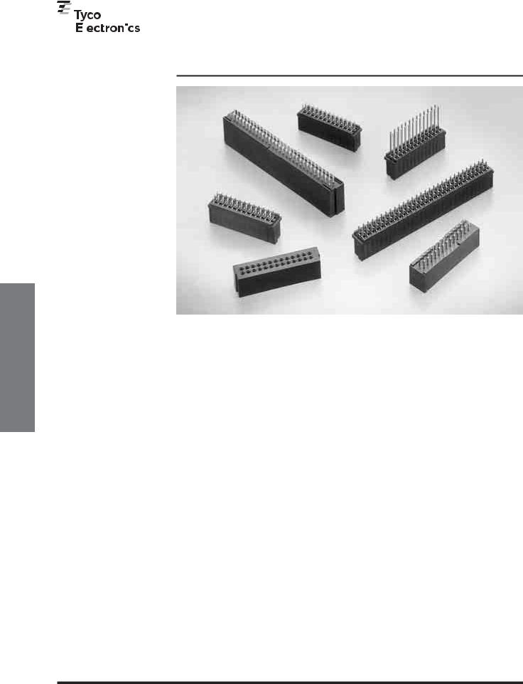
ACTION PIN Headers—Shrouded and Unshrouded
Product Facts
■Straight posted unshrouded and shrouded versions
■.025 [0.64] square ACTION PIN posts
■ACTION PIN posts make a gas-tight, press-fit connection in plated-through holes
■Designed not to damage plated-through holes
■Unshrouded headers available in selected sizes 1 through 40 positions (single-row) and 4 through 80 positions (double-row)
■Shrouded headers (doublerow) available in selected sizes of 6 through 60 positions
■Flame retardant, black thermoplastic housings, 94V-0 rated
■.100 [2.54] Centerline spacing
■Recognized under the
Component Program of
Underwriters
Laboratories Inc.,
R
File No. E28476
■ Certified by Canadian
Standards
Association, 
 R File No. LR 16455
145
Catalog 1307819 |
Dimensions are in inches and |
Dimensions are shown for |
USA: 1-800-522-6752 |
South America: 55-11-2103-6000 |
Revised 8-08 |
millimeters unless otherwise |
reference purposes only. |
Canada: 1-905-470-4425 |
Hong Kong: 852-2735-1628 |
|
specified. Values in brackets |
Specifications subject |
Mexico: 01-800-733-8926 |
Japan: 81-44-844-8013 |
www.tycoelectronics.com |
are metric equivalents. |
to change. |
C. America: 52-55-1106-0803 |
UK: 44-8706-080-208 |
Headers PIN ACTION
5
Unshrouded
ACTION PIN Headers,
5
AMPMODU Interconnection System
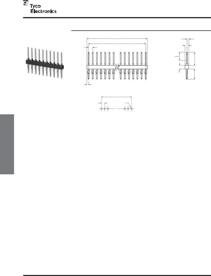
ACTION PIN Headers—Unshrouded, Single-Row,
.100 [2.54] Centerline
.025 [0.64] Square |
|
|
|
|
|
|
|
|
|
|
|
|
|
|
|
|
|
|
|
|
|
|
|
|
.050 |
|
|
|
|
|
|
|
|
|
|
|
|
|
|
|
|
|
|
|
|
|
|
|
|
|
|
|
|
||||
Straight Post |
|
|
|
|
|
|
|
A |
|
|
|
|
|
|
|
|
|
|
|
|
[1.27] |
|
|
|||||
|
|
|
|
|
|
|
|
|
|
|
|
|
|
|
|
|
|
|
|
|
|
|
|
Max. |
|
|
||
|
|
|
|
|
|
|
|
B |
|
|
|
|
|
|
|
|
|
|
|
|
|
|
|
|
|
|
||
|
|
|
|
|
|
|
|
|
|
|
|
|
|
|
|
|
.092 |
|
|
|
|
|
|
|
|
|||
|
|
|
.100 |
|
|
|
|
|
|
|
|
|
|
|
|
|
|
|
|
|
|
|
|
|||||
|
|
|
|
|
|
|
|
|
|
|
|
|
|
|
|
|
[2.34] |
|
|
|
|
|
|
|
|
|||
|
|
|
[2.54] Typ. |
|
|
|
|
|
|
|
|
|
|
|
|
|
|
|
|
|
|
|
||||||
|
|
|
|
|
|
|
|
|
|
|
|
|
|
|
|
|
|
|
|
|
|
|
|
|
|
|||
|
|
|
|
|
|
|
|
|
|
|
|
|
|
|
|
|
|
|
|
|
|
|
|
|
|
|
|
|
|
|
|
|
|
|
|
|
|
|
|
|
|
|
.200 |
|
|
|
|
|
|
|
|
|
|
|
|
||
|
|
|
|
|
|
|
|
|
|
|
|
|
|
|
|
[5.08] Ref. |
|
|
|
|
|
|
|
|
|
|
|
|
|
|
|
|
|
|
|
|
|
|
|
|
|
|
|
|
|
|
|
|
|
|
.320 |
|
|
|
|||
|
|
|
|
|
|
|
|
|
|
|
|
|
|
|
|
(Contact Area) |
|
|
|
|
|
|
|
|
||||
|
|
|
|
|
|
|
|
|
|
|
|
|
|
|
|
|
|
|
|
|
|
[8.13] |
|
|
|
|||
|
|
|
|
|
|
|
|
|
|
|
|
|
|
|
|
|
|
|
|
|
|
|
|
|
|
|||
|
|
|
|
|
|
|
|
|
|
|
|
|
|
|
|
|
|
|
|
|
|
|
|
|
|
|
||
|
|
|
|
|
|
|
|
|
|
|
|
|
|
|
|
|
|
|
|
|
|
|
|
|
|
|||
|
|
|
|
|
|
|
|
|
|
|
|
|
|
.090 |
|
|
|
|
|
|
|
|
|
|||||
|
|
|
|
|
|
|
|
|
|
|
|
|
|
|
|
[2.29] |
|
|
|
.250 |
|
|
|
|||||
|
|
|
|
|
|
|
|
|
|
|
|
|
|
|
|
|
|
|
|
|
|
|
[6.35] |
|
|
|
||
|
|
|
|
|
|
|
|
|
|
|
|
|
|
|
|
|
|
|
|
|
|
|
|
|
|
|
|
|
Material and Finish |
|
.042 |
|
|
|
|
|
|
|
|
|
|
|
|
|
|
|
|
|
|
|
|
|
|
|
|
|
|
|
[1.07] |
|
|
|
|
|
|
|
|
|
|
|
|
|
|
|
|
|
|
|
|
|
|
|
|
|
||
Housing — Black thermoplastic, 94V-0 |
|
Typ. |
|
|
|
|
|
|
|
|
|
|
|
|
|
|
|
|
|
|
|
|
|
|
|
|
|
|
|
|
|
|
|
|
|
|
|
|
|
|
|
|
|
|
|
|
|
|
|
|
|
|
|
|
|
|
|
rated |
|
|
|
|
|
|
|
|
|
|
|
|
|
|
|
|
|
|
|
|
|
|
|
|
|
|
|
|
Posts — Copper alloy, duplex plated |
|
|
|
|
|
|
|
|
|
|
|
|
|
|
|
|
|
|
|
|
|
|
|
|
|
|
||
|
|
|
|
|
|
|
B |
|
|
|
|
|
|
|
|
|
|
|
|
|
|
|
|
|||||
|
|
|
|
|
|
|
|
|
|
|
|
|
|
|
|
|
|
|
|
|
|
|
|
|||||
.000030 [0.00076] gold on contact area, |
|
|
|
|
|
See page 168 for |
|
|
Recommended PC Board Hole Layout |
|||||||||||||||||||
|
.100* |
|
|
|||||||||||||||||||||||||
.000100-.000200 [0.00254-0.00508] |
|
[2.54] |
|
|
hole dimensions |
|
|
*±.003 [±0.08] tolerances not to accumulate |
||||||||||||||||||||
|
|
|
|
|
|
|
|
|
|
|
||||||||||||||||||
matte tin on termination end, with entire |
|
|
|
|
|
|
|
|
|
|
|
|
|
within one connector pattern. |
|
|
|
|
|
|
|
|||||||
post underplated .000050 [0.00127] |
|
|
|
|
|
|
|
|
|
|
|
|
|
|
|
|
|
|
|
|
|
|
|
|
|
|
|
|
nickel |
|
|
|
|
|
|
|
|
|
|
|
|
|
|
|
|
|
|
|
|
|
|
|
|
|
|
|
|
|
|
|
|
|
|
|
|
|
|
|
|
|
|
|
|
|
|
|
|
|
|
|
|
|
|
|
||
Related Product Data |
|
|
|
|
|
|
|
|
|
|
|
|
|
|
|
|
|
|
Part Nos. |
|
|
|
|
|
|
|
||
No. of |
|
|
|
|
Dimensions |
|
|
|
For .062 |
|
For .093-.125 |
|||||||||||||||||
Mateable Connectors — |
Pos. |
|
|
|
A |
|
|
|
|
|
|
B |
[1.57] |
|
|
|
|
|
[.236-3.18] |
|
||||||||
Refer to the Mating Post Selection |
|
|
|
|
|
|
|
|
|
|
|
|
|
Thick PC Boards |
Thick PC Boards |
|||||||||||||
Guide — page 90 |
1 |
.084 |
[2.13] |
|
|
|
|
|
|
— |
8-103336-5 |
|
|
|
|
8-102898-5 |
|
|||||||||||
ACTION PIN Posts — pages 150, 151 |
2 |
.184 |
[4.67] |
.100 |
[2.54] |
8-103336-4 |
|
|
|
|
8-102898-4 |
|
||||||||||||||||
Application Tooling — page 152 |
3 |
.284 |
[7.21] |
.200 |
[5.08] |
9-103336-0 |
|
|
|
|
9-102898-0 |
|
||||||||||||||||
4 |
.384 |
[9.75] |
.300 |
[7.62] |
8-103336-6 |
|
|
|
|
8-102898-6 |
|
|||||||||||||||||
|
|
|
|
|
|
|||||||||||||||||||||||
|
|
|
|
|
|
|
|
|
|
|
|
|
|
|
||||||||||||||
|
5 |
.484 |
[12.29] |
.400 |
[10.16] |
8-103336-8 |
|
|
|
|
8-102898-8 |
|
||||||||||||||||
Technical Documents — page 276 |
|
|
|
|
|
|
|
|
|
|
|
|
|
|
||||||||||||||
6 |
.584 |
[14.83] |
.500 |
[12.70] |
8-103336-7 |
|
|
|
|
8-102898-7 |
|
|||||||||||||||||
See mating connector for applicable |
7 |
.684 |
[17.37] |
.600 |
[15.24] |
8-103336-9 |
|
|
|
|
8-102898-9 |
|
||||||||||||||||
|
|
|
|
|
|
|
|
|
|
|
|
|
|
|
|
|
|
|
|
|
|
|
|
|
|
|
|
|
8 |
.784 |
[19.91] |
.700 |
[17.78] |
5-103336-1 |
|
|
|
|
5-102898-1 |
|
|||||||||||||||||
product and application specifications |
|
|
|
|
|
|||||||||||||||||||||||
|
9 |
.884 |
[22.45] |
.800 |
[20.32] |
5-103336-2 |
|
|
|
|
5-102898-2 |
|
||||||||||||||||
|
10 |
.984 |
[24.99] |
.900 |
[22.86] |
5-103336-3 |
|
|
|
|
5-102898-3 |
|
||||||||||||||||
|
|
|
|
|
|
|
|
|
|
|
|
|
|
|
||||||||||||||
|
11 |
1.084 |
[27.53] |
1.000 |
[25.40] |
5-103336-4 |
|
|
|
|
5-102898-4 |
|
||||||||||||||||
|
|
|
|
|
|
|
|
|
|
|
|
|
|
|
||||||||||||||
|
12 |
1.184 |
[30.07] |
1.100 |
[27.94] |
5-103336-5 |
|
|
|
|
5-102898-5 |
|
||||||||||||||||
|
13 |
1.284 |
[32.61] |
1.200 |
[30.48] |
5-103336-6 |
|
|
|
|
5-102898-6 |
|
||||||||||||||||
|
|
|
|
|
|
|
|
|
|
|
|
|
|
|
||||||||||||||
|
14 |
1.384 |
[35.15] |
1.300 |
[33.02] |
5-103336-7 |
|
|
|
|
5-102898-7 |
|
||||||||||||||||
|
|
|
|
|
|
|
|
|
|
|
|
|
|
|
||||||||||||||
|
15 |
1.484 |
[37.69] |
1.400 |
[35.56] |
5-103336-8 |
|
|
|
|
5-102898-8 |
|
||||||||||||||||
|
16 |
1.584 |
[40.23] |
1.500 |
[38.10] |
5-103336-9 |
|
|
|
|
5-102898-9 |
|
||||||||||||||||
|
|
|
|
|
|
|
|
|
|
|
|
|
|
|
||||||||||||||
|
17 |
1.684 |
[42.77] |
1.600 |
[40.64] |
6-103336-0 |
|
|
|
|
6-102898-0 |
|
||||||||||||||||
|
|
|
|
|
|
|
|
|
|
|
|
|
|
|
||||||||||||||
|
18 |
1.784 |
[45.31] |
1.700 |
[43.18] |
6-103336-1 |
|
|
|
|
6-102898-1 |
|
||||||||||||||||
|
19 |
1.884 |
[47.85] |
1.800 |
[45.72] |
6-103336-2 |
|
|
|
|
6-102898-2 |
|
||||||||||||||||
|
|
|
|
|
|
|
|
|
|
|
|
|
|
|
||||||||||||||
|
20 |
1.984 |
[50.39] |
1.900 |
[48.26] |
6-103336-3 |
|
|
|
|
6-102898-3 |
|
||||||||||||||||
|
|
|
|
|
|
|
|
|
|
|||||||||||||||||||
|
21 |
2.084 [52.93] |
2.000 [50.80] |
|
|
— |
6-102898-4 |
|
||||||||||||||||||||
|
22 |
2.184 [55.47] |
2.100 [53.34] |
|
|
— |
6-102898-5 |
|
||||||||||||||||||||
|
|
|
|
|
|
|
|
|
|
|||||||||||||||||||
|
23 |
2.284 [58.01] |
2.200 [55.88] |
|
|
— |
6-102898-6 |
|
||||||||||||||||||||
|
|
|
|
|
|
|
|
|
|
|||||||||||||||||||
|
24 |
2.384 [60.55] |
2.300 [58.42] |
|
|
— |
6-102898-7 |
|
||||||||||||||||||||
|
25 |
2.484 [63.09] |
2.400 [60.96] |
6-103336-8 |
|
|
|
|
6-102898-8 |
|
||||||||||||||||||
|
|
|
|
|
|
|
|
|
|
|||||||||||||||||||
|
26 |
2.584 [65.63] |
2.500 [63.50] |
|
|
— |
6-102898-9 |
|
||||||||||||||||||||
|
|
|
|
|
|
|
|
|
|
|||||||||||||||||||
|
27 |
2.684 [68.17] |
2.600 [66.04] |
|
|
— |
7-102898-0 |
|
||||||||||||||||||||
|
28 |
2.784 [70.71] |
2.700 [68.58] |
|
|
— |
7-102898-1 |
|
||||||||||||||||||||
|
|
|
|
|
|
|
|
|
|
|||||||||||||||||||
|
29 |
2.884 [73.25] |
2.800 [71.12] |
|
|
— |
7-102898-2 |
|
||||||||||||||||||||
|
|
|
|
|
|
|
|
|
|
|
|
|
||||||||||||||||
|
30 |
2.984 [75.79] |
2.900 [73.66] |
7-103336-3 |
|
|
|
|
7-102898-3 |
|
||||||||||||||||||
|
32 |
3.184 [80.87] |
3.100 [78.74] |
7-103336-5 |
|
|
|
|
7-102898-5 |
|
||||||||||||||||||
|
|
|
|
|
|
|
|
|
|
|
|
|
||||||||||||||||
|
36 |
3.584 [91.03] |
3.500 [88.90] |
7-103336-9 |
|
|
|
|
7-102898-9 |
|
||||||||||||||||||
|
|
|
|
|
|
|
|
|
|
|
|
|
||||||||||||||||
|
40 |
3.984 [101.19] |
3.900 [99.06] |
8-103336-3 |
|
|
|
|
8-102898-3 |
|
||||||||||||||||||
|
|
|
|
|
|
|
|
|
|
|
|
|
|
|
|
|
|
|
|
|
|
|
|
|
|
|
|
|
Note: To insert header into PC board, use seating tool with arbor tool or air powered machine—page 152.
Note: All part numbers are RoHS compliant.
146
Catalog 1307819 |
Dimensions are in inches and |
Dimensions are shown for |
USA: 1-800-522-6752 |
South America: 55-11-2103-6000 |
Revised 8-08 |
millimeters unless otherwise |
reference purposes only. |
Canada: 1-905-470-4425 |
Hong Kong: 852-2735-1628 |
|
specified. Values in brackets |
Specifications subject |
Mexico: 01-800-733-8926 |
Japan: 81-44-844-8013 |
www.tycoelectronics.com |
are metric equivalents. |
to change. |
C. America: 52-55-1106-0803 |
UK: 44-8706-080-208 |
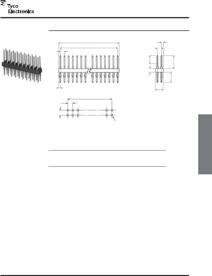
AMPMODU Interconnection System
ACTION PIN Headers—Unshrouded, Double-Row,
.100 x .100 [2.54 x 2.54] Centerline
.025 [0.64] Square
Straight Post
Material and Finish
Housing — Black thermoplastic, 94V-0 rated
Posts — Copper alloy, duplex plated
.000030 [0.00076] gold on contact area,
.000100-.000200 [0.00254-0.00508] matte tin on termination end, with entire post underplated .000050 [0.00127] nickel
Related Product Data
Mateable Connectors —
Refer to the Mating Post Selection Guide — page 90
ACTION PIN Posts — pages 150, 151 Application Tooling — page 152
Accessories
|
|
|
|
|
|
|
|
|
|
|
|
|
|
|
|
|
|
|
|
|
.050 |
|
|
|
|
|
|
|
|
|
|
|
|
|
|
|
|
|
|
|
|
|
|
|
|
|
|
|
|
[1.27] |
|
|
|
|
|
|
|
|
|
|
|
|
|
|
|
|
|
|
|
A |
|
|
|
|
|
|
||||||||||
|
|
|
|
|
|
|
|
|
|
|
|
|
|
|
|
|
|
|
|
Max. |
|
|
|
|
|
|
|
|
|
|
|
|
|
|
|
|
|
|
|
|
|
|
|
|
|
|
|
|
|
|
|||||||
|
|
|
|
|
|
|
|
|
|
|
|
|
|
|
|
|
|
|
|
|
|
|
|
.100 |
|
|
|
|
|
|
|
|
|
|
|
|
|
|
|
|
|
|
|
|
|
|
|
|
|
|
|
|
|
|
|
||
|
|
|
|
|
|
|
|
|
|
|
B |
|
|
|
|
|
|
|||||||||||
|
|
|
|
|
|
|
|
|
|
|
|
|
|
|
|
|
|
|
|
|
|
[2.54] |
|
|
||||
|
|
|
|
|
.100 |
Typ. |
|
|
|
|
|
|
|
|
|
|
|
|
|
|
|
|
|
|||||
|
|
|
|
|
|
|
|
|
|
|||||||||||||||||||
|
|
|
|
|
[2.54] |
|
|
|
|
|
|
|
|
|
|
|
|
|
|
|||||||||
|
|
|
|
|
|
|
.200 |
Ref. |
|
|
|
|
|
|
|
|
|
|
||||||||||
|
|
|
|
|
|
|
[5.08] |
|
|
|
|
|
|
|
|
|
|
|||||||||||
|
|
|
|
|
|
|
.320 |
|||||||||||||||||||||
|
|
|
|
|
|
|
|
|
|
|
|
|
|
|
|
|
||||||||||||
|
|
|
|
|
|
|
|
|
|
|
|
|
|
|
(Contact Area) |
|
|
|
|
|
|
|
[8.13] |
|||||
|
|
|
|
|
|
|
|
|
|
|
|
|
|
|
|
|
|
|
|
|
|
|
|
|
|
|||
|
|
|
|
|
|
|
|
|
|
|
|
|
|
|
|
|
|
|
|
|
|
|
|
|
|
|
|
|
|
|
|
|
|
|
|
|
|
|
|
|
|
|
|
|
.090 |
|
|
|
|
|
|
|
|
|
|
||
|
|
|
|
|
|
|
|
|
|
|
|
|
|
|
|
|
[2.29] |
|
|
|
|
|
|
.250 |
|
|||
|
|
|
|
|
|
|
|
|
|
|
|
|
|
|
|
|
|
|
|
|
|
|
|
|
[6.35] |
|
||
|
|
|
|
|
|
|
|
|
|
|
|
|
|
|
|
|
|
|
|
|
|
|
|
|
|
|
|
|
.042 |
|
|
|
|
|
|
|
|
|
|
|
|
|
|
|
|
|
|
|
|
|
|
|
|
|
|
|
|
[1.07] |
|
|
|
|
|
|
|
|
|
|
|
|
|
|
|
|
|
|
|
|
|
|
|
|
|
|||
|
|
|
|
|
|
|
|
|
|
|
|
|
|
|
|
|
|
.192 |
|
|||||||||
(2 Plc.) |
|
|
|
|
|
|
|
|
|
|
|
|
|
|
|
|
|
|
|
|
|
|
|
|
[4.88] |
|
||
|
|
|
|
|
|
|
|
|
|
|
|
|
|
|
|
|
|
|
|
|
|
|
|
|
|
|
|
|
|
|
|
|
|
|
|
|
|
|
|
|
B |
|
|
|
|
|
|
|
|
|
|
|
|
|
|||
|
|
.100* |
|
|
|
|
.100* |
|
|
|
|
|
|
|
|
|
|
|
|
|
|
|
|
|
|
|
||
|
|
|
|
|
|
|
|
|
|
|
|
|
|
|
|
|
|
|
|
|
|
|
|
|
|
|||
|
|
[2.54] |
|
|
|
|
[2.54] |
|
|
|
|
|
|
|
|
|
|
|
|
|
|
|
|
|
|
|
||
|
|
|
|
|
|
|
|
|
|
|
|
|
|
|
|
|
|
|
|
|
|
|
|
|
|
|
|
|
|
|
|
|
|
|
|
|
|
|
|
|
|
|
|
|
|
|
|
|
|
|
|
|
|
|
|
|
|
|
|
|
|
|
|
|
|
|
|
|
|
|
|
|
See page 151 for |
|
|
|
|
|
|
|
|
|
|
|
|
|
|
|
|
|
|
|
|
|
|
|
|
|
|
|
|
hole dimensions |
|
|
|
|
|
|
|
|
|
|
|
|
|
|
|
|
|
|
|
|
|
|
|
|
|
|
|
|
|
|
|
|
|
|
|
|
|
|
|
|
|
|
Recommended PC Board Hole Layout
*±.003 [±0.08] tolerances not to accumulate within one connector pattern.
|
|
|
|
Part Nos. |
|
No. of |
|
Dimensions |
|
For .062 [1.57] |
For .093-.125 |
Pos. |
A |
B |
|
[.236-3.18] |
|
|
Thick |
||||
|
|
|
|
PC Boards |
Thick |
|
|
|
|
PC Boards |
|
|
|
|
|
|
Barrier Insert — page 204
Technical Documents — page 276
See mating connector for applicable product and application specifications
4 |
.184 |
[4.67] |
.100 |
[2.54] |
5-103542-1 |
5-103233-1 |
6 |
.284 |
[7.21] |
.200 |
[5.08] |
5-103542-2 |
5-103233-2 |
8 |
.384 |
[9.75] |
.300 |
[7.62] |
5-103542-3 |
5-103233-3 |
10 |
.484 |
[12.29] |
.400 |
[10.16] |
5-103542-4 |
5-103233-4 |
12 |
.584 |
[14.83] |
.500 |
[12.70] |
5-103542-5 |
5-103233-5 |
14 |
.684 |
[17.37] |
.600 |
[15.24] |
5-103542-6 |
5-103233-6 |
16 |
.784 |
[19.91] |
.700 |
[17.78] |
5-103542-7 |
5-103233-7 |
18 |
.884 |
[22.45] |
.800 |
[20.32] |
5-103542-8 |
5-103233-8 |
20 |
.984 |
[24.99] |
.900 |
[22.86] |
5-103542-9 |
5-103233-9 |
22 |
1.084 |
[27.53] |
1.000 |
[25.40] |
6-103542-0 |
6-103233-0 |
24 |
1.184 |
[30.07] |
1.100 |
[27.94] |
6-103542-1 |
6-103233-1 |
26 |
1.284 |
[32.61] |
1.200 |
[30.48] |
6-103542-2 |
6-103233-2 |
28 |
1.384 |
[35.15] |
1.300 |
[33.02] |
6-103542-3 |
6-103233-3 |
30 |
1.484 |
[37.69] |
1.400 |
[35.56] |
6-103542-4 |
6-103233-4 |
32 |
1.584 |
[40.23] |
1.500 |
[38.10] |
6-103542-5 |
6-103233-5 |
34 |
1.684 |
[42.77] |
1.600 |
[40.64] |
6-103542-6 |
6-103233-6 |
36 |
1.784 |
[45.31] |
1.700 |
[43.18] |
6-103542-7 |
6-103233-7 |
38 |
1.884 |
[47.85] |
1.800 |
[45.72] |
6-103542-8 |
6-103233-8 |
40 |
1.984 |
[50.39] |
1.900 |
[48.26] |
6-103542-9 |
6-103233-9 |
42 |
2.084 |
[52.39] |
2.000 |
[50.80] |
7-103542-0 |
7-103233-0 |
46 |
2.284 |
[58.01] |
2.200 |
[55.88] |
7-103542-2 |
— |
50 |
2.484 |
[63.09] |
2.400 |
[60.96] |
7-103542-4 |
7-103233-4 |
60 |
2.984 |
[75.79] |
2.900 |
[73.66] |
7-103542-9 |
7-103233-9 |
66 |
3.284 |
[83.41] |
3.200 |
[81.28] |
8-103542-2 |
— |
80 |
3.984 |
[101.19] |
3.900 |
[99.06] |
8-103542-9 |
8-103233-9 |
Note: All part numbers are RoHS compliant.
147
Catalog 1307819 |
Dimensions are in inches and |
Dimensions are shown for |
USA: 1-800-522-6752 |
South America: 55-11-2103-6000 |
Revised 8-08 |
millimeters unless otherwise |
reference purposes only. |
Canada: 1-905-470-4425 |
Hong Kong: 852-2735-1628 |
|
specified. Values in brackets |
Specifications subject |
Mexico: 01-800-733-8926 |
Japan: 81-44-844-8013 |
www.tycoelectronics.com |
are metric equivalents. |
to change. |
C. America: 52-55-1106-0803 |
UK: 44-8706-080-208 |
Headers, PIN ACTION
Unshrouded
5
Shrouded
ACTION PIN Headers,
5
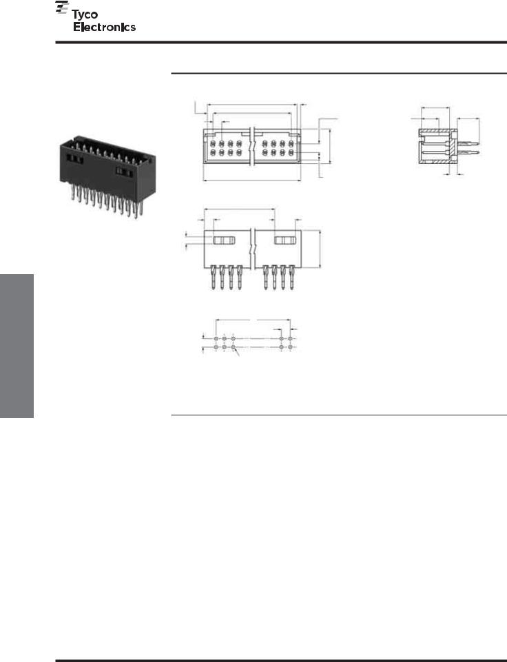
AMPMODU Interconnection System
ACTION PIN Headers—Shrouded with .066 [1.68] End Dimension, Double-Row, .100 x .100 [2.54 x 2.54] Centerline
.025 [0.64] Square Straight Post (with Detent Windows, for .093-.125
[.236-3.18] Thick PC Board)
Material and Finish
Housing — Black thermoplastic, 94V-0 rated
Posts — Copper alloy, duplex plated
.000030 [0.00076] gold on contact area,
.000100-.000200 [0.00254-0.00508] matte tin on termination end, with entire post underplated .000050 [0.00127] nickel
Related Product Data
Mateable Connectors —
AMPMODU Board Mount Receptacles — pages 176, 179, 180
AMPMODU Wire-Applied Receptacles — pages 217-219
AMPMODU MT Receptacles — pages 256, 257
ACTION PIN Posts — pages 150, 151 Application Tooling — page 152
Accessories
Barrier Insert — page 204
Technical Documents — page 276
See mating connector for applicable product and application specifications
|
|
.066 |
|
|
|
|
|
|
|
|
|
|
|
|
|
|
|
|
|
|
|
|
|
|
|
|
|
|
|
|
|
[1.68] |
|
|
|
|
|
|
|
|
|
|
|
|
|
|
|
|
|
|
|
|
|
|
|
|
|
|
|
|
(2 Plc.) |
|
|
|
|
|
|
|
|
|
.040 |
|
|
|
|
|
|
|
|
|
|
|
|
||||||
|
|
|
|
|
|
|
|
|
|
B |
|
|
[1.02] |
|
|
|
|
|
|
.320 |
|
|
|
|
|||||
|
|
|
|
|
|
|
|
|
|
|
|
||||||||||||||||||
|
|
|
|
|
|
|
|
|
|
|
|
|
|
(3 Plc.) |
|
|
|
.200 |
|
[8.13] |
|
|
|
|
|||||
|
|
|
|
|
|
|
|
|
|
C |
|
|
|
|
|
|
|||||||||||||
|
|
|
|
|
|
|
|
|
|
|
.250 |
|
|||||||||||||||||
|
|
|
|
|
|
|
|
|
|
|
.100 |
Ref. |
|
|
|||||||||||||||
|
|
|
|
|
|
|
|
|
|
|
|
|
|
|
|
|
|
|
[5.08] |
|
|
|
|||||||
|
|
|
|
|
|
|
|
|
|
|
|
|
|
|
|||||||||||||||
.100 |
|
Typ. |
|
|
|
|
|
|
|
|
|
|
|
|
|||||||||||||||
|
|
|
|
|
|
|
|
|
|
|
|
|
[2.54] |
|
|
|
[6.35] |
|
|||||||||||
[2.54] |
|
|
|
|
|
|
|
|
|
|
|
|
|
|
|
|
|
|
|
|
(Contact Area) |
|
|
|
|
|
|||
|
|
|
|
|
|
|
|
|
|
|
|
|
|
|
|
|
|
|
|
|
|
|
|
|
|||||
|
|
|
|
|
|
|
|
|
|
|
|
|
|
|
|
|
|
|
|
|
|
|
|
|
|
|
|
|
|
|
|
|
|
|
|
|
|
|
|
|
|
|
|
|
|
|
|
|
|
|
|
|
|
|
|||||
|
|
|
|
|
|
|
|
|
|
|
|
.400 |
|
|
|
|
|
|
|
|
|
||||||||
|
|
|
|
|
|
|
|
|
|
|
|
|
|
|
[10.16] |
|
|
|
|
|
|
|
|
|
|||||
|
|
|
|
|
|
|
|
|
|
|
|
|
|
|
|
|
|
|
|
|
|
|
|
|
|
|
|
|
|
|
|
|
|
|
|
|
|
|
|
|
|
.090 |
|
|
|
|
|
.090 |
|||||||||||
|
|
|
|
|
|
|
|
|
|
|
|
|
|
|
|
|
[2.29] |
|
|
|
|
[2.29] |
|||||||
|
|
|
|
|
|
|
|
|
|
A |
|
|
|
||||||||||||||||
|
|
|
|
|
|
|
|
|
|
|
|
|
|
|
|
|
(2 Plc.) |
|
|
|
|
|
|
|
|
||||
|
|
|
|
|
|
|
|
|
|
|
|
|
|
|
|
|
|
|
|
|
|
|
|
|
|
||||
|
|
|
|
|
|
|
|
|
|
|
|
|
|
|
|
|
|
|
|
|
|
|
|
|
|
|
|
||
|
|
|
|
|
|
|
|
E |
|
|
|
|
|
|
|
|
|
|
|
|
|
|
|
|
|
|
|||
|
|
|
|
|
|
|
.240 |
|
|
|
|
|
|
|
|
|
|
|
|
|
|
||||||||
|
|
|
|
|
|
|
|
|
|
|
|
|
|
|
|
|
|
|
|
|
|
|
|
|
|
|
|
||
|
|
|
|
|
|
|
|
|
|
|
[6.10] |
|
|
|
|
|
|
|
|
|
|
|
|
|
|
||||
|
|
|
|
|
|
D |
|
|
|
|
|
|
|
|
|
|
|
|
|
|
|
|
|||||||
|
|
|
|
|
|
|
|
|
|
|
|
|
|
(2 Plc.) |
|
|
|
|
|
|
|
|
|
|
|
|
|
|
|
|
|
.440 |
|
|
[11.18] |
.085 |
|
|
|
|
|
[2.16] |
|
|
.100* B
[2.54] |
.100* |
|
[2.54] |
||
|
See page 151 for hole dimensions
Recommended PC Board Hole Layout
*±.003 [±0.08] tolerances not to accumulate within one connector pattern.
No. of |
|
|
|
|
Dimensions |
|
|
|
|
Header |
|
Pos. |
|
A |
|
B |
|
C |
|
D |
|
E |
Part Nos. |
6 |
.412 |
[10.46] |
.332 |
[8.43] |
.200 |
[5.08] |
.106 |
[2.69] |
— |
5-102699-2 |
|
8 |
.512 |
[13.00] |
.432 |
[10.97] |
.300 |
[7.62] |
.106 |
[2.69] |
— |
5-102699-3 |
|
10 |
.612 |
[15.54] |
.532 |
[13.51] |
.400 |
[10.16] |
.206 |
[5.23] |
— |
5-102699-4 |
|
12 |
.712 |
[18.08] |
.632 |
[16.05] |
.500 |
[12.70] |
.206 |
[5.23] |
— |
5-102699-5 |
|
14 |
.812 |
[20.62] |
.732 |
[18.59] |
.600 |
[15.24] |
.306 |
[7.77] |
— |
5-102699-6 |
|
16 |
.912 |
[23.16] |
.832 |
[21.13] |
.700 |
[17.78] |
.306 |
[7.77] |
— |
5-102699-7 |
|
18 |
1.012 |
[25.70] |
.932 |
[23.67] |
.800 |
[20.32] |
.406 |
[10.31] |
— |
5-102699-8 |
|
20 |
1.112 |
[28.24] |
1.032 |
[26.21] |
.900 |
[22.86] |
.106 |
[2.69] |
.806 |
[20.47] |
5-102699-9 |
26 |
1.412 |
[35.86] |
1.332 |
[33.83] |
1.200 |
[30.48] |
.106 |
[2.69] |
1.106 |
[28.09] |
6-102699-2 |
30 |
1.612 |
[40.94] |
1.532 |
[38.91] |
1.400 |
[35.56] |
.106 |
[2.69] |
1.306 |
[33.17] |
6-102699-4 |
34 |
1.812 |
[46.02] |
1.732 |
[43.99] |
1.600 |
[40.64] |
.106 |
[2.69] |
1.506 |
[38.25] |
6-102699-6 |
40 |
2.112 |
[53.64] |
2.032 |
[51.61] |
1.900 |
[48.26] |
.106 |
[2.69] |
1.806 |
[45.87] |
6-102699-9 |
50 |
2.612 |
[66.34] |
2.532 |
[64.31] |
2.400 |
[60.96] |
.106 |
[2.69] |
2.306 |
[58.57] |
7-102699-3 |
60 |
3.112 |
[79.04] |
3.032 |
[77.01] |
2.900 |
[73.66] |
.106 |
[2.69] |
2.806 |
[71.27] |
7-102699-8 |
Note: All part numbers are RoHS compliant.
148
Catalog 1307819 Revised 8-08
www.tycoelectronics.com
Dimensions are in inches and millimeters unless otherwise specified. Values in brackets are metric equivalents.
Dimensions are shown for |
USA: 1-800-522-6752 |
South America: 55-11-2103-6000 |
reference purposes only. |
Canada: 1-905-470-4425 |
Hong Kong: 852-2735-1628 |
Specifications subject |
Mexico: 01-800-733-8926 |
Japan: 81-44-844-8013 |
to change. |
C. America: 52-55-1106-0803 |
UK: 44-8706-080-208 |
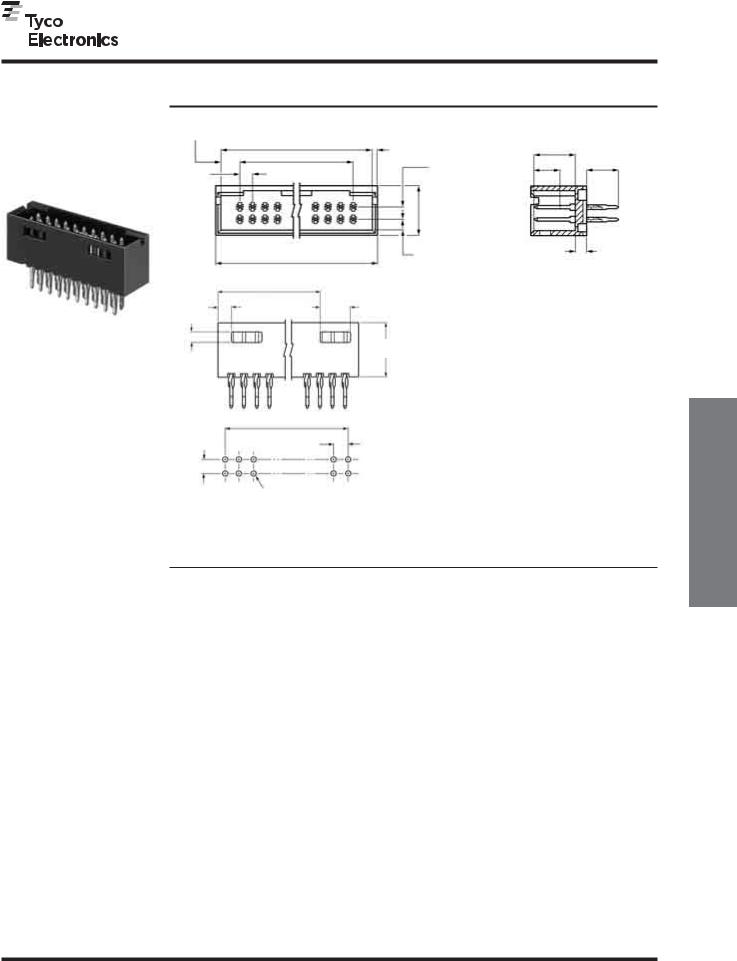
AMPMODU Interconnection System
ACTION PIN Headers—Shrouded with .150 [3.81] End Dimension, Double-Row, .100 x .100 [2.54 x 2.54] Centerline
.025 [0.64] Square Straight Post (with Detent Windows, for .093-.125
[.236-3.18] Thick PC Board)
Material and Finish
Housing — Black thermoplastic, 94V-0 rated
Posts — Copper alloy, duplex plated
.000030 [0.00076] gold on contact area,
.000100-.000200 [0.00254-0.00508] matte tin on termination end, with entire post underplated .000050 [0.00127] nickel
Related Product Data
Mateable Connectors —
AMPMODU MTE Receptacles — pages 232, 233
ACTION PIN Posts — pages 150, 151 Application Tooling — page 152
Accessories
Barrier Insert — page 204
Technical Documents — page 276
See mating connector for applicable product and application specifications
|
|
.150 |
|
|
|
|
|
|
|
|
|
|
|
|
|
|
|
|
|
|
|
|
|
|
|
|
|
|
|
|
|
|
|
[3.81] |
|
|
|
|
|
|
|
|
|
|
|
|
|
|
|
|
|
|
|
|
|
|
|
|
|
|
|
|
|
||
|
|
|
|
|
|
|
|
|
|
|
|
.040 |
|
|
|
|
|
|
|
|
|
|
|
|
|
|
|
|
||||
|
(2 Plc.) |
|
|
|
|
|
|
|
|
|
|
|
|
|
|
|
|
|
|
|
|
|
|
|
|
|
|
|
||||
|
|
|
|
|
|
|
|
|
|
|
|
|
|
|
|
|
|
|
.250 |
|
||||||||||||
|
|
|
|
|
|
|
|
|
|
|
B |
|
|
|
[1.02] |
|
|
|
|
|
|
|
|
.320 |
|
|
||||||
|
|
|
|
|
|
|
|
|
|
|
|
|
|
|
|
|
|
|
|
|
|
|
||||||||||
|
|
|
|
|
|
|
|
|
|
|
|
|
|
|
(3 Plc.) |
|
|
|
|
.200 |
|
|
|
[8.13] |
|
[6.35] |
|
|||||
|
|
|
|
|
|
|
|
|
|
|
|
|
|
|
|
|
|
|
|
|
|
|
||||||||||
|
|
|
|
|
|
|
|
|
|
|
|
|
|
|
|
.100 |
|
|
|
|
|
|
|
|
|
|||||||
|
|
|
|
|
|
|
|
|
|
|
C |
Ref. |
|
|
|
|
|
|
||||||||||||||
.100 |
|
Typ. |
|
|
|
|
|
|
|
|
|
|
|
|
|
|
|
[2.54] |
[5.08] |
|
|
|
|
|
|
|
|
|
|
|||
[2.54] |
|
|
|
|
|
|
|
|
|
|
|
|
|
|
|
|
|
|
|
(Contact Area) |
|
|
|
|
|
|||||||
|
|
|
|
|
|
|
|
|
|
|
|
|
|
|
|
|
|
|
|
|
|
|
|
|
|
|
|
|
|
|||
|
|
|
|
|
|
|
|
|
|
|
|
.400 |
|
|
|
|
|
|
|
|
|
|
|
|
|
|
||||||
|
|
|
|
|
|
|
|
|
|
|
|
|
|
|
[10.16] |
|
|
|
|
|
|
|
|
|
|
|
|
|
||||
|
|
|
|
|
|
|
|
|
|
|
|
|
|
|
|
|
|
|
|
|
|
|
|
|
|
|
|
|
|
|
|
|
|
|
|
|
|
|
|
|
|
|
|
|
|
|
|
|
|
|
.090 |
|
|
|
|
|
|
|
|
.090 |
|||||
|
|
|
|
|
|
|
|
|
|
|
|
|
|
|
|
|
|
[2.29] |
|
|
|
|
|
|
|
|
[2.29] |
|||||
|
|
|
|
|
|
|
|
|
|
|
A |
|
|
|
|
|
(2 Plc.) |
|
|
|
|
|
|
|
|
|
|
|
|
|||
|
|
|
|
|
|
|
|
|
|
|
|
|
|
|
|
|
|
|
|
|
||||||||||||
|
|
|
|
|
|
|
|
|
|
|
|
|
|
|
|
|
|
|
|
|
|
|
|
|
|
|
|
|
|
|||
|
|
|
|
|
|
|
|
|
|
|
|
|
|
|
|
|
|
|
|
|
|
|
|
|
|
|
|
|
|
|||
|
|
|
|
|
|
|
E |
|
|
|
|
|
|
|
|
|
|
|
|
|
|
|
|
|
|
|
|
|
||||
|
|
|
|
|
.240 |
|
|
|
|
|
|
|
|
|
|
|
|
|
|
|
|
|
|
|
||||||||
|
|
|
|
|
|
|
|
|
|
|
|
|
|
|
|
|
|
|
|
|
|
|
|
|
|
|
|
|
|
|
|
|
|
|
|
|
|
|
|
|
|
|
[6.10] |
|
|
|
|
|
|
|
|
|
|
|
|
|
|
|
|
|
|
|
|||
|
|
|
|
|
D |
|
|
|
|
|
|
|
|
|
|
|
|
|
|
|
|
|
|
|
|
|||||||
|
|
|
|
|
|
|
|
|
|
|
|
|
(2 Plc.) |
|
|
|
|
|
|
|
|
|
|
|
|
|
|
|
|
|
|
|
.440
[11.18]
.085
[2.16]
.100* |
|
B |
|
|
|
|
|
|
|
|
|
.100* |
||
[2.54] |
|
|
||
|
|
|
[2.54] |
|
|
|
|
||
|
|
|
|
|
See page 151 for hole dimensions
Recommended PC Board Hole Layout
*±.003 [±0.08] tolerances not to accumulate within one connector pattern.
No. of |
|
|
|
|
Dimensions |
|
|
|
|
Header |
|
Pos. |
|
A |
|
B |
|
C |
|
D |
|
E |
Part Nos. |
6 |
.580 |
[14.73] |
.500 |
[8.43] |
.200 |
[5.08] |
.190 |
[4.83] |
— |
6-102557-0 |
|
8 |
.680 |
[17.27] |
.600 |
[10.97] |
.300 |
[7.62] |
.190 |
[4.83] |
— |
6-102557-1 |
|
10 |
.780 |
[19.81] |
.700 |
[17.78] |
.400 |
[10.16] |
.290 |
[7.37] |
— |
5-102557-9 |
|
12 |
.880 |
[22.35] |
.800 |
[20.32] |
.500 |
[12.70] |
.290 |
[7.37] |
— |
6-102557-2 |
|
14 |
.980 |
[24.89] |
.900 |
[22.86] |
.600 |
[15.24] |
.390 |
[9.91] |
— |
6-102557-3 |
|
16 |
1.080 |
[27.43] |
1.000 |
[25.40] |
.700 |
[17.78] |
.390 |
[9.91] |
— |
6-102557-4 |
|
18 |
1.180 |
[29.97] |
1.100 |
[27.94] |
.800 |
[20.32] |
.490 |
[10.31] |
— |
6-102557-5 |
|
20 |
1.280 |
[32.51] |
1.200 |
[30.48] |
.900 |
[22.86] |
.190 |
[4.83] |
.890 |
[22.61] |
5-102557-2 |
24 |
1.480 |
[37.59] |
1.400 |
[35.56] |
1.100 |
[27.94] |
.190 |
[4.83] |
1.090 |
[27.69] |
6-102557-7 |
26 |
1.580 |
[40.13] |
1.500 |
[38.10] |
1.200 |
[30.48] |
.190 |
[4.83] |
1.190 |
[30.23] |
5-102557-3 |
30 |
1.780 |
[45.21] |
1.700 |
[43.18] |
1.400 |
[35.56] |
.190 |
[4.83] |
1.390 |
[35.31] |
5-102557-4 |
34 |
1.980 |
[50.29] |
1.900 |
[48.26] |
1.600 |
[40.64] |
.190 |
[4.83] |
1.590 |
[40.39] |
5-102557-5 |
40 |
2.280 |
[57.91] |
2.200 |
[55.88] |
1.900 |
[48.26] |
.190 |
[4.83] |
1.890 |
[48.01] |
5-102557-1 |
50 |
2.780 |
[70.61] |
2.700 |
[68.58] |
2.400 |
[60.96] |
.190 |
[4.83] |
2.390 |
[60.71] |
5-102557-6 |
60 |
3.280 |
[83.31] |
3.200 |
[81.28] |
2.900 |
[73.66] |
.190 |
[4.83] |
2.890 |
[73.41] |
5-102557-7 |
Headers, PIN ACTION
Shrouded
5
Note: All part numbers are RoHS compliant.
Catalog 1307819 |
Dimensions are in inches and |
Revised 8-08 |
millimeters unless otherwise |
|
specified. Values in brackets |
www.tycoelectronics.com |
are metric equivalents. |
149
Dimensions are shown for |
USA: 1-800-522-6752 |
South America: 55-11-2103-6000 |
reference purposes only. |
Canada: 1-905-470-4425 |
Hong Kong: 852-2735-1628 |
Specifications subject |
Mexico: 01-800-733-8926 |
Japan: 81-44-844-8013 |
to change. |
C. America: 52-55-1106-0803 |
UK: 44-8706-080-208 |
Press-Fit Posts
ACTION PIN
5
AMPMODU Interconnection System
ACTION PIN Press-Fit Posts
The Reliable Plated-Through Hole Interconnect
Solderless interconnections have been popular in electrical and electronic applications with world-wide success for decades. They provide reliable electrical and mechanical stability and offer applied-cost savings across the board. For PC board applications, compliant ACTION PIN posts provide these features:
■Large gas-tight contact zone
■High reliability due to stored energy
■More resistant to damage to plated-through holes during installation
■Especially suited for multilayer PC boards
■Less costly board manufacturing due to larger hole tolerances compared to use of solid pins
■Application can be made by end-user
■Repairability—contact can be replaced in the same pin location (two repairs)
■Installation with no heat cycling of board
■Permits mass insertion by minimizing forces needed to insert pins as compared to solid pin press-fit application
■Significant applied-cost savings in many applications
Since compliant ACTION PIN posts do not have to be soldered, problems associated with solder are eliminated, such as:
■Faulty solder joints
■Solder fumes; contaminants are deposited on the contacts
■Solder spots; short circuits between printed circuits
■Flux residuals
■Thermal strain on printed circuit boards and components
■Degassing of plated-through holes
Solderless press-fit interconnections using compliant pins are primarily integrated in, but not limited to, backplanes.
Solderless press-fit interconnections are used in racks, especially where connectors must be fixed on the solder side of the PC board and/or component side. In these applications, the holes for ACTION PIN post connectors are covered during the soldering process and press-fitting is performed after soldering.
Other applications for ACTION PIN post interconnections include PC boards that incorporate components using surface mount technology (SMT). Here, too, press-fit interconnections can be applied after soldering, thus eliminating complications associated with connectors suitable for surface mounting.
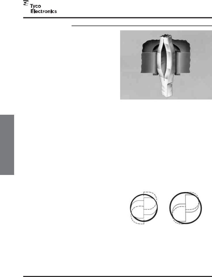
Principle of the Compliant ACTION PIN Post
When a compliant ACTION PIN post is inserted into a plated-through hole, two spring members are compressed, exerting force against the hole for a gas-tight connection. The diameter of the hole is smaller than the diagonal size of the pin (see cross-section illustration below).
The beam characteristics of the pin are designed so that a plastic, as well as an elastic, deformation takes place during insertion. The two spring members compress to different degrees to accommodate hole tolerances. The compliant pin also reduces strain on the board. With a rigid pin, the elastic strain energy is stored entirely in the board, leading to damage of the plated-through holes. With the compliant ACTION PIN post, the residual force of the elastic deformation maintains stored energy to produce a tight contact zone between the pin and the plated-through hole. This maintains long-term electrical and mechanical reliability of the interconnection.
Minimum |
Maximum |
Hole Dia. |
Hole Dia. |
.037 [0.94] |
.043 [1.09] |
Cross-Section Area of ACTION PIN Press-Fit Post in Printed Circuit Board Holes
150
Catalog 1307819 |
Dimensions are in inches and |
Dimensions are shown for |
USA: 1-800-522-6752 |
South America: 55-11-2103-6000 |
Revised 8-08 |
millimeters unless otherwise |
reference purposes only. |
Canada: 1-905-470-4425 |
Hong Kong: 852-2735-1628 |
|
specified. Values in brackets |
Specifications subject |
Mexico: 01-800-733-8926 |
Japan: 81-44-844-8013 |
www.tycoelectronics.com |
are metric equivalents. |
to change. |
C. America: 52-55-1106-0803 |
UK: 44-8706-080-208 |
AMPMODU Interconnection System
ACTION PIN Press-Fit Posts (Continued)
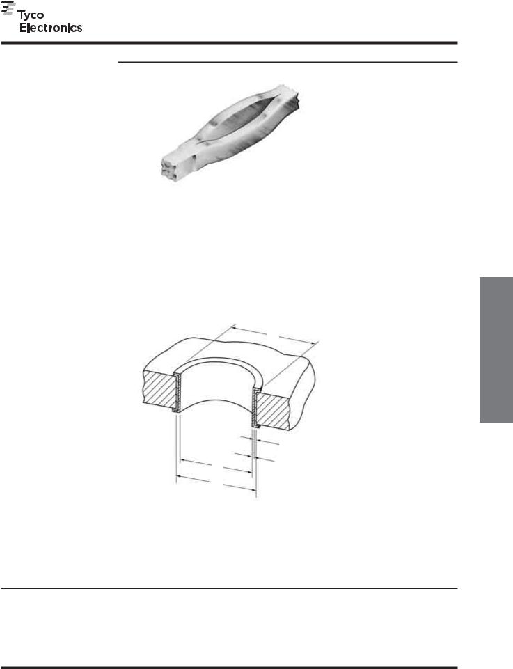
ACTION PIN posts provide a more reliable press-fit connection. Localized pressure in the interface area provides oxide break-through and prevents corrosion better in many of the harshest environments to help provide a reliable connection. Also, radial and axial distortion are controlled to meet today’s standards for multilayer board applications.
PC Board Thickness
ACTION PIN posts are designed for use in a variety of PC board thicknesses. However, certain ACTION PIN posts are to be used in specific ranges of board thicknesses. To promote optimum
performance, the recommended board thicknesses provided with the connector being used must be followed.
Annular Ring (See Note)
Drilled Hole
Copper Thickness
Tin-lead Thickness
Plated-Through Hole
ACTION PIN Post/PC Board Applications
ACTION PIN Contact |
Drilled Hole |
|
Plating Thicknesses |
Plated-Through |
Distortion Specification* |
||||
Material Thickness |
Diameter |
|
Copper * |
Tin-lead |
|
Hole Diameter |
Average |
Maximum |
|
.025 [0.64] |
.0453±.001 [1.151±0.03] |
.001-.003 [0.03-0.08] |
.0003 [0.008]Min. |
.037-.043 [0.94-1.09] |
.0015 [0.038] |
.002 [0.05] |
|
||
*Maximum hardness of copper layer is 150 Knoop. **Radial hole distortion.
Note: Recommended annular ring diameter is hole diameter plus .020 [0.51].
Fit-Press |
ACTION |
Posts |
PIN |
5
Catalog 1307819 |
Dimensions are in inches and |
Revised 8-08 |
millimeters unless otherwise |
|
specified. Values in brackets |
www.tycoelectronics.com |
are metric equivalents. |
151
Dimensions are shown for |
USA: 1-800-522-6752 |
South America: 55-11-2103-6000 |
reference purposes only. |
Canada: 1-905-470-4425 |
Hong Kong: 852-2735-1628 |
Specifications subject |
Mexico: 01-800-733-8926 |
Japan: 81-44-844-8013 |
to change. |
C. America: 52-55-1106-0803 |
UK: 44-8706-080-208 |
ACTION PIN Posts
Application Tooling for
5
AMPMODU Interconnection System
Application Tooling for AMPMODU Headers with ACTION PIN Posts
ACTION PIN Post
Replacement Tooling
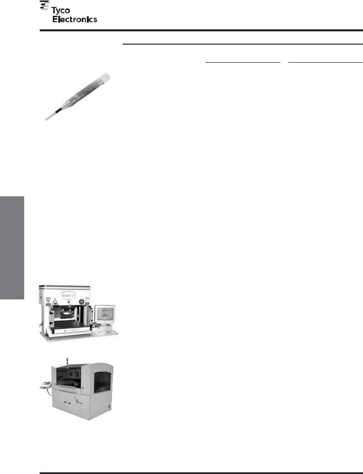
Rear Insertion/Extraction Tool
No. 265871-7 (Ref. 408-2636)
Includes:
Impact Tool No. 380392-8
Removal Tool No. 265964-1
Replacement Tip No. 308554-1
BMEP 5T
AEP 6T
Single-Row Connector
Seating Tools
Tooling Assembly No. 91171-1 is used to install single-row AMPMODU headers with ACTION PIN posts into
PC boards.
Pin headers with ACTION PIN posts allow high speed, solderless back-plane construction through press-fit applica-
tion. Press fitting connectors to printed circuit boards requires special seating tools which transfer application force directly to the contacts.
Force applied to the tool to seat the connectors can be provided by the Tyco Electronics seating machines shown on this page.
For tooling information, call the Tyco Electronics Automation Group 1-800-722-1111.
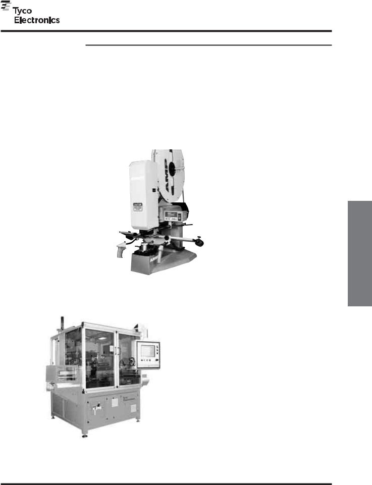
ASG Servo Electric Presses
Tyco Electronics offers a wide range of servo-electric presses for the application of press-fit connectors. Systems are available with varying force capacity, board size capacity and process capability. Each system features real-time force feedback and PC control to allow the highest level of control and traceability. Every connector pressed is
Double-Row Connector
Seating Tools
Header Size |
Tool |
(No. of Pos.) |
Assembly No. |
4 |
91170-1 |
|
|
6 |
91170-1 |
|
|
8 |
91170-2 |
|
|
12 |
91170-5 |
|
|
14 |
91170-6 |
|
|
16 |
91170-7 |
|
|
20 |
91170-9 |
|
|
24 |
1-91170-1 |
|
|
30 |
1-91170-4 |
|
|
36 |
1-91170-7 |
|
|
40 |
1-91170-9 |
|
|
50 |
2-91170-4 |
|
|
60 |
2-91170-9 |
|
|
80 |
3-91170-2 |
|
|
96 |
3-91170-5 |
|
|
100 |
3-91170-6 |
|
|
120 |
3-91170-8 |
|
|
140 |
4-91170-0 |
|
|
200 |
4-91170-2 |
|
|
Triple-Row Connector
Seating Tools
Header Size |
Tool |
(No. of Pos.) |
Assembly No. |
96 |
91169-8 |
|
|
105 |
91169-6 |
|
|
120 |
91169-7 |
|
|
150 |
91169-3 |
|
|
195 |
91169-2 |
|
|
204 |
91169-1 |
|
|
210 |
91169-5 |
|
|
300 |
91169-9 |
|
|
monitored to confirm that maximum force is not exceeded and minimum force is met. Each system controls force, height and speed to allow termination of the pressing cycle by force or height parameters. Complete SPC data is available as each connector press cycle is monitored and stored.
Please see the matrix below and contact
Tyco Electronics Automation Group at 1-800-722-1111 for assistance in understanding which system will best meet your needs.
Press Model |
Description |
Max Pressing Force |
Max Board Size (L x W) |
|
tons [kN] |
in [mm] |
|||
|
|
|||
BMEP 3T |
Semi-automatic, benchtop |
3 [26.7] |
18 x 24 [460 x 610] |
|
servo-electric press |
||||
|
|
|
||
BMEP 5T |
Semi-automatic, benchtop |
5 [44.5] |
18 x 24 [460 x 610] |
|
servo-electric press |
||||
|
|
|
||
|
|
|
|
|
MEP 6T |
Semi-automatic, stand-alone |
6 [53.4] |
24 x 36 [610 x 914] |
|
servo-electric press |
||||
|
|
|
||
MEP 12T |
Semi-automatic, stand-alone |
12 [106.8] |
30 x 36 [ 762 x 914] |
|
servo-electric press |
||||
|
|
|
||
AEP 12T |
Automatic, inline |
12 [106.8] |
36 x 48 [914 x 1219] |
|
servo-electric press |
||||
|
|
|
||
|
|
|
|
|
AEP 6T |
Automatic, stand alone |
6 [53.4] |
30 x 36 [762 x 914] |
|
servo-electric press |
||||
|
|
|
Note: All part numbers are RoHS compliant.
152
Catalog 1307819 |
Dimensions are in inches and |
Dimensions are shown for |
USA: 1-800-522-6752 |
South America: 55-11-2103-6000 |
Revised 8-08 |
millimeters unless otherwise |
reference purposes only. |
Canada: 1-905-470-4425 |
Hong Kong: 852-2735-1628 |
|
specified. Values in brackets |
Specifications subject |
Mexico: 01-800-733-8926 |
Japan: 81-44-844-8013 |
www.tycoelectronics.com |
are metric equivalents. |
to change. |
C. America: 52-55-1106-0803 |
UK: 44-8706-080-208 |
AMPMODU Interconnection System
Application Tooling for Post Insertion
Tyco Electronics offers a wide range of application tooling solutions ranging from stand alone manual insertion systems through fully automatic inline systems. Please contact your local Tyco Electronics representative or the
Tyco Electronics Tooling Assistance Center at 1-800-722-1111 for help in finding the right solution to meet your particular requirements.
Modular Insertion System Bench
Machine No. 217600-1
This machine uses Tyco Electronics insertion heads to install a variety of printed circuit board products at rates of 2,000 per hour. The printed circuit board is placed in a Board Holding Fixture which is attached to a two-hand controlled mechanism. The operator moves the board over the machine anvil; a switch in the anvil actuates the machine when the printed circuit board is placed on the anvil.
A spotlight illuminates the insertion area.
Consult Tyco Electronics for further information on this machine and the insertion heads.
for Tooling Application
Posts PIN ACTION
5
P300 and P350 Automatic Insertion Machines
The P300 and P350 are automatic insertion machines for the application of reeled compliant pin and thru-hole products. Systems are available as stand alone or fully inline with SMEMA compatible conveyor system. Up to 3 different insertion heads can be mounted on a system
allowing one machine to apply up to 3 different products. Insertion rates of up to 3 insertions per second on the P300 and up to 5 insertions per second on a P350 are possible (application dependent). PCBs up to 15.5" x 23.5" [400x600mm] on the P300 and up to 17.5" x 17.5" [450x450mm] on the P350 can be processed by high speed XY positioning tables. A wide range of options, including force monitoring, PCB vision correct, and
PCB thickness measurement are available to meet your performance and production flexibility requirements.
Note: All part numbers are RoHS compliant.
Catalog 1307819 |
Dimensions are in inches and |
Revised 8-08 |
millimeters unless otherwise |
|
specified. Values in brackets |
www.tycoelectronics.com |
are metric equivalents. |
153
Dimensions are shown for |
USA: 1-800-522-6752 |
South America: 55-11-2103-6000 |
reference purposes only. |
Canada: 1-905-470-4425 |
Hong Kong: 852-2735-1628 |
Specifications subject |
Mexico: 01-800-733-8926 |
Japan: 81-44-844-8013 |
to change. |
C. America: 52-55-1106-0803 |
UK: 44-8706-080-208 |
ACTION PIN Stacking |
Connector System |
5
|
|
|
METRIC |
|
|
AMPMODU Interconnection System |
Dimensions are |
|
|
millimeters over inches |
|
|
|
|
|
|
|
|
|
ACTION PIN Stacking Connector System (Non-Intermateable with AMPMODU Connectors)
Product Facts
■Can stack multiple printed circuit boards without the need of a mother board
■Connect bus lines in the shortest possible distance
■Receptacle assembly has ACTION PIN posts for solderless board mounting
■Can be mounted onto the board simply by press fitting with Mini-Press
■Receptacle assembly is easy to service and replace (up to 2 times)
■Receptacle contacts are of fork design to mate with posts at two points.
Virtually eliminates danger of scooping at mating/ unmating
■Stacking dimensions are
13.4[.528] or 19.0 [.748] when using receptacle assemblies together, and
13.9[.547] or 19.5 [.768] when using a combination of receptacle and post header assemblies
■Accepts 1.6 [.062] thick boards
■Housing provided with polarization to help prevent mismating
■Housing made of chemicalresistant glass-filled PBT, black in color
■Contacts are of copper alloy material with high spring characteristics, gold-over- nickel plated
■Post hood available to protect the post portion of receptacle contacts. Can be selected depending on stacking dimensions
■Connectors available in sizes of 26, 30, 34, 40, 50 and 60 positions
■Product specification: 108-5197
ACTION PIN Stacking Connectors are a family of two-piece connectors used to stack multiple printed circuit boards in parallel. They have been developed to provide a more reliable and economical means of compact wiring and highdensity packaging inside a variety of electronic equipment.
The connectors have many advanced features: they can be used to connect
bus lines in the shortest possible distance without the need of a mother board, thus permitting effective utilization of space above the board; compared with other methods of jumper connection using cable connectors, they make the overall board layout more clean and straight for compact packaging.
Contacts are on 2.54 x 2.54 [.100 x .100] grid. The connectors are available in
sizes of 26, 30, 34, 40, 50 and 60 positions. ACTION PIN Stacking Connectors consist of a receptacle assembly, a mating post header and a post hood to protect the post portion of the receptacle assembly.
A complete description of the ACTION PIN Stacking Connectors is
presented on the following page (155).
154
Catalog 1307819 |
Dimensions are in inches and |
Dimensions are shown for |
USA: 1-800-522-6752 |
South America: 55-11-2103-6000 |
Revised 8-08 |
millimeters unless otherwise |
reference purposes only. |
Canada: 1-905-470-4425 |
Hong Kong: 852-2735-1628 |
|
specified. Values in brackets |
Specifications subject |
Mexico: 01-800-733-8926 |
Japan: 81-44-844-8013 |
www.tycoelectronics.com |
are metric equivalents. |
to change. |
C. America: 52-55-1106-0803 |
UK: 44-8706-080-208 |